


 Loading...
OWNER’S SERVICE MANUAL
MANUEL D’ATELIER DU PROPRIETAIRE
FAHRER-UND WARTUNGS-HANDBUCH
MANUALE DI SEVIZIO DEL PROPRIETARIO
YZ125(S)/LC
5XE-28199-30

EC010010
YZ125(S)/LC
OWNER’S SERVICE MANUAL ©2003 by Yamaha Motor Co., Ltd. 1st Edition, May 2003
All rights reserved. Any reprinting or unauthorized use without the written permission of Yamaha Motor Co., Ltd. is expressly prohibited.
Printed in Japan
YZ125(S)/LC
MANUEL D’ATELIER
DU PROPRIETAIRE
©2003 Yamaha Motor Co.,Ltd. 1ère Edition, Mai 2003 Tous droits réservés.
Toute reimpression ou utillisation sans la permission écrite de
la Yamaha Motor Co.,Ltd. est formellement interdite.
Imprimé au Japon
YZ125(S)/LC
FAHRER-UND
WARTUNGSHANDBUCH ©2003 der Yamaha Motor Co., Ltd.
1. Ausgabe, Mai 2003 Alle Rechte vorbehalten.
Nachdruck, auch auszungsweise, oder nicht autorisierte Verwendung ist ohne schriftliche Genehmigung der Yamaha Motor Co., Ltd. nicht gestattet. Gedruckt in Japan
IC010010
YZ125(S)/LC
MANUALE DI SERVIZIO DEL
PROPRIETARIO
© 2003 by Yamaha Motor Co., Ltd. 1a Edizione, Mei 2003
Tutti i diritti riservati. Sono espressamente proibiti qualsiasi ristampa o uso non autorizzato senza il permesso scritto della Yamaha Motor Co., Ltd. Stampato in Giappone

EC020000
INTRODUCTION
Congratulations on your purchase of a Yamaha YZ series. This model is the culmination of Yamaha’s vast experience in the production of pacesetting racing machines. It represents the highest grade of craftsmanship and reliability that have made Yamaha a leader.
This manual explains operation, inspection, basic maintenance and tuning of your machine. If you have any questions about this manual or your machine, please contact your Yamaha dealer.
NOTE:
As improvements are made on this model, some data in this manual may become outdated. If you have any questions, please consult your Yamaha dealer.
w
PLEASE READ THIS MANUAL CAREFULLY AND COMPLETELY BEFORE OPERATING THIS MACHINE. DO NOT ATTEMPT TO OPERATE THIS MACHINE UNTIL YOU HAVE ATTAINED A SATISFACTORY KNOWLEDGE OF ITS CONTROLS AND OPERATING FEATURES AND UNTIL YOU HAVE BEEN TRAINED IN SAFE AND PROPER RIDING TECHNIQUES. REGULAR INSPECTIONS AND CAREFUL MAINTENANCE, ALONG WITH GOOD RIDING SKILLS, WILL ENSURE THAT YOU SAFELY ENJOY THE CAPABILITIES AND THE RELIABILITY OF THIS MACHINE.

INTRODUCTION |
|
IC020000 |
EINLEITUNG |
INTRODUZIONE |
Félicitations pour votre achat d’une Yamaha séries YZ. Ce modèle est l’aboutissement de la vaste expérience de Yamaha dans la production de machines de course. Il représente l’échelon le plus élevé de la dextérité manuelle et de la fiabilité qui ont fait de Yamaha un leader.
Ce manuel explique le fonctionnement, l’inspection, l’entretien de base et la mise au point de votre machine. Si vous avez des questions à poser à propos de ce manuel ou de votre machine, prière de prendre contact avec votre concessionnaire Yamaha.
N.B.:
Comme des améliorations sont faites sur ce modèle, quelques données contenues dans ce manuel peuvent être périmées. Si vous avez des questions à poser, prière de consulter votre concessionnaire Yamaha.
XG
PRIERE DE LIRE ATTENTIVEMENT ET COMPLETEMENT CE MANUEL AVANT D’UTILISER CETTE MACHINE. NE PAS ESSAYER D’UTILISER CETTE MACHINE AVANT DE POSSEDER DES CONNAISSANCES SATISFAISANTES SUR SES COMMANDES ET FONCTIONS ET D’AVOIR ETE FORME POUR DES TECHNIQUES DE CONDUITE CORRECTES ET SURES. DES INSPECTION REGULIERES ET UN ENTRETIEN SOIGNEUX, AVEC UNE BONNE APTITUDE DE CONDUITE, VOUS ASSURERONT LA POSSIBILITE D’APPRECIER LES POSSIBILITES ET LA FIABILITE DE CETTE MACHINE.
Wir möchten Ihnen zum Kauf einer Yamaha YZ Serie, herzlich gratulieren. Dieses Modell entspricht fortschrittlichster Technologie, die auf die jahrelange Erfahrung von Yamaha bei der Produktion von Rennmaschinen zurückzuführen ist. Und die sprichwörtliche Yamaha Zuverlässigkeit wird u.a. durch ausgezeichnete Verarbeitung gewährleistet.
In dieser Anleitung sind der Betrieb, die Prüfung, die grundlegenden Wartungsvorgänge und die Tuning Ihrer neuen Maschine beschrieben. Falls Fragen irgendwelcher Art hinsichtlich dieser Anleitung oder Ihrer Maschine auftauchen sollten, wenden Sie sich bitte an Ihren Yamaha Fachhändler.
HINWEIS:
Aufgrund ständiger Verbesserungen kann es vorkommen, daß manche in dieser Anleitung aufgeführten Daten etwas von der ausgelieferten Maschine abweichen. Falls Fragen auftauchen sollten, wenden Sie sich bitte an Ihren Yamaha Fachhändler.
W
BITTE LESEN SIE DIESE ANLEITUNG AUFMERKSAM UND VOLLSTÄNDIG DURCH, BEVOR SIE DIE MASCHINE IN BETRIEB NEHMEN. VERSUCHEN SIE NIEMALS DIESE MASCHINE ZU FAHREN, BEVOR SIE NICHT ÜBER AUSREICHENDES WISSEN BEZÜGLICH DER STEUER- UND BEDIENUNGSELEMENTE VERFÜGEN UND IN SICHERER UND RICHTIGER FAHRTECHNIK GESCHULT WURDEN. REGELMÄSSIGE INSPEKTIONEN UND SORGFÄLTIGE WARTUNG STELLEN IN VERBINDUNG MIT GUTEN FAHRVERMÖGEN SICHER DASS SIE DIE FÄHIGKEITEN UND DIE ZUVERLÄSSIGKEIT DIESER MASCHINE SICHER NUTZEN KÖNNEN.
Complimenti per avere acquistato una Yamaha serie YZ. Questo modello è il culmine della vasta esperienza della Yamaha nella produzione di veicoli da corsa all’avanguardia. Rappresenta il grado più alto della mano d’opera e dell’affidabilità che hanno fatto della Yamaha un leader.
Il presente manuale spiega il funzionamento, l’ispezione, la manutenzione di base e la messa a punto del veicolo. Se vi sono domande sul presente manuale o sul veicolo, si prega di contattare il concessionario Yamaha.
NOTA:
A mano a mano che a questo modello vengono apportate migliorie, alcuni dati del presente manuale possono diventare obsoleti. Se vi sono domande, si prega di consultare il concessionario Yamaha.
T
SI PREGA DI LEGGERE ATTENTAMENTE E CENTE IL PRESENTE MANUALE PRIMA DI FAR FUNZIONARE IL VEICOLO. NON CERCARE DI FAR FUNZIONARE QUESTO VEICOLO PRIMA DI AVERE RAGGIUNTO UNA CONOSCENZA SODDISFACENTE DEI SUOI COMANDI E DELLE SUE CARATTERISTICHE DI FUNZIONAMENTO E PRIMA DI ESSERE STATI ADDESTRATI ALLE TECNICHE DI GUIDA SICURE E CORRETTE. ISPEZIONI REGOLARI E UN’ATTENTA MANUTENZIONE, INSIEME A BUONE CAPACITÀ DI GUIDA, ASSICURERANNO DI POTERE GODERE DELLE POTENZIALITÀ E DELL’AFFIDABILITÀ DI QUESTO VEICOLO IN MANIERA SICURA.
EC040001
IMPORTANT NOTICE
THIS MACHINE IS DESIGNED STRICTLY FOR COMPETITION USE, ONLY ON A CLOSED COURSE. It is illegal for this machine to be operated on any public street, road, or highway. Off-road use on public lands may also be illegal. Please check local regulations before riding.
 qSAFETY INFORMATION
1.THIS MACHINE IS TO BE OPERATED BY AN EXPERIENCED RIDER ONLY. Do not attempt to operate this machine at maximum power until you are totally familiar with its characteristics.
2.THIS MACHINE IS DESIGNED TO BE RIDDEN BY THE OPERATOR ONLY.
Do not carry passengers on this machine.
3.ALWAYS WEAR PROTECTIVE APPAREL.
When operating this machine, always wear an approved helmet with goggles or a face shield. Also wear heavy boots, gloves, and protective clothing. Always wear proper fitting clothing that will not be caught in any of the moving parts or controls of the machine.
4.ALWAYS MAINTAIN YOUR MACHINE IN PROPER WORKING ORDER.
For safety and reliability, the machine must be properly maintained. Always perform the pre-operation checks indicated in this manual. Correcting a mechanical problem before you ride may prevent an accident.

NOTICE IMPORTANTE
CETTE MACHINE EST STRICTEMENT DESTINEE A LA COMPETITION, UNIQUEMENT SUR CIRCUIT FERME. Il est illégal d’utiliser cette machine sur une rue, route ou artère publique. L’utilisation tous-terrains sur les domaines publics peut également être illégale. Prière de vérifier les lois locales avant de conduire.
qINFORMATION DE SECURITE
1.CETTE MACHINE NE DOIT ETRE UTILISEE QUE PAR UN CONDUCTEUR EXPERIMENTE.
Ne pas essayer d’utiliser cette machine à sa puissance maximum tant que vous n’êtes pas familier avec ses caractéristiques.
2.CETTE MACHINE N’EST CONCUE POUR ETRE UTILISEE QUE PAR LE CONDUCTEUR.
Ne pas prendre de passagers sur cette machine.
3.TOUJOURS PORTER UN EQUIPEMENT DE PROTECTION.
Lors de l’utilisation de cette machine, toujours porter un casque homologué avec des lunettes ou un protège-visage. Porter également de grosses bottes, des gants et des vêtements de protection. Toujours porter des vêtements de taille correcte qui ne seront pas pris dans une des pièces ou commandes mobiles de la machine.
4.TOUJOURS GARDER VOTRE MACHINE EN BON ETAT DE MARCHE.
La machine doit être correctement entretenue pour des questions de sécurité et de fiabilité.
Toujours effectuer les opérations précédant l’utilisation indiquées dans ce manuel.
La correction d’un problème mécanique avant la conduite peut empêcher un éventuel accident.
WICHTIGE HINWEISE
DIESE MASCHINE IST NUR FÜR RENNEN AUF GESCHLOSSENEN KURSEN KONSTRUIERT. ES VERSTÖßT GEGEN DIE VERKEHRSORDNUNG, WENN SIE DIESE MASCHINE AUF ÖFFENTLICHEN STRAßEN ODER AUTOBAHNEN FAHREN. Auch das Fahren im Gelände kann gegen die Verkehrsordnung verstoßen, wenn es sich um öffentliches Eigentum handelt. Bevor Sie diese Maschine fahren, Sollten Sie sich daher mit der örtlichen Verkehrsordnung vertraut machen.
qSICHERHEITSINFORMATION
1.DIESE MASCHINE DARF NUR VON ERFAHRENEN FAHRERN GEFAHREN WERDEN.
Fahren Sie die Maschine niemals mit voller Leistung, bevor Sie sich nicht mit allen Eigenschaften vollständig vertraut gemacht haben.
2.DIESE MASCHINE IST NUR FÜR SOLOFAHRT BESTIMMT.
Niemals elnen Sozius auf dieser Maschine mitführen.
3.IMMER GEEIGNETE SCHUTZKLEIDUGN TRAGEN.
Wenn Sie diese Maschine fahren, immer einen zugelassenen Sturzhelm mit Schutzbrillen oder Schutzschirm tragen. Auch richtige Stiefel Handschuhe und geeignete Schutzkleidung tragen. Darauf achten, daß die kleidung eng anliegt und keine beweglichen Teile oder Bedienungselemente der Maschine berührt.
4.DIE MASCHINE IMMER IN GUTEMBETRIEBSZUSTAND HALTEN.
Die Maschine muß richtig gewartet werden, um hohe Zuverlässigkeit und Fahrsicherheit zu gewäbrleisten.
Immer die in dieser Anleitung aufgeführten Kontrollen vor der Inbetriebnahme durchführen. Die Korrektur mechanischer Probleme vor dem Fahren, kann Unfälle verhindern helfen.
IC040001
NOTA IMPORTANTE
QUESTO VEICOLO È PROGETTATO PER ESSERE USATO RIGOROSAMENTE IN GARA, SOLTANTO SU UN CIRCUITO CHIUSO. È illegale far funzionare questo veicolo su vie, strade o autostrade pubbliche. Anche l’uso fuoristrada su terreni pubblici può essere illegale. Controllare le normative locali prima di usarlo.
qINFORMAZIONI RELATIVE
ALLA SICUREZZA
1.QUESTO VEICOLO DEVE ESSERE FATTO FUNZIONARE SOLTANTO DA UN MOTOCICLISTA ESPERTO. Non tentare di far funzionare questo veicolo alla massima potenza finché non si ha assoluta dimestichezza con le sue caratteristiche.
2.QUESTO VEICOLO È PROGETTATO PER ESSERE USATO SOLTANTO DAL GUIDATORE.
Non trasportare passeggeri su questo veicolo.
3.INDOSSARE SEMPRE EQUIPAGGIAMENTO DI PROTEZIONE.
Quando si usa questo veicolo, indossare sempre un casco omologato con occhiali di protezione o una visiera protettrice. Indossare anche stivali pesanti, guanti e indumenti di protezione. Indossare sempre indumenti che aderiscano correttamente e non rimangano impigliati in una delle parti mobili o dei comandi del veicolo.
4.MANTENERE SEMPRE IL VEICOLO IN PERFETTO ORDINE DI FUNZIONAMENTO.
Per la sicurezza e l’affidabilità, il veicolo deve essere sottoposto a una corretta manutenzione. Eseguire sempre i controlli prima del funzionamento indicati nel presente manuale. Correggere un problema meccanico prima di usare il veicolo può prevenire un incidente.
5.GASOLINE IS HIGHLY FLAMMABLE. Always turn off the engine while refueling. Take care to not spill any gasoline on the engine or exhaust system. Never refuel in the vicinity of an open flame, or while smoking.
6.GASOLINE CAN CAUSE INJURY.
If you should swallow some gasoline, inhale excess gasoline vapors, or allow any gasoline to get into your eyes, contact a doctor immediately. If any gasoline spills onto your skin or clothing, immediately wash skin areas with soap and water, and change your clothes.
7.ONLY OPERATE THE MACHINE IN AN AREA WITH ADEQUATE VENTILATION. Never start the engine or let it run for any length of time in an enclosed area. Exhaust fumes are poisonous. These fumes contain carbon monoxide, which by itself is odorless and colorless. Carbon monoxide is a dangerous gas which can cause unconsciousness or can be lethal.
8.PARK THE MACHINE CAREFULLY; TURN OFF THE ENGINE.
Always turn off the engine if you are going to leave the machine. Do not park the machine on a slope or soft ground as it may fall over.
9.PROPERLY SECURE THE MACHINE BEFORE TRANSPORTING IT.
When transporting the machine in another vehicle, always be sure it is properly secured and in an upright position and that the fuel cock is in the “OFF” position. Otherwise, fuel may leak out of the carburetor or fuel tank.

5.L’ESSENCE EST HAUTEMENT INFLAMMABLE. Toujours arrêter le moteur en faisant le plein. Faire attention à ne pas verser d’essence sur le moteur ou le pot d’échappement. Ne jamais faire le plein au voisinage d’une flamme une ou en fumant.
6.L’ESSENCE PEUT CAUSER DES BLESSURES.
Si vous avalez de l’essence, respirez des vapeurs d’essence en excès ou laissez de l’essence pénétrer dans vos yeux, prendre immédiatement contact avec un médecin. Si de l’essence est renversée sur votre peau ou vos vêtements, laver immédiatement la peau avec du savon et de l’eau et changer de vêtements.
7.N’UTILISER LA MACHINE QUE DANS UN ENDROIT AVEC AERATION ADEQUATE.
Ne jamais mettre le moteur en marche ni le laisser tourner pendant un quelconque laps de temps dans un endroit clos. Les fumées d’échappement sont toxiques. Ces fumées contiennent du monoxyde de carbone incolore et inodore. Le monoxyde de carbone est un gaz toxique dangereux qui peut entraîner la perte de connaissance ou être mortel.
8.STATIONNER AVEC SOIN LA MACHINE ET ARRETER LE MOTEUR.
Toujours arrêter le moteur si vous devez abandonner la machine. Ne pas stationner en pente ou sur un sol mou o.u elle pourrait se renverser.
9.FIXER SOLIDEMENT LA MACHINE AVANT DE LA TRANSPORTER.
En cas de transport de la machine sur un autre véhicule, toujours s’assurer qu’elle est correctement fixée et posée sur ses roues et que le robinet de carburant est dans la position OFF (fermé). Sans quoi il peut y avoir des fuites du carburateur et du réservoir.
5.BENZIN IST BRENNBAR. Immer den Motor abstellen, bevor aufgetankt wird. Darauf achten, daß kein Benzin auf den Motor oder die Auspuffanlage verschüttet wird. Während des Auftankens niemals offene Flammen und Funken in der Nähe der Maschine dulden.
6.BENZIN IST GIFTIG.
Falls versehentlich etwas Benzin getrunken, Benzindämpfe eingeatmet oder Benzin in die Augen gespritzt wurde, sofort einen Arzt aufsuchen. Bei auf die Haut oder Kleidung verschüttetem Benzin, die betroffene Stelle unverzüglich mit Seife und Wasser abwaschen nd ggf. die Kleidung wechseln.
7.DEN MOTOR NUR BEI GUTER BELÜFTUNG LAUFEN LASSEN.
Niemals den Motor in geschlossenen Räumen starten oder für längere Zeit laufen lassen. Die Abgase sind äußerst giftig, da sie Kohlenmonoxid (ein farbund geruchloses Gas) enthalten. Kohlenmonoxid ist es extrem gefährliches Gas, das in kürzester Zeit zu Bewußtlosigkeit und sogor zum Tod führen kann.
8.DIE MASCHINE VORSICHTIG PARKEN UND DEN MOTOR ABSTELLEN.
Immer den Motor abstellen, wenn Sie die Maschine verlassen. Die Maschine niemals auf abschüssigem oder weichen Boden parken, da sonst die Maschine umfallen kann.
9.DIE MASCHINE FÜR DEN TRANSPORT IMMER RICHTIG SICHERN.
Wenn die Maschine in einem anderen Fahrzeug transportiert wird, die Maschine immer in aufrechter Position sichern und den Kraftstoffhahn schließen (Position “OFF”). Anderenfalls kann Kraftstoff aus dem Vergaser oder Kraftstofftank austreten.
5.LA BENZINA È ALTAMENTE INFIAMMABILE. Spegnere sempre il motore durante il rifornimento di carburante. Fare attenzione a non versare benzina sul motore o sul sistema di scarico. Non fare mai rifornimento di carburante in prossimità di una fiamma aperta o mentre si fuma.
6.LA BENZINA PUÒ PROVOCARE LESIONI.
Se si dovesse ingerire un po’ di benzina, inalare vapori di benzina in eccesso o se la benzina dovesse entrare negli occhi, contattare immediatamente un medico. Se si versa benzina sulla pelle o sugli indumenti, lavare immediatamente le zone della pelle con acqua e sapone e cambiarsi i vestiti.
7.FAR FUNZIONARE IL VEICOLO SOLTANTO IN UNA ZONA CON VENTILAZIONE ADEGUATA.
Non avviare mai il motore né farlo funzionare per un certo periodo di tempo in una zona chiusa. I fumi di scarico sono velenosi. Tali fumi contengono monossido di carbonio, che in sé è inodore e incolore. Il monossido di carbonio è un gas pericoloso che può provocare perdita di coscienza o può essere letale.
8.PARCHEGGIARE IL VEICOLO CON ATTENZIONE; SPEGNERE IL MOTORE.
Spegnere sempre il motore se ci si allontana dal veicolo. Non parcheggiare il veicolo in pendenza o su terreno soffice, poiché potrebbe ribaltarsi.
9.FISSARE ADEGUATAMENTE IL VEICOLO PRIMA DI TRASPORTARLO.
Quando si trasporta il veicolo in un altro mezzo di trasporto, assicurarsi sempre che sia fissato adeguatamente e in posizione verticale e che il rubinetto del carburante sia in posizione “OFF”. Altrimenti, il carburante può fuoriuscire dal carburatore o dal serbatoio del carburante.

EC050000
TO THE NEW OWNER
This manual will provide you with a good basic understanding of features, operation, and basic maintenance and inspection items of this machine. Please read this manual carefully and completely before operating your new machine. If you have any questions regarding the operation or maintenance of your machine, please consult your Yamaha dealer.
NOTE:
This manual should be considered a permanent part of this machine and should remain with it even if the machine is subsequently sold.
EC060000
NOTICE
Some data in this manual may become outdated due to improvements made to this model in the future. If there is any question you have regarding this manual or your machine, please consult your Yamaha dealer.
EC070001
F.I.M. MACHINE WEIGHTS:
Weights of machines without fuel
The minimum weights for motocross machines are:
for the class 125 cc |
........................minimum |
|
88 kg (194 lb) |
for the class 250 cc........................ |
minimum |
|
98 kg (216 lb) |
for the class 500 cc........................ |
minimum |
|
102 kg (225 lb) |
In modifying your machine (e.g., for weight reduction), take note of the above limits of weight.
AU NOUVEAU
PROPRIETAIRE
Ce manuel vous apportera une connaissance de base des caractéristiques, du fonctionnement, et des entretiens de base et des détais d’inspection de cette machine.
Veuillez lire soigneusement et entièrement ce manuel avant d’utiliser votre nouvelle machine. Si vous avez des questions concernant le fonctionnement ou l’entretien de votre machine, veuillez consulter votre concessionnaire Yamaha.
N.B.:
Ce manuel doit être considéré comme partie permanente de la machine et doit rester avec celle-ci si elle est revendue à une tierce personne.
AVERTISSEMENT
Certaines données contenues dans ce manuel risquent de devenir périmées du fait d’améliorations apportées à ce modèle dans le futur. Pour toute question concernant ce manuel ou votre machine, veuillez consulter votre concessionnaire Yamaha.
POIDS DES MACHINES,
SPECIFICATION F.I.M.:
Poids des machines sans carburant
Les poids minimum admis pour les machines de motocross sont:
pour la catégorie 125 cc
................................minimum 88 kg (194 lb)
pour la catégorie 250 cc
................................minimum 98 kg (216 lb)
pour la catégorie 500 cc
................................minimum 102 kg (225 lb)
Lorsque vous modifiez votre machine (par exemple pour réduction de poids), tenir compte des limites de poids spécifiées ci-dessus.
AN DEN FAHRER
Dieses Handbuch beschreibt die wichtigsten Merkmale und Bedienungsvorgänge sowie die grundlegenden War- tungs-und Prüfpunkte dieser Maschine.
Bitte lesen Sie dieses Handbuch aufmerksam und vollständig durch, bevor Sie Ihre neue Maschine in Betrieb nehmen.
Falls Fragen hinsichtlich der Bedienung oder Wartung auftauchen sollten, wenden Sie sich bitte an Ihren Yamaha Fachhändler.
HINWEIS:
Diese Anleitung sollte als Bestandteil der Maschine angesehen werden und auch beim Verkauf der Maschine dem neuen Besitzer übergeben werden.
ANMERKUNG
Die in diesem Handbuch aufgeführten Daten und Abbildungen entsprechen dem neuesten Stand zum Zeitpunkt der Drucklegung. Es kann daher vorkommen, daß gewisse Einzelheiten der ausgelieferten Maschine aufgrund ständiger Verbesserung von diesem Handbuch abweichen. Falls Fragen hinsichtlich dieses Handbuches oder Ihrer Maschine auftauchen sollten, wenden Sie sich bitte an Ihren Yamaha Fachhändler.
GEWICHT DER
F.I.M.-MASCHINE:
Gewicht der Maschine ohne Kraftstoff
Das Mindestgewicht für eine MotocrossMaschine ist: für 125 cc Klasse
.................................Mindest 88 kg (194 lb)
für 250 cc Klasse
.................................Mindest 98 kg (216 lb)
für 500 cc Klasse
.................................Mindest 102 kg (225 lb)
Falls Sie Modifikationen an Ihrer Maschine vornehmen (z.B. zur Gewichtsverringerung), unbedingt das oben angeführte Mindestgewicht Ihre Klasse einhalten.
IC050000
PER IL NUOVO
PROPRIETARIO
Questo manuale fornirà una buona comprensione di base delle caratteristiche, del funzionamento e delle operazioni fondamentali di manutenzione e di ispezione di questo veicolo. Si prega di leggere attentamente e completamente questo manuale prima di far funzionare il veicolo nuovo. Se vi sono domande riguardanti il funzionamento o la manutenzione del veicolo, consultare il concessionario Yamaha.
NOTA:
Il presente manuale dovrebbe essere considerato parte integrante di questo veicolo e dovrebbe rimanere insieme a esso anche se il veicolo viene poi venduto.
IC060000
NOTA BENE
Alcuni dati del presente manuale possono diventare obsoleti per via di migliorie apportate a questo modello in futuro. Se vi sono domande riguardo al presente manuale o al veicolo, consultare il concessionario Yamaha.
IC070001
PESI DEI VEICOLI
SECONDO LA F.I.M.:
Pesi dei veicoli senza carburante
I pesi minimi per i veicoli per motocross sono:
per la classe 125 cc |
..............minimo |
|
88 kg (194 lb) |
per la classe 250 cc.............. |
minimo |
|
98 kg (216 lb) |
per la classe 500 cc.............. |
minimo |
|
102 kg (225 lb) |
Se si modifica il veicolo (per esempio per ridurne il peso), tenere conto dei limiti di peso sopra-riportati.

EC080000
HOW TO USE
THIS MANUAL
EC081000
PARTICULARLY IMPORTANT IN FORMATION
Q
The Safety Alert Symbol means ATTENTION! BECOME ALERT! YOUR SAFETY IS INVOLVED!
w
Failure to follow WARNING instructions could result in severe injury or death to the machine operator, a bystander, or a person inspecting or repairing the machine.
cC
A CAUTION indicates special precautions that must be taken to avoid damage to the machine.
NOTE:
A NOTE provides key information to make procedures easier or clearer.
EC082000
FINDING THE REQUIRED PAGE
1.This manual consists of seven chapters; “General Information”, “Specifications”, “Regular inspection and adjustments”, “Engine”, “Chassis”, “Electrical” and “Tuning”.
2.The table of contents is at the beginning of the manual. Look over the general layout of the book before finding then required chapter and item.
Bend the book at its edge, as shown, to find the required fore edge symbol mark and go to a page for required item and description.

COMMENT
UTILISER CE
MANUEL
INFORMATIONS PARTICULIEREMENT
IMPORTANTES
Q
Le symbole d’alerte de sécurité signifie ATTENTION! SOYEZ VIGILANT! VOTRE SECURITE EST EN JEU!
XG
Le non-respect des instructions AVERTISSEMENT peut entraîner de sérieuses blessures ou la mort au pilote de la machine, à un passant ou à une personne inspectant ou réparant la machine.
fF
Une ATTENTION indique les procédures spéciales qui doivent être suivies pour éviter d’endommager la machine.
N.B.:
Une N.B. fournit les renseignements nécessaires pour rendre les procédures plus faciles ou plus claires.
TROUVER LA PAGE
RECHERCHEE
1.Ce manuel comprend 7 chapitres: “Renseignements généraux”, “Caractéristiques”, “Verification et réglages courants”, “Moteur”, “Partie cycle”, “Partie électrique” et “Mise au point”.
2.La table des matières se trouve au d’ebut du manuel.
Regarder la disposition générale du manuel avant de recherche le chapitre et l’article désirés.
Arquer le manuel à son bord, de la manière indiquée, pour trouver le symbole de devant désiré et passer à une page de la description et l’article désirés.
VERWENDUNG
DIESER ANLEITUNG
WICHTIGE INFORMATION
Q
Das Sicherheitssymbol bedeutet „AUFPASSEN“!
VORSICHT IST GEBOTEN ZU IHRER EIGENEN SICHERHEIT.
W
Nichtbeachtung der Warnhinweise kann zu Verletzungen oder Lebensgefahr für den Fahrer, Wartungsmechaniker oder anderer, dritter Personen führen.
dD
Unter „ACHTUNG“ sind besondere Vorsichtsmaßnahmen aufgeführt, die Eingehalten werden müssen, um Beschädigungen der Maschine zu verhindern.
HINWEIS:
Ein HINWEIS gibt Zusatzinformationen und Tips, um bestimmte Vorgänge oder Arbeiten zu vereinfachen.
AUFFINDEN EINER
GEWÜNSCHTEN SEITE
1.Diese Anleitung besteht aus sieben Kapiteln: „Allgemeine Angaben“, „Technische Daten“, „Regelmäßige Prüfungen und Einstellungen“, „Motor“, „Fahrgestell“, „Elektrishe Einrichtungen“ und „Tuning“.
2.Das Inhaltverzeichnis befindet sich am Beginn der Anleitung. Machen Sie sich mit der allgemeinen Auslegung des Buches vertraut, bevor Sie ein bestimmtes Kapitel und einen bestimmten Artikel auffinden.
Das Buch an der Kante abbiegen, wie in der Abbildung gezeigt, um die vier Symbolmarkierungen aufzufinden und danach die Seite aufsuchen für den erforderlichen Artikel und die Beschreibung.
IC080000
COME USARE IL
PRESENTE
MANUALE
IC 081000
INFORMAZIONI PARTICOLARMENTE
IMPORTANTI
Q
Il Simbolo di Allerta in materia di Sicurezza significa ATTENZIONE! STARE ALL’ERTA! RIGUARDA LA SICUREZZA!
T
L’inosservanza delle istruzioni delle AVVERTENZE potrebbe comportare lesioni gravi o morte per il guidatore del veicolo, per uno spettatore o per una persona che ispezioni o ripari il veicolo.
iI
Un paragrafo che inizi con ATTENZIONE indica precauzioni particolari che si devono prendere per evitare danni al veicolo.
NOTA:
Una NOTA fornisce informazioni-chia- ve per rendere più semplici o più chiare le procedure.
IC082000
COME TROVARE LA PAGINA RICHIESTA
1.Il presente manuale comprende sette capitoli: “Informazioni Generali”, “Specifiche”, “Ispezione e regolazioni regolari”, “Motore”, “Telaio”, “Parte elettrica" e “Messa a punto”.
2.L’indice si trova all’inizio del manuale. Esaminare l’impostazione generale del libro prima di trovare il capitolo e la voce richiesti.
Piegare il libro sul bordo, come illustrato, per trovare il simbolo sul bordo anteriore richiesto e andare a una pagina per la voce e la descrizione richieste.
EC083000
MANUAL FORMAT
All of the procedures in this manual are organized in a sequential, step-by-step format. The information has been complied to provide the mechanic with an easy to read, handy reference that contains comprehensive explanations of all disassembly, repair, assembly, and inspection operations.
In this revised format, the condition of a faulty component will precede an arrow symbol and the course of action required will follow the symbol, e.g.,
9Bearings Pitting/Damage→ Replace.
EC084002
HOW TO READ DESCRIPTIONS
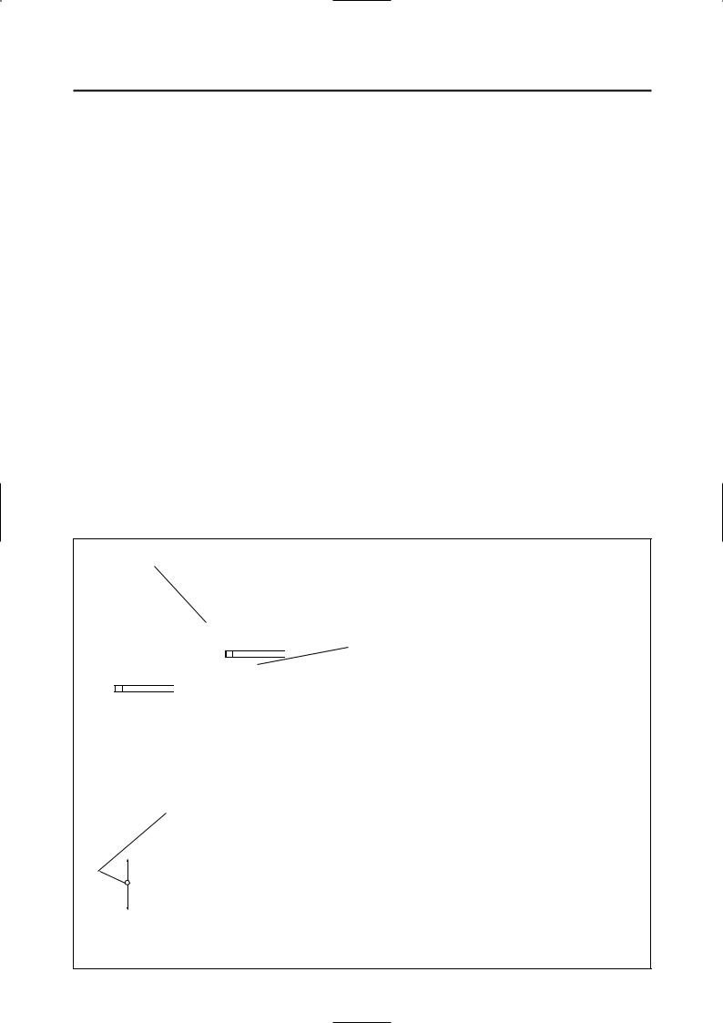
To help identify parts and clarify procedure steps, there are exploded diagrams at the start of each removal and disassembly section.
1.An easy-to-see exploded diagram 1 is provided for removal and disassembly jobs.
2.Numbers 2 are given in the order of the jobs in the exploded diagram. A number that is enclosed by a circle indicates a disassembly step.
3.An explanation of jobs and notes is presented in an easy-to-read way by the use of symbol marks 3. The meanings of the symbol marks are given on the next page.
4.A job instruction chart 4 accompanies the exploded diagram, providing the order of jobs, names of parts, notes in jobs, etc.
5.Extent of removal 5 is provided in the job instruction chart to save the trouble of an unnecessary removal job.
6.For jobs requiring more information, the step-by-step format supplements 6 are given in addition to the exploded diagram and job instruction chart.
1
4
5
|
CLUTCH AND PRIMARY DRIVEN GEAR |
|
ENG |
|
|
|
|
|
CLUTCH AND PRIMARY DRIVEN GEAR |
|
ENG |
|
|
|
|
|||||||||||
|
|
|
|
|
|
|
|
|
|
|
|
|
|
|
|
|
|
|
|
|
|
|
|
|
|
|
EC490000 |
|
|
|
|
|
|
|
|
|
|
|
|
|
|
EC493000 |
|
|
|
|
|||||||
|
|
|
|
|
|
|
|
|
|
|
|
å |
|
|
|
|
|
|||||||||
|
|
|
|
|
|
|
|
|
|
|
|
|
|
|
|
|
|
|
||||||||
CLUTCH AND PRIMARY DRIVEN GEAR |
|
|
|
|
|
|
|
|
|
|
REMOVAL POINTS |
|
|
|
|
|
||||||||||
EC498000 |
|
|
|
|
|
|
|
|
|
|
|
|
|
|
EC483211 |
|
|
|
|
|||||||
CLUTCH PLATE AND FRICTION PLATE |
|
|
|
|
|
|
|
|
|
|
Clutch boss |
|
|
|
|
|
||||||||||
|
|
|
|
|
|
|
|
|
|
|
|
|
||||||||||||||
|
|
|
|
|
|
|
|
|
|
|
|
|
|
|
|
1. Remove: |
|
|
|
|
|
|||||
|
|
|
|
|
|
|
|
|
|
|
|
|
|
|
|
9Nut 1 |
|
|
|
|
|
|||||
|
|
|
|
|
|
|
|
|
|
|
|
|
|
|
|
9Lock washer 2 |
|
|
|
|
|
|||||
|
|
|
|
|
|
|
|
|
|
|
2 |
|
|
|
9Clutch boss 3 |
|
|
|
|
|
||||||
|
|
|
|
|
|
|
|
|
|
|
|
|
NOTE: |
|
|
|
|
|
|
|
|
|
||||
|
|
|
|
|
10 Nm (1.0 m•kg, 7.2 ft•lb) |
|
|
|
|
|
|
|
|
Straighten the lock washer tab and use the |
|
6 |
||||||||||
|
|
|
|
|
|
|
|
|
|
|
|
|
||||||||||||||
|
|
|
|
|
|
|
|
|
|
|
|
|
|
|
clutch holding tool 4, 5 to hold the clutch boss. |
|
|
|||||||||
|
|
|
|
|
|
|
|
|
|
|
|
|
∫ |
|
|
|
|
|
|
|
|
|
|
|
|
|
|
|
|
|
|
|
|
|
|
|
|
|
|
|
|
|
|
|
|
|
|
|
|
|
|
|
|
|
|
|
|
|
|
|
|
|
|
|
|
|
|
|
|
|
|
|
|
|
|
|
|
|
|
|
|
|
|
|
|
|
|
|
|
|
|
|
|
|
|
|
|
|
|
|
|
|
|
|
|
|
|
|
|
|
|
|
|
|
|
|
|
|
|
|
|
|
|
|
|
Clutch holding tool: |
|
|
|
|||||
|
|
|
|
|
|
|
|
|
|
|
|
|
|
|
|
|
|
|
|
|
||||||
|
|
|
|
|
|
|
|
|
|
|
|
|
|
YM-91042................................ 4 |
|
|
|
|||||||||
10 Nm (1.0 m•kg, 7.2 ft•lb) |
|
|
|
|
|
|
|
|
|
|
|
|
|
90890-04086............................5 |
|
|
||||||||||
|
|
|
|
|
|
|
|
|
|
|
|
|
|
|
|
|
|
|
||||||||
|
|
|
|
|
|
|
|
|
|
|
|
|
|
|
å For USA and CDN |
|
|
|
|
|
||||||
|
|
|
|
|
|
|
|
|
|
|
|
|
|
|
∫ Except for USA and CDN |
|
|
|
|
|
||||||
|
|
|
|
|
|
|
|
|
|
|
|
|
|
|
EC494000 |
|
|
|
|
|
||||||
|
|
|
|
|
|
|
|
|
|
|
|
|
|
|
|
|
|
|
|
|||||||
|
|
|
|
|
|
|
|
|
|
|
3 |
|
|
INSPECTION |
|
|
|
|
|
|||||||
|
|
|
|
|
|
|
|
|
|
|
|
|
EC484100 |
|
|
|
|
|
||||||||
|
|
|
|
|
|
|
|
|
|
|
|
|
|
|
|
|
|
|
|
|||||||
|
|
|
|
|
|
|
|
|
|
|
|
|
|
|
Clutch housing and boss |
|
|
|
|
|
||||||
|
|
|
|
|
|
|
|
|
|
|
|
|
|
|
|
1. Inspect: |
|
|
|
|
|
|||||
|
|
|
|
|
|
|
|
|
|
|
|
|
|
|
|
9Clutch housing 1 |
|
|
|
|
|
|||||
|
|
|
|
|
|
|
|
|
|
|
|
|
|
|
|
Cracks/Wear/Damage → Replace. |
|
|
||||||||
|
|
|
|
|
|
|
|
|
|
|
|
|
|
|
|
9Clutch boss 2 |
|
|
|
|
|
|||||
|
|
|
|
|
|
|
|
|
|
|
|
|
|
|
|
Scoring/Wear/Damage → Replace. |
|
|
||||||||
|
|
|
|
|
|
|
|
|
|
|
|
|
|
|
EC484201 |
|
|
|
|
|
||||||
|
|
|
|
|
|
|
|
|
|
|
|
|
|
|
|
|
|
|
|
|||||||
|
|
|
|
|
|
|
|
|
|
|
|
|
|
|
Primary driven gear |
|
|
|
|
|
||||||
|
|
|
|
|
|
|
|
|
|
|
|
|
|
|
|
1. Check: |
|
|
|
|
|
|||||
Extent of removal: |
|
1 Clutch plate and friction plate removal |
|
|
|
|
|
|
|
|
|
|
|
|
||||||||||||
|
|
|
|
|
|
|
|
|
|
9Circumferential play |
|
|
|
|
|
|||||||||||
|
|
|
|
|
|
|
|
|
|
|
|
|
|
|
|
|
|
|
|
|
||||||
Extent of removal |
Order |
|
|
Part name |
Q’ty |
|
|
Remarks |
|
|
|
|
|
Free play exists → Replace. |
|
|
||||||||||
|
|
|
CLUTCH PLATE AND |
|
|
|
|
|
|
|
|
|
|
|
9Gear teeth a |
|
|
|
|
|
||||||
|
|
|
FRICTION PLATE REMOVAL |
|
|
|
|
|
|
|
|
|
|
|
Wear/ Damage → Replace. |
|
|
|||||||||
Preparation for |
|
|
Drain the transmission oil. |
|
Refer to “TRANSMISSION OIL REPLACE- |
|
|
|
|
|
|
|
||||||||||||||
|
|
|
|
|
|
|
|
|
|
|
|
|
|
|
|
|
|
|
||||||||
removal |
|
|
|
|
|
MENT“ section in the CHAPTER 3. |
|
|
|
|
|
|
|
|
|
|
|
|
|
|
|
|
||||
|
|
|
Bolt (brake pedal) |
|
Shift the brake pedal downward. |
|
|
|
|
|
|
|
|
|
|
|
|
|
|
|
|
|||||
|
|
|
Clutch cable |
|
Disconnect at engine side. |
|
|
|
|
EC484400 |
|
|
|
|
|
|||||||||||
|
|
|
|
|
|
|
|
|
|
|
|
|
|
|
|
|
|
|
|
|||||||
|
1 |
|
Clutch cover |
1 |
|
|
|
|
|
|
|
|
|
Clutch spring |
|
|
|
|
|
|||||||
|
2 |
|
Screw (clutch spring) |
5 |
|
|
|
|
|
|
|
|
|
|
1. Measure: |
|
|
|
|
|
||||||
|
3 |
|
Clutch spring |
5 |
|
|
|
|
|
|
|
|
|
|
|
|
|
|
|
|||||||
|
|
|
|
|
|
|
|
|
|
|
|
9Clutch spring free length a |
|
|
||||||||||||
1 |
4 |
|
Pressure plate |
1 |
|
|
|
|
|
|
|
|
|
|
|
|
||||||||||
5 |
|
Push rod |
1 |
|
|
|
|
|
|
|
|
|
|
Out of specification → Replace springs as |
|
|
||||||||||
|
6 |
|
Plain washer |
2 |
|
|
|
|
|
|
|
|
|
|
a set. |
|
|
|
|
|
||||||
|
7 |
|
Bearing |
1 |
|
|
|
|
|
|
|
|
|
|
|
|
|
|
|
|
|
|
|
|
|
|
|
8 |
|
Friction plate |
8 |
|
|
|
|
|
|
|
|
|
|
|
|
Clutch spring free length: |
|
|
|
||||||
|
9 |
|
Clutch plate |
7 |
|
|
|
|
|
|
|
|
|
|
|
|
|
|
|
|||||||
|
|
|
|
|
|
|
|
|
|
|
|
|
|
|
|
|
|
|
|
|
|
|
||||
|
|
|
|
|
|
|
|
|
|
|
|
|
|
|
|
|
|
|
|
|
|
|
|
|
|
|
|
|
|
|
|
|
|
|
|
|
|
|
|
|
|
|
|
Standard |
|
<Limit> |
|
|
|
||||
|
|
|
|
|
|
|
|
|
|
|
|
|
|
|
|
|
40.1 mm |
|
38.1 mm |
|
|
|
||||
|
|
4-30 |
|
|
|
|
|
|
|
|
|
4-32 |
|
(1.579 in) |
|
(1.500 in) |
|
|
|
|||||||
|
|
|
|
|
|
|
|
|
|
|
|
|
|
|
|
|
|
|
|
|
|
|||||

FORMAT DU MANUEL
Dans ce manuel, toutes les procédures sont décrites pas à pas. Les informations ont été condensées pour fournir au mécanicien un guide pratique et facile à lire, contenant des explications claires pour toutes les procédures de démontage, réparation, remontage et vérification.
Dans ce nouveau format, l’état d’un composant défectueux est suivi d’une flèche qui indique les mesures à prendre. Exemple:
9Roulements Piqûres/endommagement →Remplacer.
FORMAT DER ANLEITUNG
Allen dieser Anleitung enthaltenen Vorgänge sind sequentiell in der durchzuführenden Reihenfolge aufgeführt. Diese Anleitung wurde zusammengestellt, um den Mechanikern ein leicht verständliches Nachschlagwerk in die Hand zu geben, das Beschreigungen für Demontage, Reparatur, Montage und Inspektion enthält.
Im Format dieser Anleitung wird nach dem Bauteil die Störungsursache gefolgt von einer Pfeilmarkierung aufgeführt, an die sich dann die erforderlich Maßnahme anschließt, wie es im folgenden Beispiel dargestellt ist.
9Lager Grübchenbildung/
Beschädigung→Erneuern.
COMMENT LIRE LES DESCRIPTIONS
Chaque section détaillant des étapes de démontage ou de remontage est précédée de vues en éclaté qui permettent de clarifier ces opérations.
1.Exemple de vue en éclaté 1 clarifiant les opérations de démontage et de remontage.
2.Sur les vues en éclaté, les pièces sont numérotées 2 dans l’ordre des opérations à effectuer. Un chiffre entouré d’un cercle correspond à une étape de démontage.
3.Les vues en éclaté portent également des symboles 3 qui rappellent des points importants à ne pas oublier. La signification de ces symboles est expliquée à la page suivante.
4.Les vues en éclaté sont suivies d’un tableau 4 fournissant l’ordre des opérations, le nom des pièces, des remarques, etc.
5.Pour éviter la dépose superflue de pièces, l’étendue de la dépose 5 est indiquée dans le tableau de description du travail.
6.Pour les travaux qui demandent des explications supplémentaires, la vue en éclaté et le tableau sont suivis d’une description détaillée 6 des opérations.
LESEN DER BESCHREIBUNGEN
Um bei der Identifikation der Teile zu helfen und die Arbeitsschritte zu verdeutlichen, sind Explosionsdiagramme am Beginn jedes Ausbauund Demontageabschnittes dargestellt.
1.Für die Ausbauund Demontagearbeiten ist meistens ein übersichtliches Explosionsdiagramm 1 dargestellt.
2.Die Nummern 2 in dem Explosionsdiagramm sind in der Reihenfolge der Arbeiten aufgeführt. Eine in einen Kreis eingeschriebene Nummer bezeichnet einen Demontageschritt.
3.Eine Erläuterung der Arbeiten und Hinweise ist durch ablesefreundliche Symbolmarkierungen 3 gegeben. Die Bedeutungen der Symbolmarkierungen sind auf der nächsten Seite aufgeführt.
4.Eine Arbeitsanweisungstabelle 4 begleitet das Explosionsdiagramm und gibt die Arbeitsreihenfolge, Bezeichnung der Teile, Hinweise zu den Arbeiten usw. an.
5.Der Umfang des Ausbaus 5 ist in der Arbeitsanweisungstabelle aufgeführt, um nicht erforderliche Ausbauarbeiten zu vermeiden.
6.Für Arbeiten, für die weitere Informationen benötigt werden, sind schrittweise Ergänzungen 6 zusätzlich zu dem Explosionsdiagramm und der Arbeitsanweisungstabelle aufgeführt.
IC083000
FORMATO DEL MANUALE
Tutte le procedure contenute nel presente manuale sono organizzate in formato sequenziale, passo dopo passo. Le informazioni sono state compilate in modo da fornire al meccanico un riferimento facile da leggere e maneggevole che contenga spiegazioni esaustive di tutte le operazioni di smontaggio, riparazione, montaggio e ispezione.
In questo formato rivisto, la condizione di un componente difettoso precederà il simbolo di una freccia e l’azione richiesta seguirà il simbolo, per esempio
9Cuscinetti
Puntinatura/Danni → Sostituirli.
IC084002
COME LEGGERE LE DESCRIZIONI
Per facilitare l’individuazione delle parti e chiarire le fasi procedurali, vi sono diagrammi esplosi all’inizio di ciascuna sezione relativa alla rimozione e allo smontaggio.
1.Per i lavori di rimozione e smontaggio viene fornito un diagramma esploso facile da vedere 1.
2.Nel diagramma esploso vengono forniti numeri 2 nell’ordine dei lavori. Un numero racchiuso da un circoletto indica un’operazione di smontaggio.
3.Una spiegazione dei lavori e delle note viene presentata in maniera facilmente leggibile mediante l’uso di simboli 3. I significati dei simboli vengono riportati nella pagina seguente.
4.Una tabella con le istruzioni di lavoro 4 accompagna il diagramma esploso, fornendo l’ordine dei lavori, i nomi delle parti, le note relative ai lavori, ecc.
5.Per risparmiare il fastidio di un lavoro di rimozione inutile, nella tabella con le istruzioni di lavoro viene fornita l’ampiezza della rimozione 5.
6.Per i lavori che richiedono maggiori informazioni, oltre al diagramma esploso e alla tabella con le istruzioni di lavoro vengono forniti i supplementi in formato passo dopo passo 6.

1 |
|
2 |
GEN |
|
SPEC |
INFO |
|
|
|
|
|
3 |
|
4 |
INSP |
|
ENG |
ADJ |
|
|
|
|
|
5 |
|
6 |
CHAS |
|
ELEC |
7 |
|
8 |
TUN |
|
|
9 |
|
0 |
q |
|
w |
e |
|
r |
t |
y |
u |
i |
|
o |
p |
|
a |
EC085002
ILLUSTRATED SYMBOLS (Refer to the illustration)
Illustrated symbols 1 to 7 are designed as thumb tabs to indicate the chapter’s number and content.
1 General information
2 Specifications
3 Regular inspection and adjustments
4 Engine
5 Chassis
6 Electrical
7 Tuning
Illustrated symbols 8 to r are used to identify the specifications appearing in the text.
8 With engine mounted
9 Special tool
0 Filling fluid q Lubricant w Tightening
e Specified value, Service limit
r Resistance (Ω), Voltage (V), Electric current (A)
Illustrated symbols t to o in the exploded diagrams indicate grade of lubricant and location of lubrication point.
t Apply transmission oil y Apply engine mixing oil
u Apply molybdenum disulfide oil
i Apply lightweight lithium-soap base grease o Apply molybdenum disulfide grease
Illustrated symbols p to a in the exploded diagrams indicate where to apply a locking agent and where to install new parts.
p Apply locking agent (LOCTITER) a Use new one

SYMBOLES GRAPHIQUES (Voir l’illustration)
Les symboles graphiques 1 à 7 servent à repérer les différents chapitres et à indiquer leur contenu.
1 Renseignements généraux
2 Caracteristiques
3 Verification et réglages courants
4 Moteur
5 Partie cycle
6 Partie électrique
7 Mise au point
Les symboles graphiques 8 á r permettent d’identifier les spécifications encadrées dans le texte.
8 Avec de montage du moteur
9 Outil spécial
0 Liquide de remplissage q Lubrifiant
w Serrage
e Valeur spécifiée, limite de service
r Résistance (Ω), tension (V), intensité (A)
Les symboles graphiques t à o dans les vues éclatées indiquent le grade de lubrifiant et l’emplacement des points de lubrification.
t Appliquer de l’huile de transmission
y Appliquer de l’huile de mélange du moteur
u Appliquer de l’huile au bisulfure de molybdène i Appliquer de la graisse fluide à base de savon
au lithium
oAppliquer de la graisse au bisulfure de molybdène
Les symboles graphiques p et a dans les vues éclatées indiquent où appliquer de l’agent bloquant et où installer de nouveaux composants.
pAppliquer un agent de blocage (LOCTITE®)
a Utiliser une pièce neuve
ABGEBILDETEN SYMBOLE (Siehe Abbildung)
Die abgebildeten Symbole 1 bis 7 sind zur einfachen Auffindung der Seiten mit Daumeneinkerbungen versehen. Die Abschnittsnummer sowie der lnhalt können sofort ersehen werden.
1 Allgemein Angaben
2 Technische Daten
3Regelmäßige Prüfung und Einstellungen
4 Motor
5 Fahrgestell
6 Elektrische Einrichtungen
7 Tuning
Die abgebildeten Symbole von 8 bis
rwerden zur Unterscheidung der Spezifikationen in diesem Text benutzt.
8 Mit dem Motor eingebaut
9 Spezialwerkzeug
0 Einfüllen von Flüssigkeit q Schmiermittel
w Festziehen (Anzugsmoment) e Verschleißgrenze, Wartungs-
Toleranzgrenze
rWiderstand (Ω), Spannung (V), elektrischer Strom (A)
Die abgebildeten Symbole t bis o in der Explosionszeichnung zeigen die Schmierstoffklasse sowie die Schmierstellen an.
t Getriebeöl auftragen
y Motor-Mischöl auftragen
u Molybdändisulfid-Öl auftragen i Leichtes Lithium-Fett auftragen o Molybdändisulfid-Fett auftragen
Die abgebildeten Symbole p bis a in der Explosionszeichnung zeigen die Stellen, wo Sicherungslack aufzutragen ist und neue Teile einzubauen sind.
p Sicherungslack (LOCTITE®) auftragen
a Neues Teil verwenden
IC085002
SIMBOLI ILLUSTRATI (Fare riferimento all’illustrazione)
I simboli illustrati da 1 a 7 sono progettati come linguette da sfogliare che indichino il numero e il contenuto del capitolo.
1 Informazioni generali
2 Specifiche
3 Ispezione e regolazioni regolari
4 Motore
5 Telaio
6 Parte elettrica
7 Messa a punto
I simboli illustrati da 8 a r vengono usati per identificare le specifiche che compaiono nel testo.
8 Con motore montato
9 Utensile speciale
0 Liquido di riempimento q Lubrificante
w Serraggio
e Valore specificato, limite di servizio
rResistenza (Ω), Tensione (V), Corrente elettrica (A)
I simboli da t a o illustrati nei diagrammi esplosi indicano la qualità di lubrificante e la posizione del punto di lubrificazione.
t Applicare olio per trasmissione
y Applicare olio per miscela per motori
u Applicare olio a base di bisolfuro di molibdeno
iApplicare grasso leggero a base di sapone di litio
oApplicare grasso a base di bisolfuro di molibdeno
I simboli p e a illustrati nei diagrammi esplosi indicano dove applicare l’agente bloccante e dove montare il pezzo di ricambio.
pApplicare agente bloccante (LOCTITE®)
a Usare un pezzo nuovo

EC090010
INDEX
GENERAL INFORMATION
SPECIFICATIONS
REGULAR INSPECTION AND ADJUSTMENTS
ENGINE
CHASSIS
ELECTRICAL
TUNING
 2004 Owner's manual")
INDEX |
INDEX |
RENSEIGNEMENTS |
ALLGEMEIN |
GENERAUX |
ANGABEN |
CARACTERISTIQUES |
TECHINSCHE |
|
DATEN |
||
|
VERIFICATION ET |
REGELMÄSSIGE |
|
PRÜFUNG |
||
REGLAGES |
||
UND |
||
COURANTS |
||
EINSTELLUNGEN |
||
|
MOTEUR |
MOTOR |
PARTIE CYCLE |
FAHRGESTELL |
PARTIE |
ELEKTRISCHE |
ELECTRIQUE |
EINRICHTUNGEN |
MISE AU POINT |
TUNING |
IC090010
INDICE
ANALITICO
INFORMAZIONI
GENERALI GEN 1
INFO
SPECIFICHE
SPEC 2
ISPEZIONE E
REGOLAZIONI
REGOLARI INSP 3
ADJ
MOTORE
ENG 4
TELAIO
CHAS 5
PARTE ELETTRICA
ELEC 6
MESSA A PUNTO
TUN 7

EC0A0000
CONTENTS
CHAPTER 1
GENERAL INFORMATION
DESCRIPTION............................................ |
1-1 |
MACHINE IDENTIFICATION ...................... |
1-2 |
IMPORTANT INFORMATION ..................... |
1-3 |
CHECKING OF CONNECTION .................. |
1-6 |
SPECIAL TOOLS........................................ |
1-7 |
CONTROL FUNCTIONS............................. |
1-9 |
FUEL AND ENGINE MIXING OIL............. |
1-12 |
STARTING AND BREAK-IN ..................... |
1-13 |
TORQUE-CHECK POINTS....................... |
1-16 |
CLEANING AND STORAGE .................... |
1-17 |
CHAPTER 2
SPECIFICATIONS
GENERAL SPECIFICATIONS .................... |
2-1 |
MAINTENANCE SPECIFICATIONS ........... |
2-3 |
GENERAL TORQUE SPECIFICATIONS..2-12 |
|
DEFINITION OF UNITS ............................ |
2-12 |
CABLE ROUTING DIAGRAM .................. |
2-13 |
CHAPTER 3
REGULAR INSPECTION
AND ADJUSTMENTS
MAINTENANCE INTERVALS..................... |
3-1 |
PRE-OPERATION INSPECTION AND |
|
MAINTENANCE.......................................... |
3-4 |
ENGINE....................................................... |
3-5 |
CHASSIS................................................... |
3-17 |
ELECTRICAL............................................ |
3-38 |
TABLES DES |
|
INHALTSVERZEICHNIS |
|
MATIERES |
|
|
|
CHAPITRE 1 |
|
KAPITEL 1 |
|
RENSEIGNEMENTS |
|
ALLGEMEIN |
|
GENERAUX |
|
ANGABEN |
|
DESCRIPTION ........................................... |
1-1 |
BESCHREIBUNG ....................................... |
1-1 |
IDENTIFICATION DE LA MACHINE ... |
1-2 |
MASCHINEN-IDENTIFIKATION................. |
1-2 |
INFORMATIONS IMPORTANTES ........ |
1-3 |
WICHTIGE INFORMATIONEN ................... |
1-3 |
VÉRIFICATION DES CONNEXIONS .... |
1-6 |
ANSCHLÜSSE PRÜFEN ............................ |
1-6 |
OUTILS SPECIAUX................................... |
1-7 |
SPEZIALWERKZEUGE .............................. |
1-7 |
FONCTIONS DES COMMANDES........... |
1-9 |
BEDIENUNGSELEMENTE ......................... |
1-9 |
ESSENCE ET HUILE DE MELANGE |
|
KRAFTSTOFF UND |
|
DU MOTEUR ............................................ |
1-12 |
MOTORGEMISCHÖL ............................... |
1-12 |
MISE EN MARCHE ET RODAGE ........ |
1-13 |
STARTEN UND EINFAHREN................... |
1-13 |
POINTS DE VERIFICATION DE |
|
ANZUGSMOMENTE-PRÜFPUNKTE ....... |
1-16 |
COUPLE DE SERRAGE.......................... |
1-16 |
REINIGEN UND LAGERUNG |
1-17 |
|
|
||
NETTOYAGE ET RANGEMENT.......... |
1-17 |
|
|
IC0A0000
INDICE
CAPITOLO 1
INFORMAZIONI
GENERALI
DESCRIZIONE ........................................... |
1-1 |
IDENTIFICAZIONE DEL VEICOLO ..... |
1-2 |
INFORMAZIONI IMPORTANTI............. |
1-3 |
CONTROLLO DEI COLLEGAMENTI... |
1-6 |
UTENSILI SPECIALI ................................ |
1-7 |
FUNZIONI DEI COMANDI ...................... |
1-9 |
CARBURANTE E OLIO PER MISCELA |
|
PER MOTORI ........................................... |
1-12 |
AVVIO E RODAGGIO............................. |
1-13 |
PUNTI DI CONTROLLO DELLA |
|
COPPIA ...................................................... |
1-16 |
PULITURA E IMMAGAZZINAMENTO..1-17
CHAPITRE 2 |
|
KAPITEL 2 |
|
CAPITOLO 2 |
|
|
CARACTERISTIQUES |
TECHNISCHE DATEN |
|
SPECIFICHE |
|
||
CARACTERISTIQUES GENERALES |
....2-1 |
ALLGEMEINE TECHNISCHE DATEN ....... |
2-1 |
SPECIFICHE GENERALI ........................ |
2-1 |
|
CARACTERISTIQUES D'ENTRETIEN .2-3 |
WARTUNGSDATEN ................................... |
2-3 |
SPECIFICHE DI MANUTENZIONE....... |
2-3 |
||
SPECIFICATIONS GENERALES |
|
ALLGEMEINE ANZUGSDATEN .............. |
2-12 |
SPECIFICHE GENERALI RELATIVE |
|
|
DE COUPLE .............................................. |
2-12 |
DEFINITION DER EINHEITEN ................. |
2-12 |
ALLA COPPIA.......................................... |
2-12 |
|
DEFINITION DES UNITES .................... |
2-12 |
KABELFÜHRUNGSÜBERSICHTPLAN ... |
2-13 |
DEFINIZIONE DELLE UNITÀ.............. |
2-12 |
|
SCHEMA DE CHEMINEMENT DES |
|
|
|
DIAGRAMMA DEL PASSAGGIO |
|
|
CABLES ..................................................... |
2-13 |
|
|
DEI CAVI................................................... |
2-13 |
|
CHAPITRE 3 |
|
KAPITEL 3 |
|
CAPITOLO 3 |
|
|
VERIFICATION ET |
|
REGELMÄSSIGE PRÜ- |
REVISIONE E |
|
||
REGLAGES COURANTS |
FUNG |
|
REGOLAZIONI |
|
||
|
|
UND EINSTELLUNGEN |
REGOLARI |
|
||
PROGRAMME D’ENTRETIEN ............... |
3-1 |
|
|
INTERVALLI DI MANUTENZIONE ...... |
3-1 |
|
INSPECTION ET ENTRETIEN |
|
WARTUNGSINTERVALLE |
3-1 |
ISPEZIONE E MANUTENZIONE PRIMA |
||
AVANT UTILISATION |
3-4 |
DEL FUNZIONAMENTO |
3-4 |
|||
PRÜFUNG UND WARTUNG VOR |
|
|||||
MOTEUR |
3-5 |
|
MOTORE |
3-5 |
||
DER INBETRIEBNAHME ........................... |
3-4 |
|||||
PARTIE CYCLE ....................................... |
3-17 |
MOTOR ....................................................... |
3-5 |
TELAIO...................................................... |
3-17 |
|
PARTIE ELECTRIQUE .......................... |
3-38 |
FAHRGESTELL ........................................ |
3-17 |
PARTE ELETTRICA ............................... |
3-38 |
|
|
|
ELEKTRISCHE EINRICHTUNGEN .......... |
3-38 |
|
|
|

CHAPTER 4
ENGINE
SEAT, FUEL TANK AND SIDE |
|
COVERS ..................................................... |
4-1 |
EXHAUST PIPE AND SILENCER .............. |
4-3 |
RADIATOR.................................................. |
4-4 |
CARBURETOR AND REED VALVE........... |
4-7 |
CYLINDER HEAD , CYLINDER AND |
|
PISTON ..................................................... |
4-17 |
CLUTCH AND PRIMARY DRIVEN |
|
GEAR ....................................................... |
4-30 |
KICK AXLE, SHIFT SHAFT AND |
|
PRIMARY DRIVE GEAR........................... |
4-38 |
YPVS GOVERNOR................................... |
4-46 |
WATER PUMP .......................................... |
4-49 |
CDI MAGNETO ......................................... |
4-53 |
ENGINE REMOVAL .................................. |
4-57 |
CRANKCASE AND CRANKSHAFT......... |
4-62 |
TRANSMISSION, SHIFT CAM AND |
|
SHIFT FORK............................................. |
4-69 |
CHAPTER 5
CHASSIS
FRONT WHEEL AND REAR WHEEL |
........5-1 |
FRONT BRAKE AND REAR BRAKE....... |
5-10 |
FRONT FORK........................................... |
5-26 |
HANDLEBAR............................................ |
5-39 |
STEERING ................................................ |
5-46 |
SWINGARM .............................................. |
5-51 |
REAR SHOCK ABSORBER..................... |
5-59 |

CHAPITRE 4 |
|
KAPITEL 4 |
|
MOTEUR |
|
MOTOR |
|
SELLE, RESERVOIR A ESSENCE |
|
SITZ, KRAFTSTOFFTANK UND |
|
ET COUVERCLES LATERAUX.............. |
4-1 |
SEITENDECKEL......................................... |
4-1 |
TUYAU D’ECHAPPEMENT ET |
|
AUSPUFFROHR UND |
|
SILENCIEUX .............................................. |
4-3 |
SCHALLDÄMPFER .................................... |
4-3 |
RADIATEUR ............................................... |
4-4 |
KÜHLER...................................................... |
4-4 |
CARBURATEUR ET |
|
VERGASER UND ZUNGENVENTIL........... |
4-7 |
SOUPAPE FLEXIBLE ............................... |
4-7 |
ZYLINDERKOPF, ZYLINDER UND |
|
|
|
|
|
CULASSE, CYLINDRE ET PISTON ..... |
4-17 |
KOLBEN ................................................... |
4-17 |
EMBRAYAGE ET PIGNON |
|
KUPPLUNG UND |
|
MENE PRIMAIRE.................................... |
4-30 |
PRIMÄRABTRIEBSZAHNRAD ................ |
4-30 |
AXE DE DEMARREUR AU PIED, |
|
KICKSTARTERWELLE, SCHALTWELLE |
|
ARBRE DE SELECTEUR ET PIGNON |
|
UND PRIMÄRANTRIEBSZAHNRAD ....... |
4-38 |
DE TRANSMISSION PRIMAIRE .......... |
4-38 |
YPVS REGLER |
4-46 |
|
|
||
REGULATEUR YPVS.............................. |
4-46 |
WASSERPUMPE |
4-49 |
|
|
||
POMPE A EAU ......................................... |
4-49 |
CDI-MAGNETZÜNDER |
4-53 |
|
|
||
MAGNETO CDI........................................ |
4-53 |
AUSBAU DES MOTORS |
4-57 |
|
|
||
DEPOSE DU MOTEUR ........................... |
4-57 |
KURBELGEHÄUSE UND |
|
|
|
|
|
CARTER ET VILEBREQUIN................. |
4-62 |
KURBELWELLE ....................................... |
4-62 |
BOITE A VITESSES, BARILLET |
|
GETRIEBE, SCHALTNOCKE UND |
|
DE SELECTEUR ET FOURCHETTE ... |
4-69 |
SCHALTGABEL ....................................... |
4-69 |
CAPITOLO 4
MOTORE
SELLA, SERBATOIO DEL |
|
CARBURANTE E COPERTURE |
|
LATERALI .................................................. |
4-1 |
TUBO DI SCARICO E |
|
SILENZIATORE......................................... |
4-3 |
RADIATORE............................................... |
4-4 |
CARBURATORE E VALVOLA A |
|
LAMELLA ................................................... |
4-7 |
TESTA CILINDRO, CILINDRO E |
|
PISTONE.................................................... |
4-17 |
FRIZIONE E INGRANAGGIO |
|
CONDOTTO PRIMARIO........................ |
4-30 |
PEDIVELLA, ALBERO DEL |
|
CAMBIO E INGRANAGGIO |
|
CONDUTTORE PRIMARIO................... |
4-38 |
REGOLATORE YPVS ............................. |
4-46 |
POMPA DELL’ACQUA........................... |
4-49 |
MAGNETE CDI ........................................ |
4-53 |
RIMOZIONE DEL MOTORE................. |
4-57 |
CARTER E ALBERO A GOMITI .......... |
4-62 |
TRASMISSIONE, CAMMA DEL |
|
CAMBIO E FORCELLA DEL |
|
CAMBIO .................................................... |
4-69 |
CHAPITRE 5 |
|
KAPITEL 5 |
|
CAPITOLO 5 |
|
|
PARTIE CYCLE |
|
FAHRGESTELL |
|
TELAIO |
|
|
ROUE AVANT ET ROUE ARRIERE ...... |
5-1 |
VORDERRAD UND HINTERRAD .............. |
5-1 |
RUOTA ANTERIORE E RUOTA |
|
|
FREIN AVANT ET FREIN ARRIERE |
5-10 |
VORDERRADBREMSE UND |
|
POSTERIORE ............................................. |
5-1 |
|
|
|
|
||||
FOURCHE AVANT |
5-26 |
HINTERRADBREMSE .............................. |
5-10 |
FRENO ANTERIORE E FRENO |
|
|
|
|
POSTERIORE |
5-10 |
|||
GUIDON |
5-39 |
VORDERRADGABEL |
5-26 |
|||
|
|
|||||
|
|
FORCELLA ANTERIORE |
5-26 |
|||
DIRECTION |
5-46 |
LENKSTANGE |
5-39 |
|||
|
|
|||||
|
|
MANUBRIO |
5-39 |
|||
BRAS OSCILLANT |
5-51 |
LENKUNG |
5-46 |
|||
|
|
|||||
|
|
STERZO |
5-46 |
|||
AMORTISSEUR ARRIERE |
5-59 |
HINTERRADSCHWINGE |
5-51 |
|||
|
|
|||||
|
|
FORCELLONE OSCILLANTE |
5-51 |
|||
|
|
HINTERRAD-STOSSDÄMPFER |
5-59 |
|||
|
|
|
|
AMMORTIZZATORE POSTERIORE..5-59

CHAPTER 6
ELECTRICAL
ELECTRICAL COMPONENTS AND |
|
WIRING DIAGRAM..................................... |
6-1 |
IGNITION SYSTEM..................................... |
6-2 |
|
CHAPTER 7 |
|
TUNING |
ENGINE....................................................... |
7-1 |
CHASSIS................................................... |
7-14 |

CHAPITRE 6 |
|
KAPITEL 6 |
|
PARTIE |
|
ELEKTRISCHE |
|
ELECTRIQUE |
|
EINRICHTUNGEN |
|
COMPOSANTS ELECTRIQUES |
|
ELEKTRISCHE BAUTEILE UND |
|
ET SCHEMA DE CABLAGE .................... |
6-1 |
SCHALTPLAN ............................................ |
6-1 |
SYSTEME D’ALLUMAGE ....................... |
6-2 |
ZÜNDANLAGE ........................................... |
6-2 |
CAPITOLO 6
PARTE ELETTRICA
COMPONENTI ELETTRICI E SCHEMA
ELETTRICO ............................................... |
6-1 |
SISTEMA DI ACCENSIONE .................... |
6-2 |
CHAPITRE 7 |
|
KAPITEL 7 |
|
CAPITOLO 7 |
|
MISE AU POINT |
|
TUNING |
|
MESSA A PUNTO |
|
MOTEUR ..................................................... |
7-1 |
MOTOR ....................................................... |
7-1 |
MOTORE ..................................................... |
7-1 |
PARTIE CYCLE ....................................... |
7-14 |
FAHRGESTELL ........................................ |
7-14 |
TELAIO...................................................... |
7-14 |

GEN
DESCRIPTION INFO
EC100000
GENERAL INFORMATION
EC110000
DESCRIPTION
1 Clutch lever
2 “ENGINE STOP” button
3 Front brake lever
4 Throttle grip
5 Radiator cap
6 Fuel tank cap
7 Kick starter
8 Fuel tank
9 Radiator
0 Coolant drain bolt
q Check bolt (Transmission oil level) w Rear brake pedal
e Valve joint r Fuel cock t Air cleaner y Drive chain u Shift pedal i Starter knob o Front fork
NOTE:
9The machine you have purchased may differ slightly from those shown in the following.
9Designs and specifications are subject to change without notice.
1-1

DESCRIPTION
BESCHREIBUNG
DESCRIZIONE
IC100000
GEN INFO
RENSEIGNEMENTS |
ALLGEMEIN |
INFORMAZIONI |
GENERAUX |
ANGABEN |
GENERALI |
|
|
IC110000 |
DESCRIPTION
1 Levier d’embrayage
2Bouton de coupe-circuit de sécurité “ENGINE STOP”
3 Levier de frein avant
4 Poignée d’accélérateur
5 Bouchon du radiateur
6 Bouchon de réservoir à essence
7 Kickstarter
8 Réservoir de carburant
9 Radiateur
0Boulon de vidange du liquide de refroidissement
q Boulon de contrôle
(niveau d’huile de transmission) w Pédale de frein arrière
e Joint de robinet r Robinet à essence t Filtre à air
y Chaîne de transmission u Pédale de sélecteur
i Bouton de starter o Fourche avant
N.B.:
9La machine que vous avez achetée diffère peutêtre partiellement de celles montrées sur ces photos.
9La conception et les caractéristiques peuvent êtres changées sans préavis.
BESCHREIBUNG
1 Kupplungshebel
2 Motorstoppknopf „ENGINE STOP“
3 Handbremshebel
4 Gasdrehgriff
5 Kühlerdeckel
6 Kraftstofftank-Verschluß
7 Kickstarter
8 Kraftstofftank
9 Kühler
0 Kühlmittel-Ablaßschraube
q Prüfschraube (Getriebeölstand)
w Fußbremshebel
e Ventilverbindung
r Kraftstoffhahn
t Luftfilter
y Antriebskette
u Schalthebel
i Starterknopf
o Vorderradgabel
HINWEIS:
9Die von Ihnen gekaufte Maschine könnte etwas von den hier gezeigten Abbildungen abweichen.
9Anderungen des Designs und der Technischen Daten ohne vorhergehende Bekanntgage vorbehalten.
DESCRIZIONE
1 Leva di comando della frizione
2 Pulsante “ARRESTO MOTORE”
3 Leva di comando del freno anteriore
4 Manopola dell’acceleratore 1
5 Tappo del radiatore
6 Tappo del serbatoio del carburante
7 Pedivella della messa in moto
8 Serbatoio del carburante
9 Radiatore
0Bullone di drenaggio del liquido refrigerante
qBullone di controllo
(livello dell’olio della trasmissione)
w Pedale di comando del freno posteriore e Giunto della valvola
r Rubinetto del carburante t Filtro dell’aria
y Catena di trasmissione u Pedale del cambio
i Manopola dell’avviamento o Forcella anteriore
NOTA:
9Il veicolo acquistato può essere leggermente diverso da quelli illustrati qui sotto.
9Progetti e specifiche sono soggetti a variazioni senza preavviso.
1-1

MACHINE IDENTIFICATION
EC120001
GEN INFO
MACHINE IDENTIFICATION
There are two significant reasons for knowing the serial number of your machine:
1.When ordering parts, you can give the number to your Yamaha dealer for positive identification of the model you own.
2.If your machine is stolen, the authorities will need the number to search for and identify your machine.
EC121001
VEHICLE IDENTIFICATION NUMBER (For USA, CDN, AUS, NZ and E)
The vehicle identification number 1 is stamped on the right of the steering head pipe.
EC122001
FRAME SERIAL NUMBER (For F, D, GB, I and ZA)
The frame serial number 1 is stamped on the right of the steering head pipe.
EC123001
ENGINE SERIAL NUMBER
The engine serial number 1 is stamped into the elevated part of the right-side of the engine.
EC124000
MODEL LABEL
The model label 1 is affixed to the frame under the rider’s seat. This information will be needed to order spare parts.
1-2

IDENTIFICATION DE LA MACHINE
MASCHINEN-IDENTIFIKATION
IDENTIFICAZIONE DEL VEICOLO
IC120001
GEN INFO
IDENTIFICATION DE LA MACHINE
Il existe deux bonnes raisons de connaître les numéros de série de votre machine:
1.A la commande de pièces de rechange, vous pourrez donner ces numéros au concessionnaire Yamaha qui pourra identifier clairement le modèle correspondant à la machine que vous possédez.
2.Si votre machine est volée, la police aura besoin de ces numéros pour retrouver et identifier votre machine.
MASCHINEN-
IDENTIFIKATION
Bitte immer die Seriennummern Ihrer Maschine beachten; diese werden besonders in den beiden folgenden Fällen benötigt:
1.Bei der Bestellung von Ersatzteilen muß die Seriennummer angegeben werden, damit Ihr Yamaha Fachhändler das Modell richtig identifizieren kann.
2.Wenn Ihr Motorrad gestohlen wird, dann benötigen die Gesetzesvertreter die Seriennummer Ihrer Maschine, um diese wieder auffinden und identifizieren zu können.
IDENTIFICAZIONE DEL VEICOLO
Vi sono due motivi importanti per conoscere il numero di serie del veicolo:
1.Quando si ordinano parti di ricambio, si può dare il numero al concessionario Yamaha per un’identificazione certa del modello posseduto.
2.Se il veicolo viene rubato, le autorità avranno bisogno del numero per ricercare e identificare il veicolo.
IC121001
NUMERO D’IDENTIFICATION DU VEHICULE (Pour USA, CDN, AUS, NZ et E)
Le numéro d’identification du véhicule 1 est frappé du côté droit du tube de tête de fourche.
NUMERO DE SERIE DU CADRE (Pour F, D, GB, I et ZA)
Le numéro de série du cadre 1 est frappé du côté droit du tube de tête de fourche.
NUMERO DE SERIE DU MOTEUR
Le numéro de série du moteur 1 est estampé sur un bossage sur le côté droit du moteur.
ETIQUETTE D’IDENTIFICATION DU MODELE
L’étiquette d’identification du modèle 1 est apposée sur le cadre, sous la selle du pilote. Les informations reprises sur cette étiquette sont requises lors de la commande de nouvelles pièces.
FAHRGESTELLNUMMER
(Für USA, CDN, AUS, NZ and E)
Die Fahrgestell-Seriennummer 1 ist an der rechten Seite in das Lenkkopfrohr eingeschlagen.
RAHMENNUMMER (Für F, D, GB, I und ZA)
Die Seriennummer des Rahmens 1 ist an der rechten Seite in das Lenkkopfrohr eingeschlagen.
SERIENNUMMER DES MOTORS
Die Motor-Serienummer 1 ist an dem erhöhten Teil an der rechten Seite des Motors eingeschlagen.
MODELLCODE-INFORMATION
Das Modellcode-Klebeschild 1 ist an dem Rahmen unter dem Fahrersitz angebracht. Diese Informationen benötigen Sie zur Ersatzteil-Bestel- lung.
NUMERO DI IDENTIFICAZIONE DEL VEICOLO
(Per USA, CDN, AUS, NZ ed E)
Il numero di identificazione del veicolo 1 è stampigliato sulla destra del tubo di testa di sterzo.
IC122001
NUMERO DI SERIE DEL TELAIO (Per F, D, GB, I e ZA)
Il numero di serie del telaio 1 è stampigliato sulla destra del tubo di testa di sterzo.
IC123001
NUMERO DI SERIE DEL MOTORE
Il numero di serie del motore 1 è stampigliato sulla parte rialzata del lato destro del motore.
IC124000
ETICHETTA DEL MODELLO
L’etichetta del modello 1 è affissa al telaio sotto la sella del guidatore. Queste informazioni saranno necessarie per ordinare parti di ricambio.
1-2

GEN 


IMPORTANT INFORMATION INFO
EC130000
IMPORTANT INFORMATION
EC131010
PREPARATION FOR REMOVAL AND
DISASSEMBLY
1.Remove all dirt, mud, dust, and foreign material before removal and disassembly. When washing the machine with high pressured water, cover the parts as follows. 9Silencer exhaust port
9Side cover air intake port
9Crankcase cover hole at the bottom
9Water pump housing hole at the bottom
2.Use proper tools and cleaning equipment. Refer to “SPECIAL TOOLS” section.
3.When disassembling the machine, keep mated parts together. They include gears, cylinders, pistons, and other mated parts that have been “mated” through normal wear. Mated parts must be reused as an assembly or replaced.
4.During the machine disassembly, clean all parts and place them in trays in the order of disassembly. This will speed up assembly time and help assure that all parts are correctly reinstalled.
5.Keep away from fire.
1-3
Loading...