


Z200
Table of contents
 Loading...
Z200
LZ200
OWNER’S MANUAL
68F-28199-19
U.S.A.Edition
LIT-18626-07-00
EMU25071
ZMU01690
Read this owner’s manual carefully before operating your outboard motor.
Important manual information
EMU31280
To the owner
Thank you for choosing a Yamaha outboard
motor. This Owner’s Manual contains infor-
mation needed for proper operation, mainte-
nance and care. A thorough understanding
of these simple instructions will help you ob-
tain maximum enjoyment from your new
Yamaha. If you have any question about the
operation or maintenance of your outboard
motor, please consult a Yamaha dealer.
In this Owner’s Manual particularly important
information is distinguished in the following
ways.
The Safety Alert Symbol means
ATTENTION! BECOME ALERT! YOUR
SAFETY IS INVOLVED!
WARNING
EWM00780
Failure to follow WARNING instructions
could result in severe injury or death
to
the machine operator, a bystander, or a
person inspecting or repairing the out-
board motor.
CAUTION:
ECM00700
A CAUTION indicates special precautions
that must be taken to avoid damage to the
outboard motor.
NOTE:
A NOTE provides key information to make
procedures easier or clearer.
Yamaha continually seeks advancements in
product design and quality. Therefore, while
this manual contains the most current prod-
uct information available at the time of print-
ing, there may be minor discrepancies
between your machine and this manual. If
there is any question concerning this manu-
al, please consult your Yamaha dealer.
NOTE:
The Z200TR, LZ200TR and the standard ac-
cessories are used as a base for the expla-
nations and illustrations in this manual.
Therefore some items may not apply to ev-
ery model.
EMU25110
Z200, LZ200
OWNER’S MANUAL
©2006 by Yamaha Motor Corporation, USA
1st edition, April 2006
All rights reserved.
Any reprinting or unauthorized use
without the written permission of
Yamaha Motor Corporation, USA
is expressly prohibited.
Printed in Japan
P/N LIT-18626-07-00

Table of contents
General information .......................... 1
Identification numbers record.......... 1
Outboard motor serial number .......... 1
Key number....................................... 1
Emission control information ........... 1
North American models..................... 1
Star labels ......................................... 2
Safety information ........................... 3
Important labels............................... 4
Warning labels ..................................4
Caution labels ...................................5
Basic boating rules
(Rules of the road) ........................5
Steering and sailing rules and
sound signals.................................. 6
Rules when encountering vessels .... 6
Other special situations..................... 7
Fueling instructions ......................... 9
Gasoline.......................................... 10
Engine oil ........................................10
Battery requirement....................... 10
Battery specifications ...................... 11
Propeller selection......................... 11
Start-in-gear protection ................. 11
Basic components ..........................12
Main components.......................... 12
Remote control................................ 13
Remote control lever....................... 14
Neutral interlock trigger................... 14
Neutral throttle lever........................ 14
Free accelerator.............................. 15
Throttle friction adjuster................... 15
Engine stop lanyard switch .............16
Main switch .....................................16
Power trim and tilt switch on
remote control or tiller handle .......17
Power trim and tilt switch on
bottom engine cowling .................. 17
Power trim and tilt switches
(twin binnacle type)....................... 18
Trim tab with anode ........................ 18
Tilt support lever for power trim
and tilt or hydro tilt model.............. 19
Top cowling lock levers................... 19
Flushing device ............................... 20
Water separator ..............................20
Tachometer .....................................20
Digital tachometer ...........................20
Oil level indicators
(three indicators) ........................... 21
Oil level indicator (digital type) ........21
Overheat warning indicator
(digital type) ..................................21
Speedometer (digital type) ..............22
Trim meter....................................... 22
Trim meter (digital type) ..................23
Hour meter (digital type).................. 23
Trip meter........................................ 23
Clock ...............................................24
Fuel gauge ......................................24
Fuel warning indicator .....................24
Low battery voltage warning
indicator ........................................25
Fuel management meter .................25
Fuel flow meter................................ 25
Fuel consumption meter.................. 26
Fuel economy.................................. 26
Twin-engine speed synchronizer ....27
Command link multifunction
meters ........................................... 27
Tachometer unit ..............................27
Speed & fuel meter unit................... 31
Speedometer unit............................ 32
Fuel management meter .................33
Warning system ............................ 33
Overheat warning (twin engines) ....33
Oil level warning and oil filter
clogging warning ........................... 34
Operation ......................................... 36
Installation..................................... 36
Mounting the outboard motor ..........36
Breaking in engine ........................ 37
Procedure for HPDI models ............38
Preoperation checks ..................... 38
Fuel .................................................38
Oil.................................................... 39
Controls........................................... 39
Engine .............................................39
Operation after a long period of
storage .......................................... 39

Table of contents
Filling fuel and engine oil............... 40
Filling fuel for models without a
fuel joint ........................................ 40
Ring Free Fuel Additive .................. 40
Filling oil for oil injection models...... 40
Oil level indicator operation............. 42
Operating engine........................... 43
Feeding fuel ....................................43
Starting engine................................ 43
Warming up engine ....................... 45
Electric start and prime start
models .......................................... 45
Shifting .......................................... 45
Forward (tiller handle and remote
control models) ............................. 46
Reverse (automatic reverse lock
and power trim and tilt models)..... 46
Stopping engine ............................ 47
Procedure ....................................... 47
Trimming outboard motor.............. 47
Adjusting trim angle ........................ 48
Adjusting boat trim ..........................49
Tilting up and down ....................... 49
Procedure for tilting up
(power trim and tilt models /
power tilt models).......................... 50
Procedure for tilting down
(power trim and tilt models /
power tilt models).......................... 51
Cruising in shallow water .............. 52
Power trim and tilt models /
power tilt models........................... 52
Cruising in other conditions........... 53
Maintenance..................................... 54
Specifications ................................ 54
Transporting and storing outboard
motor ........................................... 55
Storing outboard motor ...................55
Procedure ....................................... 56
Lubrication (oil injection models)..... 57
Cleaning and anticorrosion
measures ...................................... 57
Battery care..................................... 57
Flushing power unit......................... 58
Cleaning the outboard motor .......... 59
Checking painted surface of
motor............................................. 59
Periodic maintenance ................... 59
Replacement parts ..........................59
Maintenance chart........................... 60
Maintenance chart (additional)........ 61
Greasing.......................................... 62
Cleaning and adjusting spark
plug ............................................... 62
Checking fuel system ......................63
Inspecting idling speed.................... 64
Checking water in engine oil tank ...64
Checking wiring and connectors .....64
Exhaust leakage.............................. 65
Water leakage .................................65
Checking power trim and tilt
system........................................... 65
Checking propeller ..........................66
Removing the propeller ...................67
Installing the Propeller..................... 67
Changing gear oil ............................68
Inspecting and replacing
anode(s)........................................ 69
Checking battery (for electric start
models) ......................................... 69
Connecting the Battery.................... 70
Disconnecting the battery................ 71
Checking top cowling ......................71
Coating the boat bottom.................. 72
Trouble Recovery............................ 73
Troubleshooting ............................ 73
Temporary action in emergency ... 76
Impact damage ...............................76
Running single engine..................... 76
Replacing fuse ................................77
Power trim and tilt / power tilt will
not operate.................................... 77
Water separator warning indicator
blinks while cruising ...................... 78
Starter will not operate ....................79
Emergency starting engine .............80
Engine fails to operate .................. 81
Low oil level warning activates........ 81
Treatment of submerged motor .... 82
Procedure........................................ 82

Table of contents
Consumer information.................... 83
Important warranty information for
U.S.A. and Canada ..................... 83
YAMAHA MOTOR
CORPORATION, U.S.A.
OUTBOARD MOTOR TWO
YEAR LIMITED WARRANTY ...... 85
IMPORTANT WARRANTY
INFORMATION IF YOU USE
YOUR YAMAHA OUTSIDE
THE USA OR CANADA .............. 88
1
General information
EMU25170
Identification numbers record
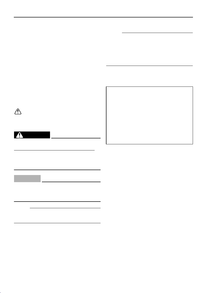
EMU25183
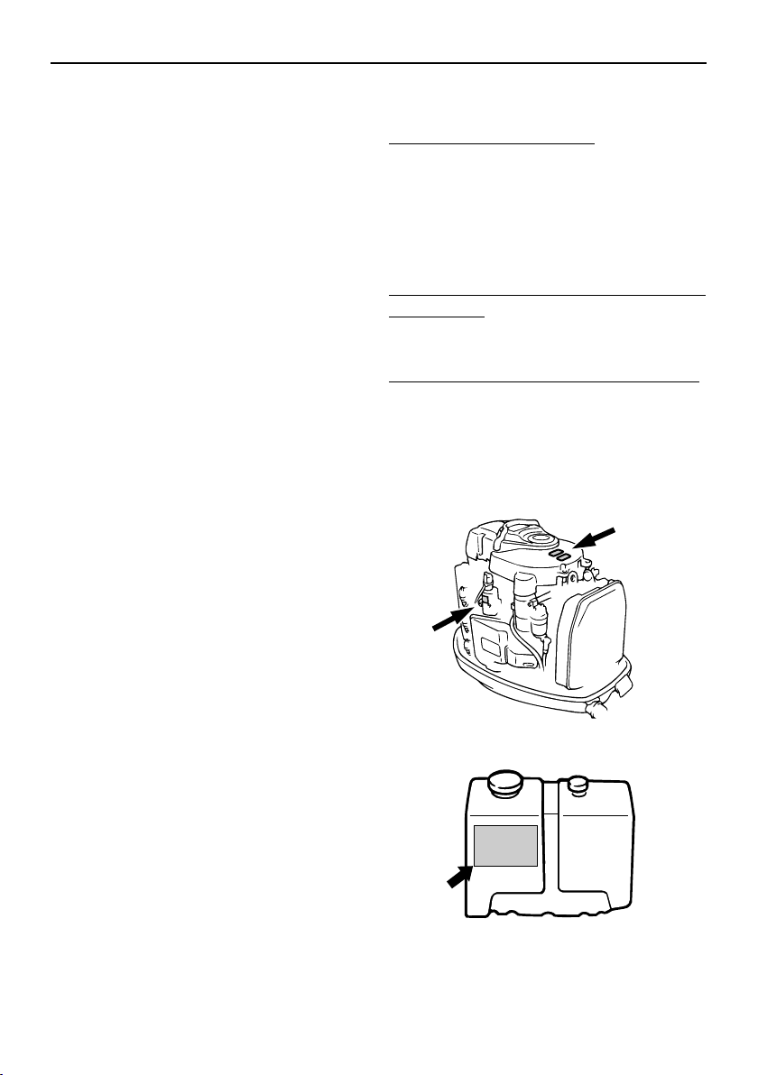
Outboard motor serial number
The outboard motor serial number is
stamped on the label attached to the port
side of the clamp bracket.
Record your outboard motor serial number in
the spaces provided to assist you in ordering
spare parts from your Yamaha dealer or for
reference in case your outboard motor is sto-
len.
EMU25190
Key number
If a main key switch is equipped with the mo-
tor, the key identification number is stamped
on your key as shown in the illustration.
Record this number in the space provided for
reference in case you need a new key.
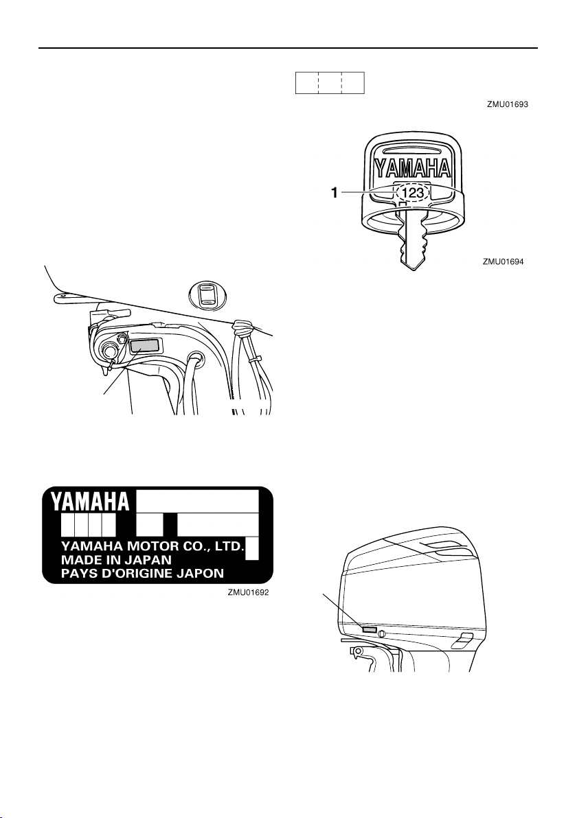
EMU25221
Emission control information
EMU25230
North American models
This engine conforms to U.S. Environmental
Protection Agency (EPA) regulations for ma-
rine SI engines. See the label affixed to your
engine for details.
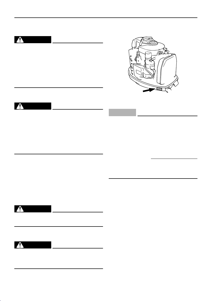
EMU31471
Approval label of emission control certif-
icate
This label is attached to the bottom cowling.
New Technology ; (HPDI) DFI/HO2S
1. Outboard motor serial number location
1
ZMU04426
1. Key number
1. Approval label location
1
ZMU04741
General information
2
EMU25262
Manufactured date label
This label is attached to the clamp bracket or
the swivel bracket.
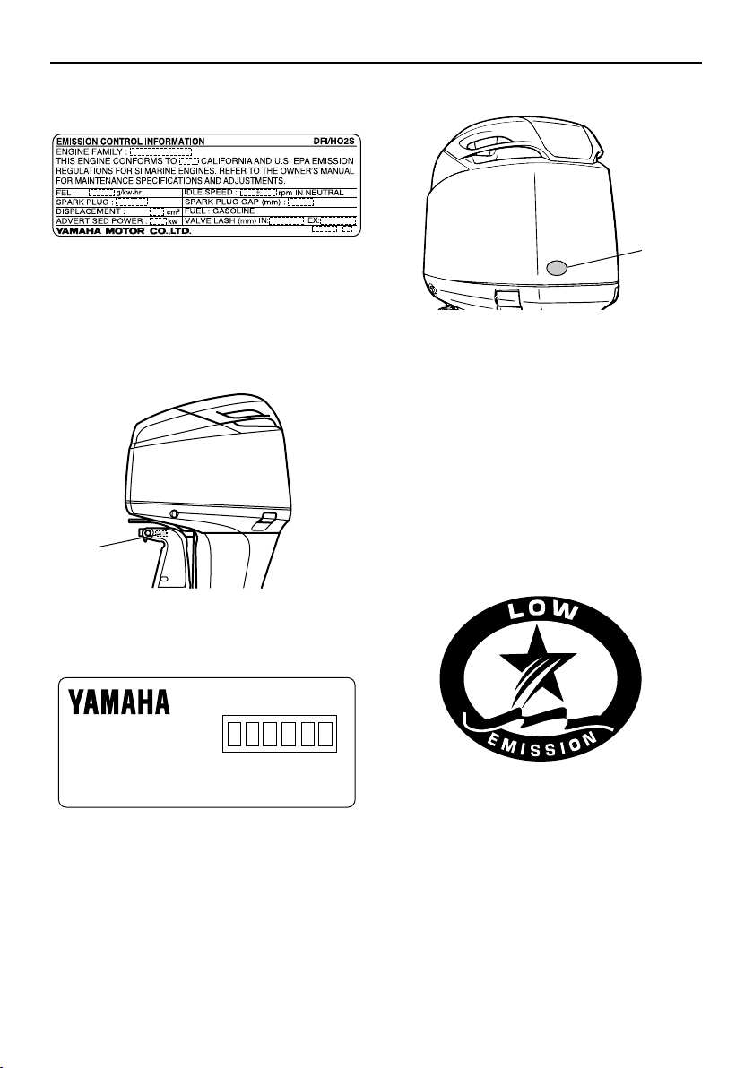
EMU25272
Star labels
Your outboard motor is labeled with a Cali-
fornia Air Resources Board (CARB) star la-
bel. See below for a description of your
particular label.
EMU25280
One Star—Low Emission
The one-star label identifies engines that
meet the Air Resources Board’s 2001 ex-
haust emission standards. Engines meeting
these standards have 75% lower emissions
than conventional carbureted two-stroke en-
gines. These engines are equivalent to the
U.S. EPA’s 2006 standards for marine en-
gines.
EMU25290
Two Stars—Very Low Emission
The two-star label identifies engines that
meet the Air Resources Board’s 2004 ex-
haust emission standards. Engines meeting
these standards have 20% lower emissions
than One Star-Low-Emission engines.
1. Manufactured date label location
ZMU05380
1
ZMU04726
Manufactured:
ZMU04346
1. Star labels location
1
ZMU04745
ZMU01702
General information
3
EMU25300
Three Stars—Ultra Low Emission
The three-star label identifies engines that
meet the Air Resources Board’s 2008 ex-
haust emission standards. Engines meeting
these standards have 65% lower emissions
than One Star-Low-Emission engines.
EMU25362
Safety information
●
Before mounting or operating the outboard
motor, read this entire manual. Reading it
should give you an understanding of the
motor and its operation.
●
Before operating the boat, read any own-
er’s or operator’s manuals supplied with it
and all labels. Be sure you understand
each item before operating.
●
Do not overpower the boat with this out-
board motor. Overpowering the boat could
result in loss of control. The rated power of
the outboard should be equal to or less
than the rated horsepower capacity of the
boat. If the rated horsepower capacity of
the boat is unknown, consult the dealer or
boat manufacturer.
●
Do not modify the outboard. Modifications
could make the motor unfit or unsafe to
use.
●
Incorrect propeller selection and incorrect
use may not only cause engine damage,
but also adversely affect fuel consumption.
Consult your dealer for correct use.
●
Never operate after drinking alcohol or tak-
ing drugs. About 50% of all boating fatali-
ties involve intoxication.
●
Have an approved personal flotation de-
vice (PFD) on board for every occupant. It
is a good idea to wear a PFD whenever
boating. At a minimum, children and non-
swimmers should always wear PFDs, and
everyone should wear PFDs when there
are potentially hazardous boating condi-
tions.
●
Gasoline is highly flammable, and its va-
pors are flammable and explosive. Handle
and store gasoline carefully. Make sure
there are no gas fumes or leaking fuel be-
fore starting the engine.
●
This product emits exhaust gases which
contain carbon monoxide, a colorless,
odorless gas which may cause brain dam-
age or death when inhaled. Symptoms in-
clude nausea, dizziness, and drowsiness.
Keep cockpit and cabin areas well ventilat-
ed. Avoid blocking exhaust outlets.
●
Check throttle, shift, and steering for prop-
er operation before starting the engine.
●
Attach the engine stop switch lanyard cord
to a secure place on your clothing, or your
arm or leg while operating. If you acciden-
tally leave the helm, the cord will pull from
ZMU01703
ZMU01704
General information
4
the switch, stopping the engine.
●
Know the marine laws and regulations
where you will be boating—and obey
them. For basic boating rules, see “Rules
of the road” on page 5.
●
Stay informed about the weather. Check
weather forecasts before boating. Avoid
boating in hazardous weather.
●
Tell someone where you are going: leave
a Float Plan with a responsible person. Be
sure to cancel the Float Plan when you re-
turn.
●
Use common sense and good judgment
when boating. Know your abilities, and be
sure you understand how your boat han-
dles under the different boating conditions
you may encounter. Operate within your
limits, and the limits of your boat. Always
operate at safe speeds, and keep a careful
watch for obstacles and other traffic.
●
Always watch carefully for swimmers dur-
ing the engine operation.
●
Stay away from swimming areas.
●
When a swimmer is in the water near you
shift into neutral and shut off the engine.
●
Do not illegally discard empty containers
used to replace or replenish oil. For the
correct processing of empty containers,
consult the dealer where you purchased
the oil.
●
When replacing oils used to lubricate the
product (engine or gear oil), be sure to
wipe away any spilt oil. Never pour oil with-
out using a funnel or similar device. If nec-
essary, verify the necessary replacement
procedure with the dealer.
●
Never illegally discard (dump) the product.
Yamaha recommends consulting the deal-
er on discarding the product.
Be informed about boating safety. Additional
publications and information can be obtained
from many organizations, including the fol-
lowing:
United States Coast Guard
Consumer Affairs Staff (G-BC)
Office of Boating, Public, and Consumer Af-
fairs
U.S. Coast Guard Headquarters
Washington, D.C. 20593-0001
Boating Safety Hotline: 1-800-368-5647
National Marine Manufacturers Associa-
tion (NMMA)
401 N. Michigan Ave.
Chicago, Il 60611
Marine Retailers Association of America
155 N. Michigan Ave.
Chicago, Il 60601
EMU25382
Important labels
EMU25395
Warning labels
ZMU04852
ZMU01948
General information
5
EMU25401
Label
WARNING
EWM01260
●
Be sure shift control is in neutral before
starting engine. (except 2HP)
●
Do not touch or remove electrical parts
when starting or during operation.
●
Keep hands, hair, and clothes away
from flywheel and other rotating parts
while engine is running.
EMU25413
Label (counter rotation models)
WARNING
EWM01281
Use only a counterclockwise rotation
propeller with this engine.
Counterclockwise propellers are marked
with a letter “L” after the size indication.
The wrong type of propeller could cause
the boat to go in an unexpected direction,
which could lead to an accident.
EMU25451
Label
ENGINE OIL ONLY
●
Pour the engine oil into this oil tank, not
gasoline.
RECOMMENDED OIL:
YAMALUBE 2 STROKE OUTBOARD OIL or
an equivalent TC-W3 certified ouboard oil.
WARNING
EWM01270
Do not add gasoline to the oil tank. Fire
explosion could result.
EMU30471
Label
WARNING
EWM01411
Hot surface under this cover during and
after operation. To avoid burns, do not
touch finned resistor with bare hands.
EMU25465
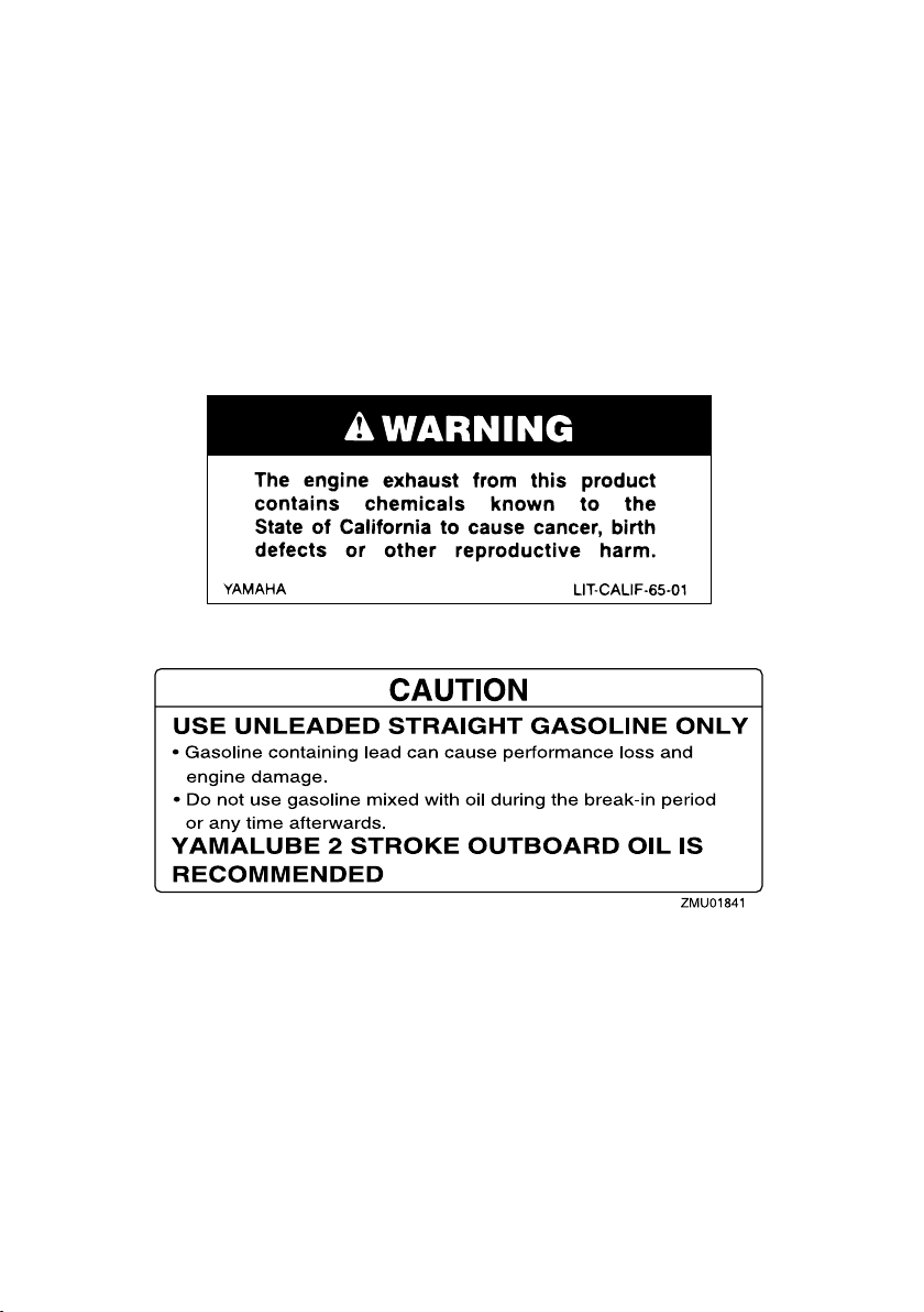
Caution labels
EMU30430
Label
CAUTION:
ECM01440
USE UNLEADED STRAIGHT GASOLINE
ONLY
●
Gasoline containing lead can cause
performance loss and engine damage.
●
Do not use gasoline mixed with oil (pre-
mix).
●
Use YAMALUBE 2-stroke outboard oil
or another 2-stroke engine oil with a
NMMA-certified TC-W3 rate.
Refer to Owner’s manual.
EMU25500
Basic boating rules (Rules of
the road)
Just as there are rules which apply when you
are driving on streets and high ways, there
are waterway rules which apply when you
are driving your boat. These rules are used
internationally, and are also enforced by the
United States Coast Guard and local agen-
cies. You should be aware of these rules,
and follow them whenever you encounter
another vessel on the water.
Several sets of rules prevail according to
geographic location, but are all basically the
same as the International Rules of the Road.
ZMU04435
General information
6
The rules presented here in your Owner’s
Manual are condensed, and have been pro-
vided for your convenience only. Consult
your local U.S. Coast Guard Auxiliary or De-
partment of Motor Vehicles for a complete
set of rules governing the waters in which
you will be using your boat.
EMU25510
Steering and sailing rules and sound
signals
Whenever two vessels on the water meet
one another, one vessel has the right-of-
way; it is called the “stand-on” vessel. The
vessel which does not have the right-of-way
is called the “give-way” or “burdened” vessel.
These rules determine which vessel has the
right-of-way, and what each vessel should
do.
Stand-on vessel
The vessel with the right-of-way has the duty
to continue its course and speed, except to
avoid an immediate collision. When you
maintain your direction and speed, the other
vessel will be able to determine how best to
avoid you.
Give-way vessel
The vessel which does not have the right-of-
way has the duty to take positive and timely
action to stay out of the way of the Stand-On
vessel. Normally, you should not cross in
front of the vessel with the right-of-way. You
should slow down or change directions brief-
ly and pass behind the other vessel. You
should always move in such a way that the
operator of the other vessel can see what
you are doing.
“The general prudential rule”
This rule is called Rule 2 in the International
Rules and says,
“In obeying and construing these rules due
regard shall be had to all dangers of naviga-
tion and collision, and to any special circum-
stances, which may render a departure from
the above rules necessary in order to avoid
immediate danger.”
In other words, follow the standard rules ex-
cept when a collision will occur unless both
vessels try to avoid each other. If that is the
case, both vessels become “Give-Way” ves-
sels.
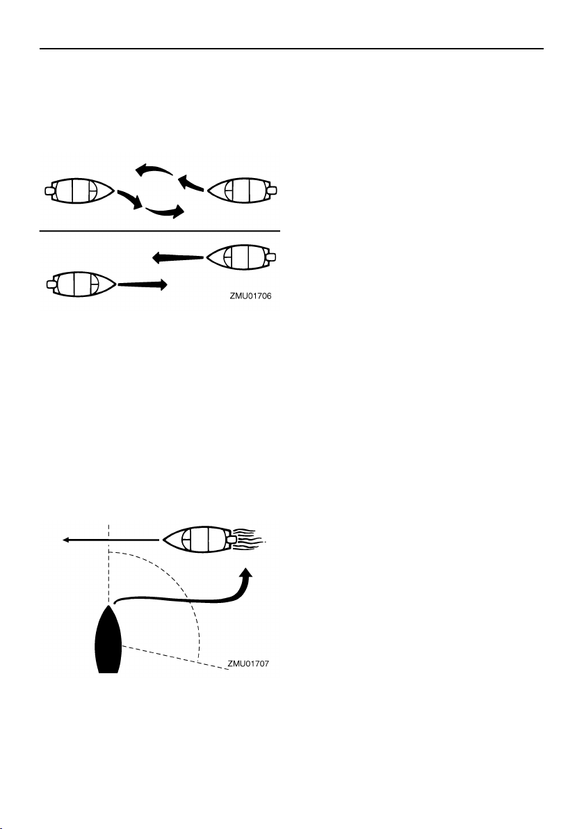
EMU25520
Rules when encountering vessels
There are three main situations which you
may encounter with other vessels which
could lead to a collision unless the Steering
Rules are followed:
Meeting:
(you are approaching another ves-
sel head-on)
Crossing:
(you are traveling across the oth-
er vessel’s path)
Overtaking:
(you are passing or being
passed by another vessel)
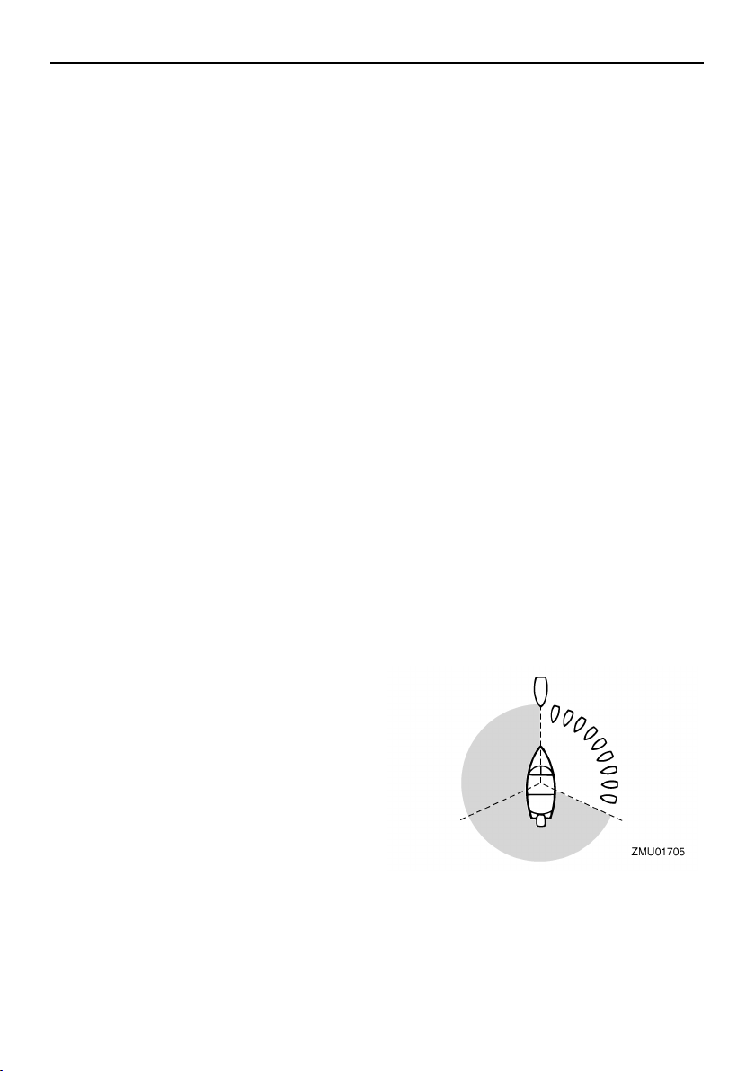
In the following illustration, your boat is in the
center. You should give the right-of-way to
any vessels shown in white area (you are the
Give-Way vessel). Any vessels in the shad-
ed area must yield to you (they are the Give-
Way vessels). Both you and the meeting
vessel must alter course to avoid each other.
Meeting
If you are meeting another power vessel
head on, and are close enough to run the risk
of collision, neither of you has the right-of-
General information
7
way! Both of you should alter course to avoid
an accident. You should keep the other ves-
sel on your port (left) side. This rule doesn’t
apply if both of you will clear one another if
you continue on your set course and speed.
Crossing
When two power driven vessels are crossing
each other’s path close enough to run the
risk of collision, the vessel which has the oth-
er on the starboard (right) side must keep out
of the way of the other. If the other vessel is
on your right, you must keep out of its way;
you are the Give-Way vessel. If the other
vessel is on your port (left) side, remember
that you should maintain course and direc-
tion, provided the other vessel gives you the
right-of-way as it should.
Overtaking
If you are passing another vessel, you are
the “Give-Way” vessel. This means that the
other vessel is expected to maintain its
course and speed. You must stay out of its
way until you are clear of it. Likewise, if an-
other vessel is passing you, you should
maintain your speed and direction so that the
other vessel can steer itself around you.
EMU25530
Other special situations
There are three other rules you should be
aware of when driving your boat around oth-
er vessels.
Narrow channels and bends
When navigating in narrow channels, you
should keep to the right when it is safe and
practical to do so. If the operator of a power-
driven vessel is preparing to go around a
bend that may obstruct the view of other wa-
ter vessels, the operator should sound a pro-
longed blast on the whistle (4 to 6 seconds).
If another vessel is around the bend, it too
should sound the whistle. Even if no reply is
heard, however, the vessel should still pro-
ceed around the bend with caution. If you
navigate such waters with your boat, you will
need to carry a portable air horn, available
from local marine supply stores.
Fishing vessel right-of-way
All vessels which are fishing with nets, lines
or trawls are considered to be “fishing ves-
sels” under the International Rules. Vessels
with trolling lines are not considered fishing
vessels. Fishing vessels have the right-of-
way regardless of position. Fishing vessels
cannot, however, impede the passage of
other vessels in narrow channels.
Sailing vessel right-of-way
Sailing vessels should normally be given the
right-of-way. The exceptions to this are:
1. When the sailing vessel is overtaking
the power-driven vessel, the power-driv-
en vessel has the right-of-way.
2. Sailing vessels should keep clear of any
fishing vessel.

General information
8
3. In a narrow channel, a sailing vessel
should not hamper the safe passage of
a power-driven vessel which can navi-
gate only in such a channel.
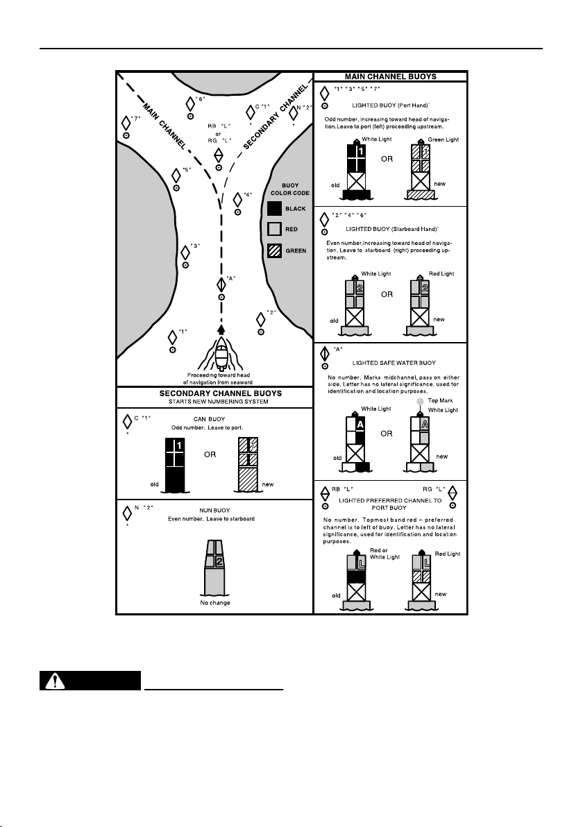
Reading buoys and other markers
The waters of the United states are marked
for safe navigation by the lateral system of
buoyage. Simply put, buoys and markers
have an arrangement of shapes, colors,
numbers and lights to show which side of the
buoy a boater should pass on when navigat-
ing in a particular direction. The markings on
these buoys are oriented from the perspec-
tive of being entered from seaward (the boat-
er is going towards the port). This means that
red buoys are passed on the starboard
(right) side when proceeding from open wa-
ter into port, and black buoys are to port (left)
side. When navigating out of port, your posi-
tion with respect to the buoys should be re-
versed; red buoys should be to port and
black buoys to starboard.
Many bodies of water used by boaters are
entirely within the boundaries of a particular
state. The Uniform State Waterway Marking
System has been devised for these waters.
This system uses buoys and signs with dis-
tinctive shapes and colors to show regulato-
ry or advisory information. These markers
are white with black letters and orange
boarders. They signify speed zones, restrict-
ed areas, danger areas, and general infor-
mation.
Remember, markings may vary by geo-
graphic location. Always consult local boat-
ing authorities before driving your boat in
unfamiliar waters.
General information
9
EMU25540
Fueling instructions
WARNING
EWM00010
GASOLINE AND ITS VAPORS ARE HIGH-
LY FLAMMABLE AND EXPLOSIVE!
●
Do not smoke when refueling, and keep
away from sparks, flames, or other
sources of ignition.
●
Stop engine before refueling.
●
Refuel in a well-ventilated area. Refuel
portable fuel tanks off the boat.
●
Take care not to spill gasoline. If gaso-
line spills, wipe it up immediately with
ZMU01708

General information
10
dry rags.
●
Do not overfill the fuel tank.
●
Tighten the filler cap securely after re-
fueling.
●
If you should swallow some gasoline,
inhale a lot of gasoline vapor, or get
gasoline in your eyes, get immediate
medical attention.
●
If any gasoline spills onto your skin, im-
mediately wash with soap and water.
Change clothing if gasoline spills on it.
●
Touch the fuel nozzle to the filler open-
ing or funnel to help prevent electro-
static sparks.
CAUTION:
ECM00010
Use only new clean gasoline which has
been stored in clean containers and is not
contaminated with water or foreign mat-
ter.
EMU25570
Gasoline
If knocking or pinging occurs, use a different
brand of gasoline or premium unleaded fuel.
Gasohol
There are two types of gasohol: gasohol con-
taining ethanol and that containing metha-
nol. Gasohol containing ethanol can be used
if ethanol content does not exceed 10% and
the fuel meets minimum octane ratings.
Yamaha does not recommended gasohol
containing methanol because it can cause
fuel system damage or engine performance
problems.
EMU25660
Engine oil
Use Yamalube 2-M outboard oil. If Ya-
malube 2-M is not available, use only anoth-
er outboard motor manufacturer’s factory-
brand oil with TC-W3 rating.
CAUTION:
ECM01290
Serious engine damage can result from
the use of lower quality oil, including
some commonly available oil brands with
“TC-W3” on their label. To avoid the risk,
use only Yamalube 2-M or, if necessary,
another outboard motor manufacturer’s
factory-brand TC-W3 oil.
EMU25700
Battery requirement
CAUTION:
ECM01060
Do not use a battery that does not meet
the specified capacity. If a battery which
does not meet specifications is used, the
electric system could perform poorly or
be overloaded, causing electric system
damage.
For electric start models, choose a battery
which meets the following specifications.
Recommended gasoline:
Regular unleaded gasoline with a min-
imum octane rating of 86 (Pump Oc-
tane Number) = (R+M)/2
Recommended engine oil:
YAMALUBE 2 STROKE OUTBOARD
OIL
General information
11
EMU25711
Battery specifications
NOTE:
The engine cannot be started if battery volt-
age is too low.
EMU25742
Propeller selection
The performance of your outboard motor will
be critically affected by your choice of propel-
ler, as an incorrect choice could adversely
affect performance and could also seriously
damage the motor. Engine speed depends
on the propeller size and boat load. If engine
speed is too high or too low for good engine
performance, this will have an adverse effect
on the engine.
Yamaha outboard motors are fitted with pro-
pellers chosen to perform well over a range
of applications, but there may be uses where
a propeller with a different pitch would be
more appropriate. For a greater operating
load, a smaller-pitch propeller is more suit-
able as it enables the correct engine speed
to be maintained. Conversely, a larger-pitch
propeller is more suitable for a smaller oper-
ating load.
Yamaha dealers stock a range of propellers,
and can advise you and install a propeller on
your outboard that is best suited to your ap-
plication.
NOTE:
Select a propeller which will allow the engine
to reach the middle or upper half of the oper-
ating range at full throttle with the maximum
boat load. If operating conditions such as
light boat loads then allow the engine r/min to
rise above the maximum recommended
range, reduce the throttle setting to maintain
the engine in the proper operating range.
For instructions on propeller removal and in-
stallation, see page 66.
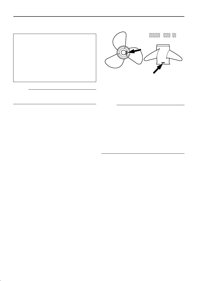
EMU25770
Start-in-gear protection
Yamaha outboard motors or Yamaha-ap-
proved remote control units are equipped
with start-in-gear protection device(s). This
feature permits the engine to be started only
when it is in neutral. Always select neutral
before starting the engine.
Minimum cold cranking amps (CCA/
SAE):
512.0 A
Minimum marine cranking amps (MCA/
ABYC):
675.0 A
Minimum reserve capacity (RC/SAE):
182 minutes
1. Propeller diameter in inches
2. Propeller pitch in inches
3. Type of propeller (propeller mark)
ZMU04608
-
x
123
12
Basic components
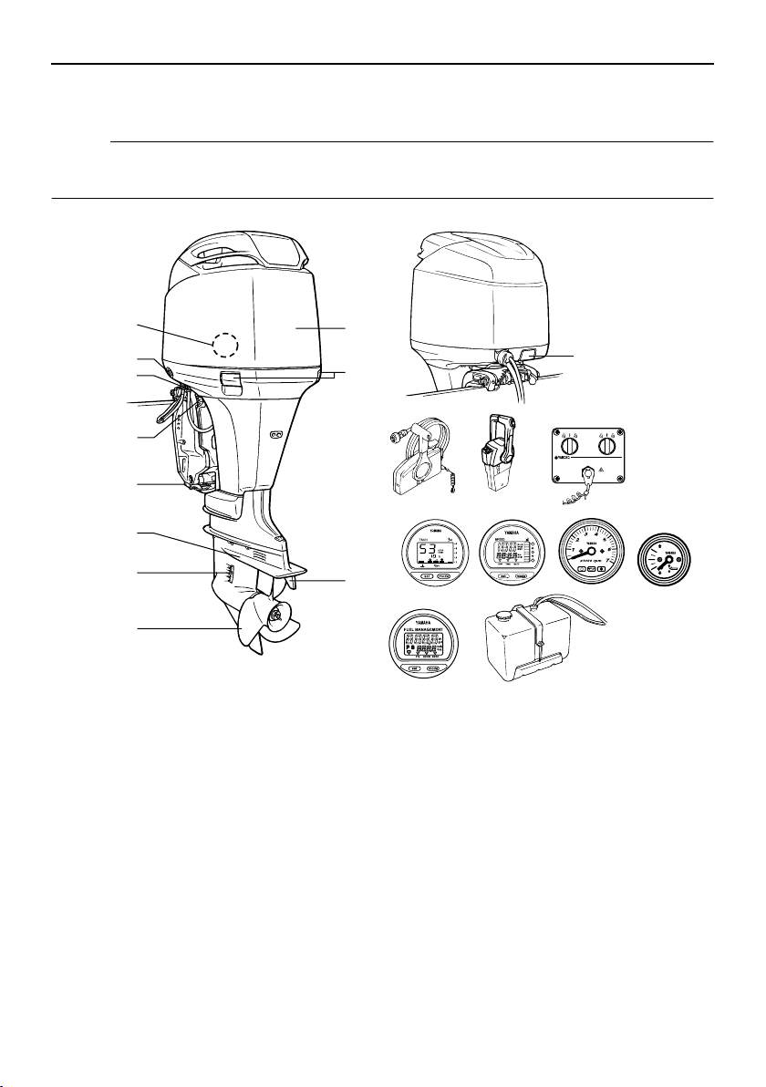
EMU25799
Main components
NOTE:
* May not be exactly as shown; also may not be included as standard equipment on all mod-
els.
Z200, LZ200
15
16
14
12 13
19
1
2
3
4
9
10
8
6
5
7
2
20
17
18
11
ZMU04850
1. Top cowling
2. Top cowling lock lever(s)
3. Trim tab (anode)
4. Propeller*
5. Cooling water inlet
6. Anti-cavitation plate
7. Anode
8. Tilt support lever
9. Flushing device
10. Power trim and tilt switch
11. Water separator
12. Remote control box (side mount type)*
13. Remote control box (binnacle mount type)*
14. Switch panel (for use with binnacle type)*
15. Digital tachometer*
16. Digital speedometer*
17. Tachometer*
18. Trim meter*
19. Fuel management meter*
20. Remote oil tank
Basic components
13
EMU26180
Remote control
The remote control lever actuates both the
shifter and the throttle. The electrical switch-
es are mounted on the remote control box.
1
4
6
3
2
5
ZMU05429
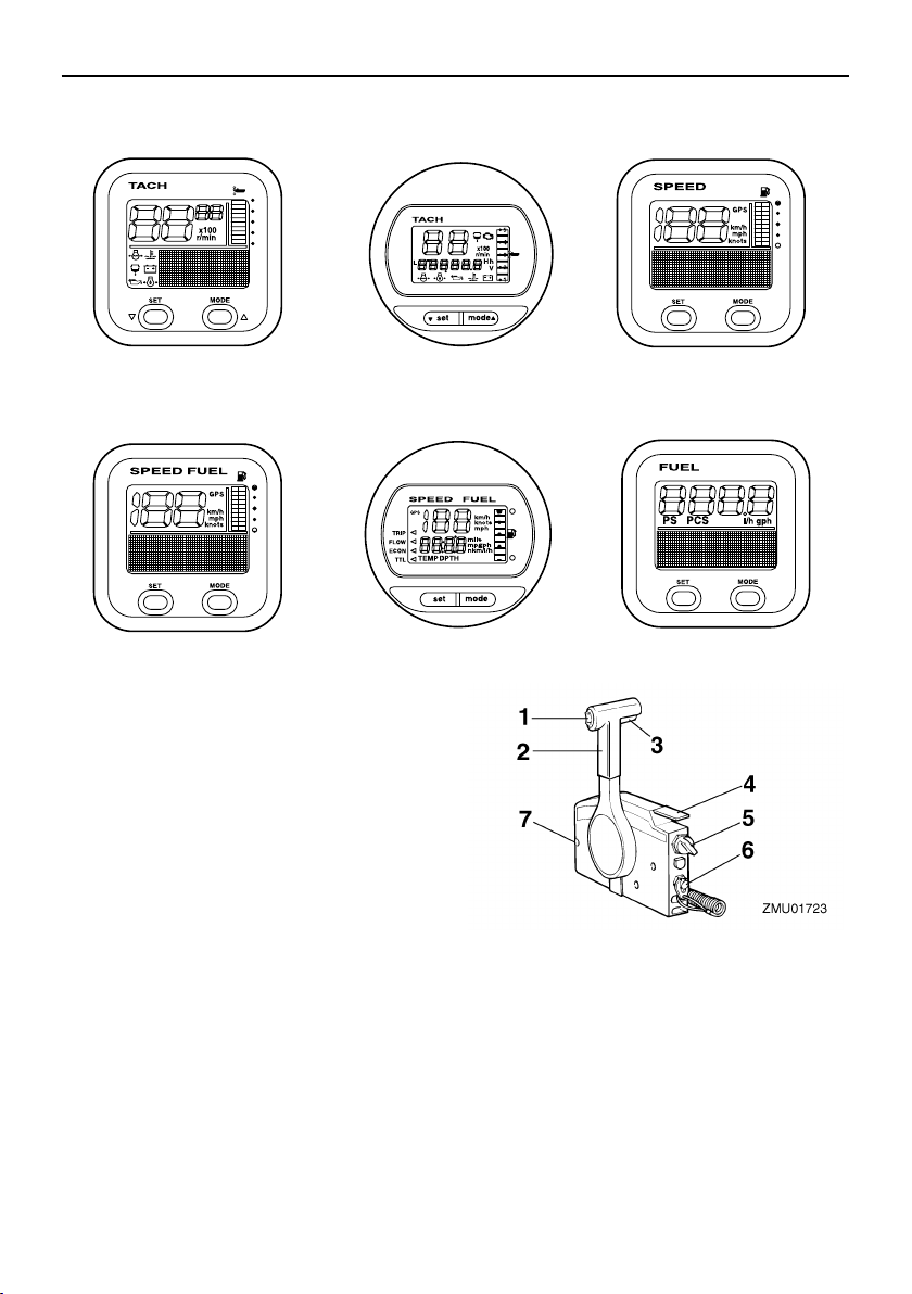
1. Tachometer unit (Square type)*
2. Tachometer unit (Round type)*
3. Speedometer unit (Square type)*
4. Speed & fuel meter unit (Square type)*
5. Speed & fuel meter unit (Round type)*
6. Fuel management meter (Square type)*
1. Power trim and tilt switch
2. Remote control lever
3. Neutral interlock trigger
4. Neutral throttle lever
5. Main switch / choke switch
6. Engine stop lanyard switch
7. Throttle friction adjuster
Basic components
14
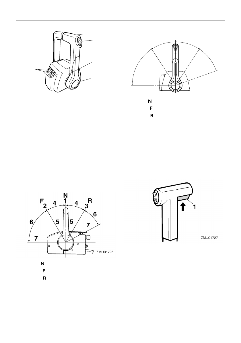
EMU26190
Remote control lever
Moving the lever forward from the neutral po-
sition engages forward gear. Pulling the le-
ver back from neutral engages reverse. The
engine will continue to run at idle until the le-
ver is moved about 35° (a detent can be felt).
Moving the lever farther opens the throttle,
and the engine will begin to accelerate.
EMU26201
Neutral interlock trigger
To shift out of neutral, first pull the neutral in-
terlock trigger up.
EMU26211
Neutral throttle lever
To open the throttle without shifting into ei-
ther forward or reverse, put the remote con-
trol lever in the neutral position and lift the
neutral throttle lever.
1. Remote control lever
2. Power trim and tilt switch
3. Free accelerator
4. Throttle friction adjuster
1. Neutral “”
2. Forward “”
3. Reverse “”
4. Shift
5. Fully closed
6. Throttle
7. Fully open
2
3
2
1
4
ZMU04569
1. Neutral “”
2. Forward “”
3. Reverse “”
4. Shift
5. Fully closed
6. Throttle
7. Fully open
1. Neutral interlock trigger
N
1
F
7
6
2
R
3
4
4
6
5
7
5
ZMU04573
Basic components
15
NOTE:
The neutral throttle lever will operate only
when the remote control lever is in neutral.
The remote control lever will operate only
when the neutral throttle lever is in the closed
position.
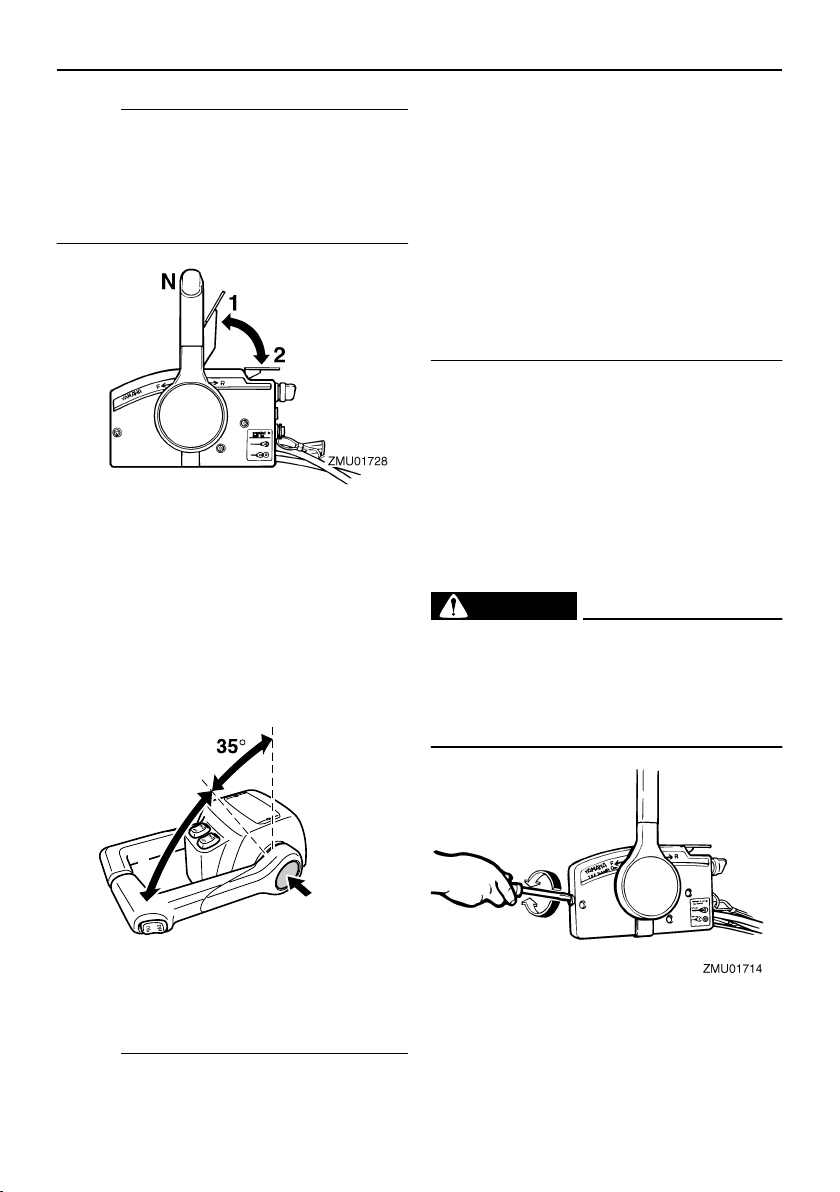
EMU26232
Free accelerator
To open the throttle without shifting into ei-
ther forward or reverse, push the free accel-
erator button and move the remote control
lever.
NOTE:
●
The free accelerator button can only be
used when the remote control lever is in
the neutral position.
●
After the button is pushed, the throttle be-
gins to open after the remote control lever
is moved at least 35°.
●
After using the free accelerator, return the
remote control lever to the neutral position.
The free accelerator button will return au-
tomatically to its set position. The remote
control will then engage forward and re-
verse normally.
EMU25971
Throttle friction adjuster
A friction device provides adjustable resis-
tance to movement of the throttle grip or the
remote control lever, and can be set accord-
ing to operator preference.
To increase resistance, turn the adjuster
clockwise. To decrease resistance, turn the
adjuster counterclockwise.
WARNING
EWM00031
Do not overtighten the friction adjuster. If
there is too much resistance, it could be
difficult to move the remote control lever
or throttle grip, which could result in an
accident.
1. Fully open
2. Fully closed
1. Fully open
2. Fully closed
3. Free accelerator
1
3
2
ZMU04575
Basic components
16
When constant speed is desired, tighten the
adjuster to maintain the desired throttle set-
ting.
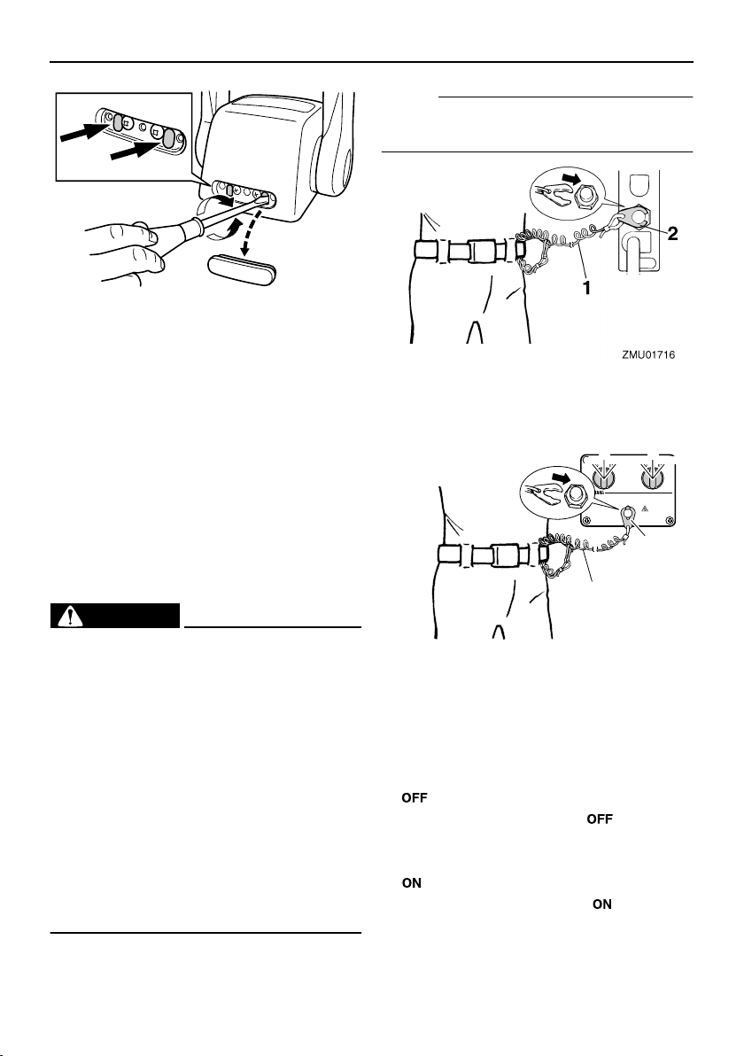
EMU25990
Engine stop lanyard switch
The lock plate must be attached to the en-
gine stop switch for the engine to run. The
lanyard should be attached to a secure place
on the operator’s clothing, or arm or leg.
Should the operator fall overboard or leave
the helm, the lanyard will pull out the lock
plate, stopping ignition to the engine. This
will prevent the boat from running away un-
der power.
WARNING
EWM00120
●
Attach the engine stop switch lanyard
to a secure place on your clothing, or
your arm or leg while operating.
●
Do not attach the lanyard to clothing
that could tear loose. Do not route the
lanyard where it could become entan-
gled, preventing it from functioning.
●
Avoid accidentally pulling the lanyard
during normal operation. Loss of en-
gine power means the loss of most
steering control. Also, without engine
power, the boat could slow rapidly. This
could cause people and objects in the
boat to be thrown forward.
NOTE:
The engine cannot be started with the lock
plate removed.
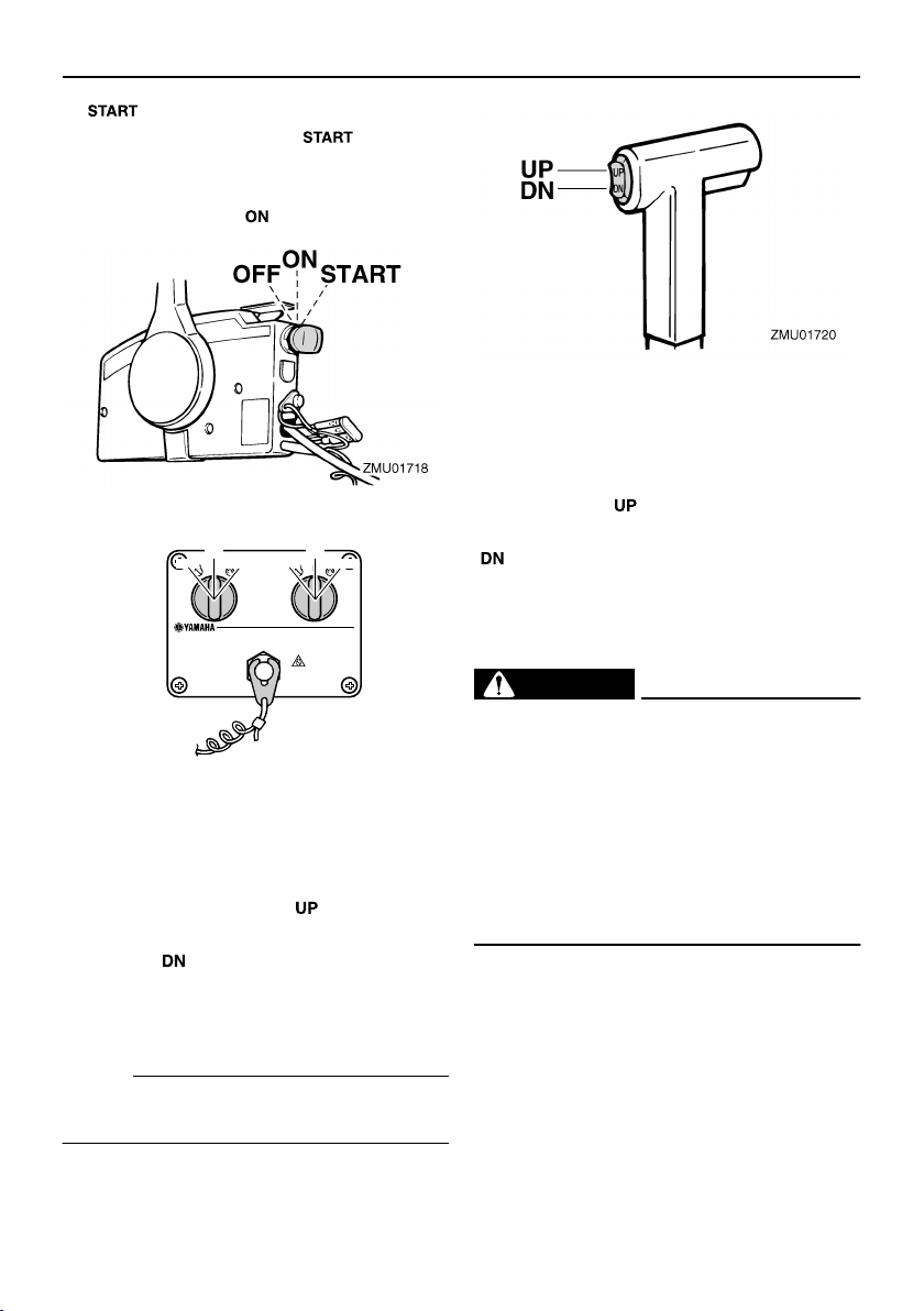
EMU26090
Main switch
The main switch controls the ignition system;
its operation is described below.
●
“”
(off)
With the main switch in the “” (off) posi-
tion, the electrical circuits are off, and the key
can be removed.
●
“”
(on)
With the main switch in the “” (on) posi-
tion, the electrical circuits are on, and the key
cannot be removed.
ZMU04646
1. Lanyard
2. Lock plate
1. Lanyard
2. Lock plate
ON
START
OFF
ON
START
OFF
1
ZMU04564
2
Basic components
17
●
“”
(start)
With the main switch in the “” (start) po-
sition, the starter motor turns to start the en-
gine. When the key is released, it returns
automatically to the “” (on) position.
EMU26141
Power trim and tilt switch on remote
control or tiller handle
The power trim and tilt system adjusts the
outboard motor angle in relation to the tran-
som. Pressing the switch “” (up) trims the
outboard motor up, then tilts it up. Pressing
the switch “” (down) tilts the outboard mo-
tor down and trims it down. When the switch
is released, the outboard motor will stop in its
current position.
NOTE:
For instructions on using the power trim and
tilt switch, see pages 47 and 49.
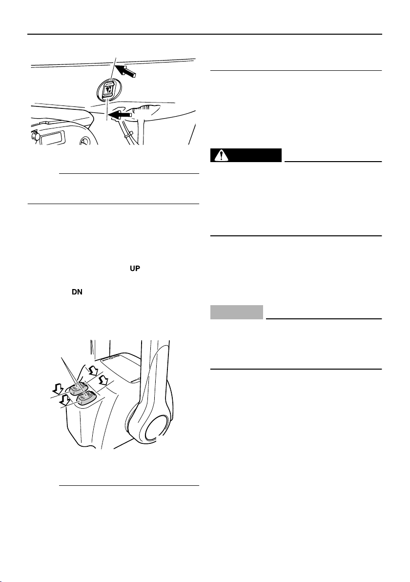
EMU26151
Power trim and tilt switch on bottom
engine cowling
The power trim and tilt switch is located on
the side of the bottom engine cowling. Press-
ing the switch “” (up) trims the outboard
motor up, then tilts it up. Pressing the switch
“” (down) tilts the outboard motor down
and trims it down. When the switch is re-
leased, the outboard motor will stop in its
current position.
WARNING
EWM01030
Use the power trim and tilt switch located
on the bottom engine cowling only when
the boat is at a complete stop with the en-
gine off. Attempting to use this switch
while the boat is moving could increase
the risk of falling overboard and could
distract the operator, increasing the risk
of collision with another boat or an obsta-
cle.
ON
OFF
START
ON
OFF
START
ZMU04566
Basic components
18
NOTE:
For instructions on using the power trim and
tilt switch, see page 49.
EMU26161
Power trim and tilt switches (twin
binnacle type)
The power trim and tilt system adjusts the
outboard motor angle in relation to the tran-
som. Pushing the switch “” (up) trims the
outboard motor up, then tilts it up. Pressing
the switch “” (down) tilts the outboard mo-
tor down and trims it down. When the switch
is released, the outboard motor will stop in its
current position.
NOTE:
●
On the dual engine control, the switch on
the remote control grip controls both out-
board motors at the same time.
●
For instructions on using the power trim
and tilt switches, see pages 47 and 49.
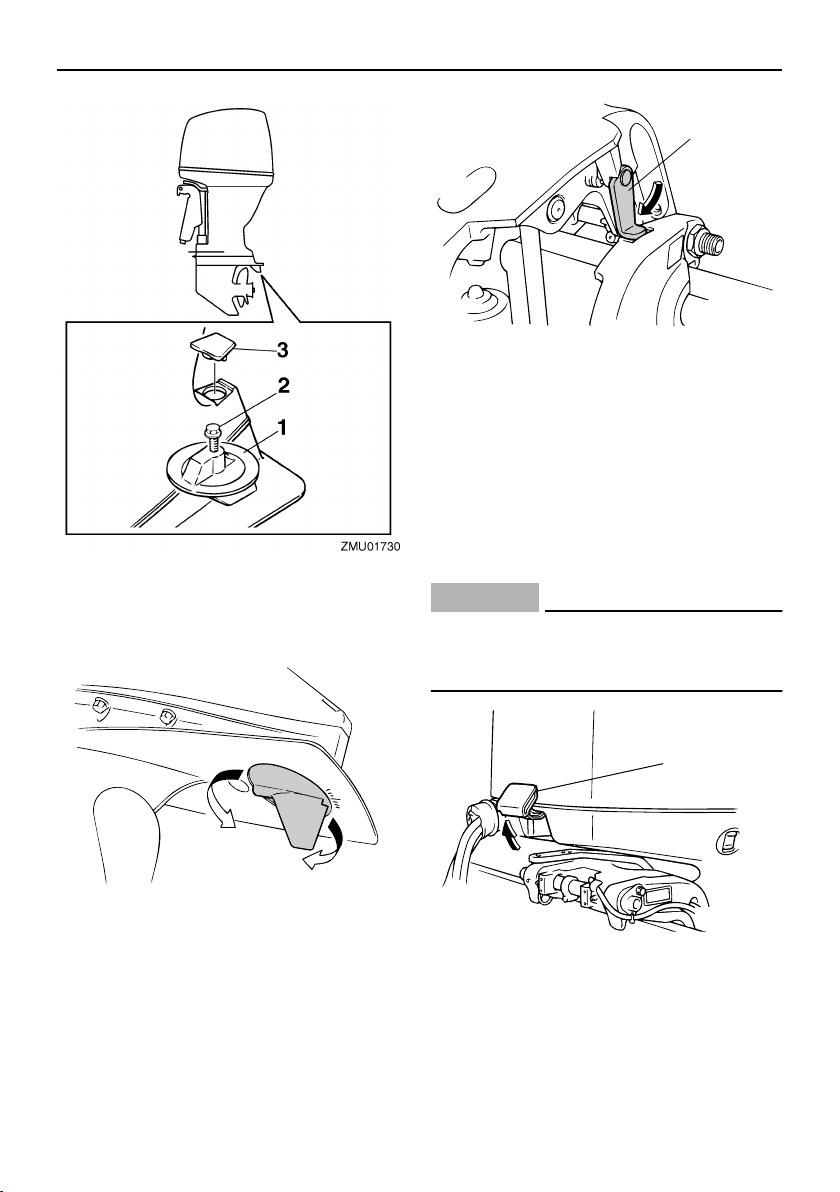
EMU26241
Trim tab with anode
The trim tab should be adjusted so that the
steering control can be turned to either the
right or left by applying the same amount of
force.
WARNING
EWM00840
An improperly adjusted trim tab could
cause difficult steering. Always test run
after the trim tab has been installed or re-
placed to be sure steering is correct. Be
sure you have tightened the bolt after ad-
justing the trim tab.
If the boat tends to veer the left (port side),
turn the trim tab rear end to the port side “A”
in the figure. If the boat tends to veer the right
(starboard side), turn the trim tab end to the
starboard side “B” in the figure.
CAUTION:
ECM00840
The trim tab also serves as an anode to
protect the engine from electrochemical
corrosion. Never paint the trim tab as it
will become ineffective as an anode.
1. Power trim and tilt switch
UP
DN
ZMU03985
ZMU04601
DN
UP
1
Basic components
19
EMU26340
Tilt support lever for power trim and
tilt or hydro tilt model
To keep the outboard motor in the tilted up
position, lock the tilt support lever to the
clamp bracket.
EMU26391
Top cowling lock levers
To remove the outboard motor top cowling,
pull up the front and rear lock levers. Then lift
off the cowling. When the cowling, check to
be sure it fits properly in the rubber seal.
Then lock the cowling again by moving the
levers downward.
CAUTION:
ECM00550
The air intake grille on the top cowling is
not designed as a handle and could break
if used as such.
1. Trim tab
2. Bolt
3. Cap
A
B
ZMU01863
1. Tilt support lever
1. Top cowling lock lever(s)
ZMU03979
1
ZMU03986
1
Basic components
20
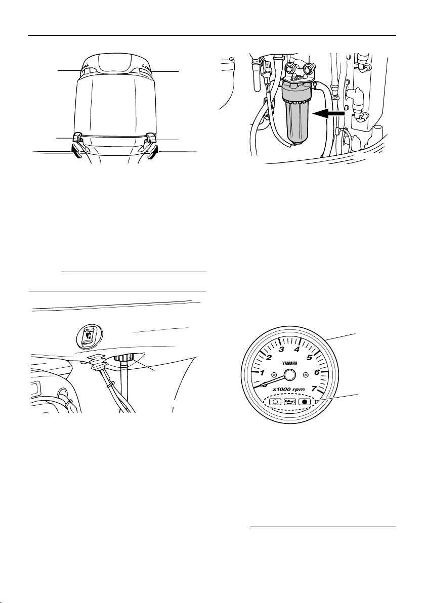
EMU26460
Flushing device
This device is used to clean the cooling wa-
ter passages of the motor using a garden
hose and tap water.
NOTE:
For details on usage, see page 58.
EMU31702
Water separator
This engine has a combination fuel filter/wa-
ter separator and associated warning sys-
tem. If water separated from the fuel
exceeds a specific volume, the warning de-
vice will activate.
Activation of warning device
●
The water separator warning indicator will
blink.
●
The buzzer will sound intermittently only
when the gear shift is in neutral.
●
If the warning system has activated, stop
the engine and consult a Yamaha dealer
immediately.
EMU26470
Tachometer
This gauge shows the engine speed and has
the following functions.
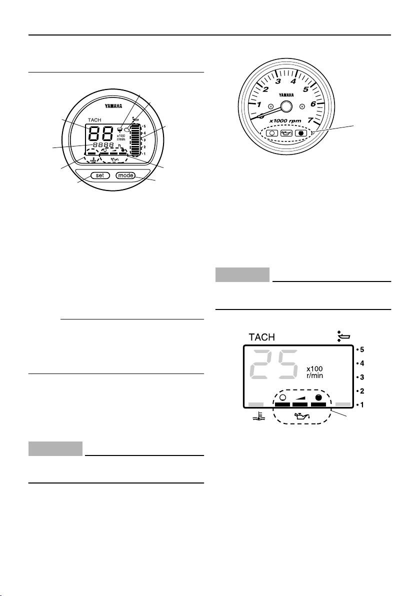
EMU26491
Digital tachometer
The tachometer shows the engine speed
and has the following functions.
NOTE:
All segments of the display will light momen-
1. Air intake grille
2. Top cowling lock lever(s)
1. Flushing device
1
2
1
2
ZMU04437
1
ZMU04011
1. Tachometer
2. Oil level indicator
ZMU05499
ZMU04577
1
2
Basic components
21
tarily after the main switch is turned on and
will return to normal thereafter.
NOTE:
The water separator and engine trouble
warning indicators only operate when the en-
gine is equipped with the appropriate func-
tions.
EMU26540
Oil level indicators (three indicators)
The indicators on the gauge show the status
of the oil level. For details on how to read the
indicators, see page 42.
CAUTION:
ECM00030
Do not operate the engine without oil. Se-
rious engine damage will occur.
EMU26550
Oil level indicator (digital type)
This indicator shows the engine oil level. If
the oil level falls below the lower limit, the
warning indicator will start to blink. For fur-
ther information, see page 34.
CAUTION:
ECM00030
Do not operate the engine without oil. Se-
rious engine damage will occur.
EMU26581
Overheat warning indicator (digital
type)
If the engine temperature rises too high, the
warning indicator will start to blink. For fur-
ther information on reading the indicator, see
1. Tachometer
2. Trim meter
3. Hour meter
4. Oil level indicator
5. Overheat warning indicator
6. Water separator warning indicator
7. Engine trouble warning indicator
8. Set button
9. Mode button
6
7
2
4
9
8
5
3
1
ZMU01958
1. Oil level indicators
1. Oil level indicator
ZMU04580
1
1
ZMU01867
Basic components
22
page 33.
CAUTION:
ECM00050
Do not continue to run the engine if the
overheat warning indicator is on. Serious
engine damage will occur.
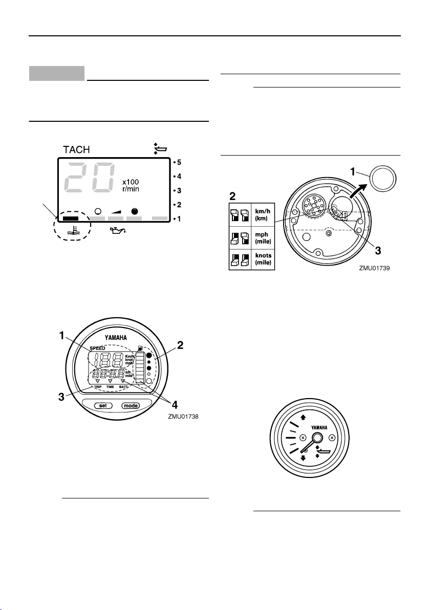
EMU26600
Speedometer (digital type)
This gauge shows the boat speed.
NOTE:
After the main switch is first turned on, all
segments of the display come on as a test.
After a few seconds, the gauge will change
to normal operation. Watch the gauge when
turning on the main switch to make sure all
segments come on.
NOTE:
The speedometer displays km/h, mph, or
knots, according to operator preference. Se-
lect the desired unit of measurement by set-
ting the selector switch on the back of the
gauge. See the illustration for settings.
EMU26610
Trim meter
This gauge shows the trim angle of your out-
board motor.
NOTE:
Memorize the trim angles that work best for
your boat under different conditions. Adjust
the trim angle to the desired setting with the
1. Overheat warning indicator
1. Speedometer
2. Fuel gauge
3. Trip meter/clock/voltmeter
4. Warning indicator(s)
1
ZMU01868
1. Cap
2. Selector switch (for speed unit)
3. Selector switch (for fuel sensor)
ZMU04581
Basic components
23
power trim and tilt switch.
EMU26620
Trim meter (digital type)
This meter shows the trim angle of your out-
board motor.
NOTE:
●
Memorize the trim angles that work best
for your boat under different conditions.
Adjust the trim angle to the desired using
the power trim and tilt switch.
●
If the trim angle of your motor exceeds the
trim operating range, the top segment on
the trim meter display will blink.
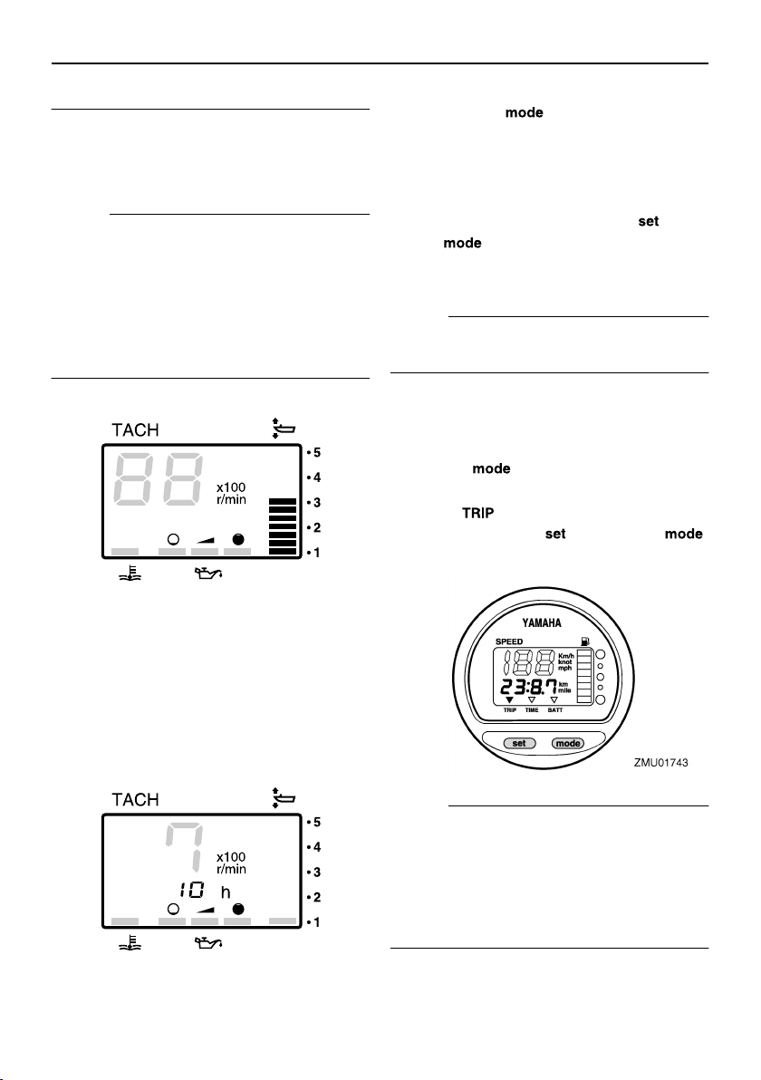
EMU26650
Hour meter (digital type)
This meter shows the number of hours the
engine has been run. It can be set to show
the total number of hours or the number of
hours for the current trip. The display can
also be turned on and off.
●
Changing the display format
●
Pressing the “” (mode) button chang-
es the display format in the following pat-
tern:
●
Total hours
→
Trip hours
→
Display off
●
Resetting the trip hours
●
Simultaneously pressing the “” (set)
and “” (mode) buttons for more than
1 second while the trip hours are displayed
resets the trip counter to 0 (zero).
NOTE:
The total number of hours the engine has
been run cannot be reset.
EMU26690
Trip meter
This gauge displays the distance the boat
has traveled since the gauge was last reset.
Press the “” (mode) button repeatedly
until the indicator on the face of the gauge
points to “” (trip). To reset the trip meter
to zero, press the “” (set) and “”
(mode) buttons at the same time.
NOTE:
●
The trip distance is shown in kilometers or
miles depending upon the unit of measure-
ment selected for the speedometer.
●
The trip distance is kept in memory by bat-
tery power. The stored data will be lost if
the battery is disconnected.
ZMU01869
ZMU01870
Basic components
24
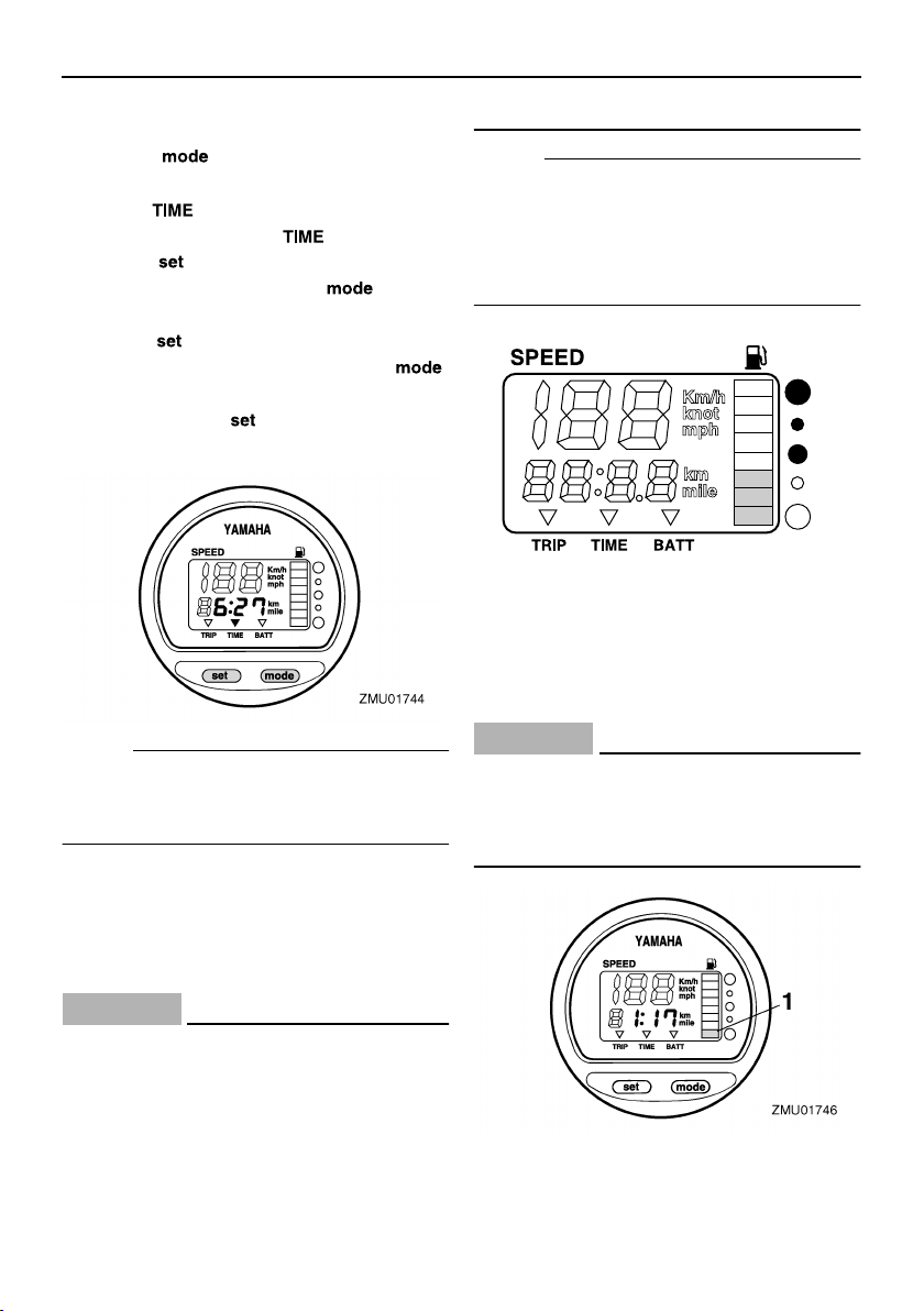
EMU26700
Clock
Press the “” (mode) button repeatedly
until the indicator on the face of the gauge
points to “” (time). To set the clock, be
sure the gauge is in the “” (time) mode.
Press the “” (set) button; the hour display
will begin blinking. Press the “” (mode)
button until the desired hour is displayed.
Press the “” (set) button again, the minute
display will begin blinking. Press the “”
(mode) button until the desired minute is dis-
played. Press the “” (set) button again to
start the clock.
NOTE:
The clock operates on battery power. Dis-
connecting the battery will stop the clock.
Reset the clock after connecting the battery.
EMU26710
Fuel gauge
The fuel level is indicated by eight segments.
When all segments are showing, the fuel
tank is full.
CAUTION:
ECM00860
The Yamaha fuel tank sensor differs from
conventional sensors. Incorrectly setting
the selector switch on the gauge will give
false readings. Consult your Yamaha
dealer on how to correctly set the selec-
tor switch.
NOTE:
The fuel level reading can be affected by the
position of the sensor in the fuel tank and the
attitude of the boat in the water. Operation
with bow-up trim or continuous turning can
give false readings.
EMU26720
Fuel warning indicator
If the fuel level decreases to one segment,
the fuel level warning segment will begin to
blink.
CAUTION:
ECM00880
Do not continue to operate the engine
with full throttle if a warning device has
activated. Get back to the port within troll-
ing engine speed.
1. Fuel level warning segment
ZMU01745
Loading...