


 Loading...
OWNER’S MANUAL
YZF-R6M
5EB-28199-21
EAU00000 |
INTRODUCTION |
|
|
|
|
|
|
Congratulations on your purchase of the Yamaha YZF-R6. This model is the result of Yamaha’s vast experience in the production of fine sporting, touring, and pacesetting racing machines. It represents the high degree of craftsmanship and reliability that have made Yamaha a leader in these fields.
This manual will give you an understanding of the operation, inspection, and basic maintenance of this motorcycle. If you have any questions about the operation or maintenance of your motorcycle, please consult a Yamaha dealer.
IMPORTANT MANUAL INFORMATION |
EAU00005 |
|
Particularly important information is distinguished in this manual by the following notations:
The Safety Alert Symbol means ATTENTION! BECOME ALERT! YOUR SAFETY IS
INVOLVED!
WARNING |
Failure to follow WARNING instructions could result in severe injury or death to the |
|
motorcycle operator, a bystander or a person inspecting or repairing the motorcycle. |
||
|
||
CAUTION: |
A CAUTION indicates special precautions that must be taken to avoid damage to the |
|
motorcycle. |
||
|
||
NOTE: |
A NOTE provides key information to make procedures easier or clearer. |
NOTE:
●This manual should be considered a permanent part of this motorcycle and should remain with it even if the motorcycle is subsequently sold.
●Yamaha continually seeks advancements in product design and quality. Therefore, while this manual contains the most current product information available at the time of printing, there may be minor discrepancies between your motorcycle and this manual. If there is any question concerning this manual, please consult your Yamaha dealer.

IMPORTANT MANUAL INFORMATION
EW000002
 WARNING
PLEASE READ THIS MANUAL CAREFULLY AND COMPLETELY BEFORE OPERATING THIS MOTORCYCLE.
IMPORTANT MANUAL INFORMATION
EAU00008
YZF-R6M
OWNER’S MANUAL
©1999 by Yamaha Motor Co., Ltd. 1st Edition, September 1999
All rights reserved. Any reprinting or unauthorized use without the written permission of Yamaha Motor Co., Ltd. is expressly prohibited.
Printed in Japan.

EAU00009 |
TABLE OF CONTENTS |
|
|
|
|
|
|
1 |
SAFETY INFORMATION |
|
1 |
|
|
|
|
|
|
|
|
2 |
DESCRIPTION |
|
2 |
|
|
|
|
|
|
|
|
3 |
INSTRUMENT AND CONTROL FUNCTIONS |
|
3 |
|
|
|
|
|
|
|
|
4 |
PRE-OPERATION CHECKS |
|
4 |
|
|
|
|
|
|
|
|
5 |
OPERATION AND IMPORTANT RIDING POINTS |
|
5 |
|
|
|
|
|
|
|
|
6 |
PERIODIC MAINTENANCE AND MINOR REPAIR |
|
6 |
|
|
|
|
|
|
|
|
7 |
MOTORCYCLE CARE AND STORAGE |
|
7 |
|
|
|
|
|
|
|
|
8 |
SPECIFICATIONS |
|
8 |
|
|
|
|
|
|
|
|
9 |
CONSUMER INFORMATION |
|
9 |
|
|
|
|
INDEX

|
|
|
SAFETY INFORMATION |
|||
|
|
|
|
|
|
|
|
|
|
|
|
|
|
|
|
Safe riding .......................................................................................... |
1-1 |
|
|
|
|
|
Protective apparel |
1-3 |
|
|
|
1 |
||||||
|
|
Modification |
1-3 |
|
||
|
|
|
|
|||
|
|
...................................................................Loading and accessories |
1-3 |
|
|
|
|
|
Gasoline and exhaust gas.................................................................. |
1-5 |
|
|
|
|
|
Location of the important labels ......................................................... |
1-7 |
|
|
|
|
|
|
|
|
|
|
|
|
|
|
|
|
|

SAFETY INFORMATION |
EAU00014 |
|
TWO-WHEELED MOTORCYCLES ARE SINGLE TRACK VEHICLES. THEIR SAFE USE AND OPERATION ARE DEPENDENT UPON THE USE OF PROPER RIDING TECHNIQUES AS WELL AS THE EXPERTISE OF THE OPERATOR.
1 EVERY OPERATOR SHOULD KNOW THE FOLLOWING REQUIREMENTS BEFORE RIDING. HE OR SHE SHOULD:
1.OBTAIN THOROUGH INSTRUCTIONS FROM A COMPETENT SOURCE ON ALL ASPECTS OF MOTORCYCLE OPERATION.
2.OBSERVE THE WARNINGS AND MAINTENANCE REQUIREMENTS IN THE OWNER’S MANUAL.
3.OBTAIN QUALIFIED TRAINING IN SAFE AND PROPER RIDING TECHNIQUES.
4.OBTAIN PROFESSIONAL TECHNICAL SERVICE AS INDICATED BY THE OWNER’S MANUAL AND/OR WHEN MADE NECESSARY BY MECHANICAL CONDITIONS.
Safe riding
1.Always make pre-operation checks. Careful checks may help prevent an accident.
2.This motorcycle is designed to carry the operator and a passenger.
3.The failure of motorists to detect and recognize motorcycles in traffic is the predominating cause of automobile/motorcycle accidents. Many accidents have been caused by an automobile driver who
did not see the motorcycle. Making yourself conspicuous appears to be very effective in reducing the chance of this type of accident.
Therefore:
a.Wear a brightly colored jacket.
b.Use extra caution when you approach and pass through intersections, since intersections are the most likely places for motorcycle accidents.
c.Ride where other motorists can see you. Avoid riding in another motorist’s “blind spot”.
1-1


 SAFETY INFORMATION
4.Many accidents involve inexperienced operators. In fact, many operators who have been involved in accidents do not even have a current motorcycle license.
a. |
Make sure you are qualified. Also, only lend your motorcycle to experienced operators. |
1 |
b. |
Know your skills and limits. Staying within your limits may help you to avoid an accident. |
c.We recommend that you practice riding your motorcycle where there is no traffic until you have become thoroughly familiar with your motorcycle and all of its controls.
5.Many motorcycle accidents have been caused by motorcycle operator errors. A typical error made by the operator is veering wide on a turn due to EXCESSIVE SPEED or undercornering (insufficient lean angle for the speed).
a.Always obey the speed limits and never travel faster than warranted by road and traffic conditions.
b.Always signal before turning or changing lanes. Make sure other motorists see you.
6.The operator’s and passenger’s posture are important for proper control.
a.The operator should keep both hands on the handlebars and both feet on the operator footrests during operation to maintain control of the motorcycle.
b.The passenger should always hold on to the operator, or the seat strap or grab bar if the motorcycle is so equipped, with both hands and keep both feet on the passenger footrests.
c.Never carry a passenger unless he or she can firmly place both feet on the passenger footrests.
7.Never ride under the influence of alcohol or drugs.
8.This motorcycle is designed for on-road use only. It is not suitable for off-road use.
1-2

 SAFETY INFORMATION
Protective apparel
|
The majority of fatalities from motorcycle accidents are the result of head injuries. The use of a safety |
||
1 |
helmet is the single most critical factor in the prevention or reduction of head injuries. |
||
1. |
Always wear an approved helmet. |
||
|
|||
|
|||
|
2. |
Wear a face shield or goggles. Wind on your unprotected eyes could contribute to an impairment of |
|
|
|
vision which could delay seeing a hazard. |
|
|
3. |
The use of heavy boots, jacket, trousers, gloves, etc. is effective in preventing or reducing abrasions |
|
|
|
or lacerations. |
|
|
4. |
Never wear loose fitting clothing. It could catch on the control levers, footrests, or wheels and cause |
|
|
|
injury or accident. |
|
|
5. |
Never touch the engine or exhaust system during or after operation. They become very hot and can |
|
|
|
cause burns. Always wear protective clothing that covers your legs, ankles, and feet. |
|
|
6. |
A passenger should also observe the above precautions. |
|
Modification
Modifications made to the motorcycle not approved by Yamaha, or the removal of original equipment, may render your motorcycle unsafe for use and may cause severe personal injury. Modifications may also make your motorcycle illegal to use.
Loading and accessories
Adding accessories or cargo to your motorcycle can adversely affect stability and handling if the weight distribution of the machine is changed. To avoid the possibility of an accident, extreme caution should be used if adding cargo or accessories to your motorcycle. Use extra care if riding a motorcycle which has added cargo or accessories. Here are some general guidelines to follow if loading cargo or adding accessories to your motorcycle:
1-3


 SAFETY INFORMATION
Loading
The total weight of the operator, passenger, accessories and cargo must not exceed the maximum load limit of 187 kg. 1 When loading within these weight limits, keep the following in mind:
1.Cargo and accessory weight should be kept as low and close to the motorcycle as possible. Be sure to distribute the weight as evenly as possible on both sides of the machine to minimize imbalance or instability.
2.Shifting weights can create a sudden imbalance. Make sure that accessories and cargo are securely attached to the motorcycle before riding. Recheck accessory mounts and cargo restraints frequently.
3.Never attach any large or heavy items to the handlebars, front forks, or front fender. These items, including such cargo as sleeping bags, duffle bags, or tents, can create unstable handling or slow steering response.
Accessories
Genuine Yamaha accessories have been specifically designed for use on this motorcycle. Since Yamaha cannot test all other accessories which may be available, you must personally be responsible for the proper selection, installation and use of non-Yamaha accessories. You should use extreme caution when selecting and installing any accessories.
Keep in mind these guidelines for mounting accessories in addition to those provided under “LOADING”.
1.Never install accessories or carry cargo that would impair the performance of your motorcycle. Carefully inspect the accessory before using it to make sure it does not in any way reduce ground clearance or cornering clearance, limit suspension travel, steering travel or control operation, or obscure lights or reflectors.
1-4

 SAFETY INFORMATION
a.Accessories fitted to the handlebar or the front fork area can create instability due to improper weight distribution or aerodynamic changes. If accessories are added to the handlebar or front
fork area, they must be as lightweight as possible and should be kept to a minimum.
1 b. Bulky or large accessories may seriously affect the stability of the motorcycle due to aerodynamic effects. Wind may attempt to lift the motorcycle, or the motorcycle may become unstable in cross winds. These accessories may also cause instability when being passed by or passing large vehicles.
c.Certain accessories can displace the operator from his or her normal riding position. This improper position limits the freedom of movement of the operator and may limit control ability. Therefore such accessories are not recommended.
2.Caution must be used if adding electrical accessories. If these accessories exceed the capacity of the motorcycle’s electrical system, an electric failure could result, which could cause a dangerous loss of lights or engine power.
Gasoline and exhaust gas
1.GASOLINE IS HIGHLY FLAMMABLE:
a.Always turn off the engine when refueling.
b.Take care not to spill any gasoline on the engine or exhaust system when refueling.
c.Never refuel while smoking or in the vicinity of an open flame.
2.Never start the engine or let it run for any length of time in a closed area. The exhaust fumes are poisonous and may cause loss of consciousness and death within a short time. Always operate your motorcycle in an area that has adequate ventilation.
3.Always turn off the engine before leaving the motorcycle unattended and remove the ignition key. When parking the motorcycle, note the following:
1-5

 SAFETY INFORMATION
a.The engine and exhaust system may be hot. Park the motorcycle in a place where pedestrians or children are not likely to touch these hot areas.
b.Do not park the motorcycle on a slope or soft ground; the motorcycle may fall over.
c. Do not park the motorcycle near a flammable source, e.g. a kerosene heater, or near an open 1 flame. The motorcycle could catch fire.
4.When transporting the motorcycle in another vehicle, be sure it is kept upright. If it should lean over, gasoline may leak out of the carburetor or fuel tank.
5.If you should swallow any gasoline, inhale a lot of gasoline vapor, or allow gasoline to get in your eyes, see your doctor immediately. If any gasoline spills on your skin or clothing, immediately wash it off with soap and water and change your clothes.
1-6


 SAFETY INFORMATION
EAU02977
Location of the important labels
Please read the following labels carefully before operating this motorcycle.
1
1
WARNING
Before you operate this vehicle, read the owner’s manual.
English |
3HP-21568-00 |
2
4AA-22259-40
1-7

|
DESCRIPTION |
|
|
Left view ............................................................................................. |
2-1 |
Right view........................................................................................... |
2-2 |
Controls/Instruments .......................................................................... |
2-3 |
2
DESCRIPTION |
EAU00026 |
|
Left view
2
1. Front fork compression damping force |
|
6. Rear shock absorber spring preload |
|
adjusting screw |
(page 3-18) |
adjusting ring |
(page 3-19) |
2. Front fork rebound damping force |
|
7. Rear shock absorber rebound damping |
|
adjusting screw |
(page 3-18) |
force adjusting knob |
(page 3-19) |
3. Front fork spring preload adjusting bolt |
(page 3-17) |
8. Shift pedal |
(page 3-11) |
4. Air filter |
(page 6-17) |
9. Coolant reservoir tank |
(page 6-13) |
5. Rear shock absorber compression |
|
10. Engine oil filter |
(page 6-11) |
damping force adjusting screw |
(page 3-20) |
|
|
2-1

DESCRIPTION
Right view
2
11. Luggage strap holders |
(page 3-22) |
12. Tool kit |
(page 6-1) |
13. Fuses |
(page 6-34) |
14. Rear brake fluid reservoir |
|
15. Radiator cap |
(page 6-14) |
16. Front brake fluid reservoir |
|
17. Rear brake pedal |
(page 3-12) |
2-2
DESCRIPTION
Controls/Instruments
2
18. Clutch lever |
(page 3-11) |
23. Tachometer |
(page 3-8) |
||||
19. Left handlebar switches |
(page 3-9) |
24. Right handlebar switches |
(page 3-10) |
||||
20. Starter (choke) “ |
|
|
|
” |
(page 3-14) |
25. Throttle grip |
(page 6-21) |
|
|
||||||
21. Digital speedometer |
(page 3-7) |
26. Front brake lever |
(page 3-11) |
||||
22. Main switch |
(page 3-1) |
|
|
||||
2-3
INSTRUMENT AND CONTROL FUNCTIONS
Main switch/steering lock...................................... |
3-1 |
Indicator lights ...................................................... |
3-2 |
Oil level/coolant temperature indicator light |
|
circuit check ........................................................ |
3-5 |
Fuel indicator light circuit check............................ |
3-6 |
Digital speedometer.............................................. |
3-7 |
Tachometer ........................................................... |
3-8 |
Diagnosis device................................................... |
3-9 |
Handlebar switches .............................................. |
3-9 |
Clutch lever ......................................................... |
3-11 |
Shift pedal........................................................... |
3-11 |
Front brake lever ................................................. |
3-11 |
Rear brake pedal ................................................ |
3-12 |
Fuel tank cap ..................................................... |
3-13 |
|
|||
Fuel .................................................................... |
3-13 |
|
|||
Starter (choke) “ |
|
” |
3-14 |
|
|
|
|
||||
Seats.................................................................. |
3-15 |
|
|||
Helmet holder..................................................... |
3-16 |
|
|||
Storage compartment |
3-16 |
|
|||
3 |
|||||
Front fork adjustment |
3-17 |
||||
|
|||||
.......................Rear shock absorber adjustment |
3-19 |
|
|||
Recommended combinations of the front fork |
|
|
|||
and the rear shock absorber settings............... |
3-21 |
|
|||
Luggage strap holders ....................................... |
3-22 |
|
|||
Sidestand ........................................................... |
3-22 |
|
|||
Sidestand/clutch switch operation check............ |
3-23 |
|
|||
INSTRUMENT AND CONTROL FUNCTIONS |
EAU00027 |
|
3
1. Push
2. Turn
EAU00029* |
EAU00040 |
Main switch/steering lock
The main switch controls the ignition and lighting systems. Its operation is described below.
EAU00030
ON
Electrical circuits are switched on, and the headlight, meter light, and taillight come on. The engine can be started. The key cannot be removed in this position.
EAU00038
LOCK
The steering is locked in this position and all electrical circuits are switched off. The key can be removed in this position.
To lock the steering, turn the handlebars all the way to the left. While pushing the key into the main switch, turn it from “OFF” to “LOCK” and remove it.
To release the lock, turn the key to “OFF” while pushing.
EW000016
 WARNING
@
Never turn the key to “OFF” or “LOCK” when the motorcycle is moving. The electrical circuits will be switched off which may result in loss of control or an accident. Be sure the motorcycle is stopped before turning the key to “OFF” or “LOCK”.
@
OFF
All electrical circuits are switched off. The key can be removed in this position.
3-1
INSTRUMENT AND CONTROL FUNCTIONS
1.Neutral indicator light “  ”
”
2.High beam indicator light “ ”
”
3.Turn indicator light “  ”
”
4.Fuel indicator light “  ”
”
EAU00057
Turn indicator light “  ”
”
This indicator flashes when the turn switch is moved to the left or right.
EAU01154
Fuel indicator light “ ” |
|
When the fuel level drops below ap- |
|
proximately 3.5 L, this light will come |
3 |
on. When this light comes on, fill the tank at the first opportunity. This light circuit can be checked by the procedure on page 3-6.
EAU00056
Indicator lights
EAU00061
Neutral indicator light “  ”
”
This indicator comes on when the transmission is in neutral.
EAU00063
High beam indicator light “  ”
”
This indicator comes on when the headlight high beam is used.
3-2

INSTRUMENT AND CONTROL FUNCTIONS
3
1.Oil level symbol “ 

 ”
”
2.Oil level/coolant temperature indicator light “  ”
”
3.Coolant temperature symbol “  ”
”
EAU01564
Oil level/coolant temperature indicator light “  ”
”
This indicator light has two functions.
●The light will come on and symbol “ 

 ” will flash if the engine oil level is low. If this symbol flashes, stop the engine immediately and fill it with oil to the specified level.
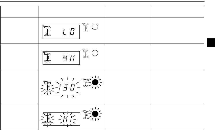
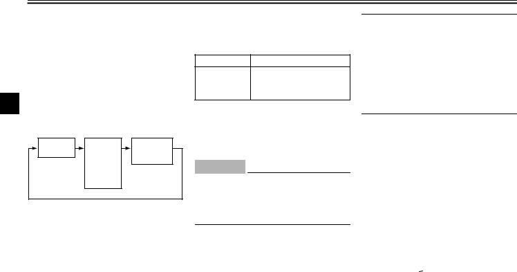
●The light will come on and symbol “  ” will flash if the coolant temperature is too high. The following chart shows the conditions of the indicator light, symbol and tem-
perature display in accordance to coolant temperature.
The light circuit can be checked by the procedure on page 3-5.
EC000118
CAUTION:
●Do not run the motorcycle until you know it has sufficient engine oil.
●Do not run the motorcycle if the engine is overheated.
NOTE:
Even if the oil is filled to the specified level, the indicator light may flicker when riding on a slope or during sudden acceleration or deceleration, but this is normal.
3-3
INSTRUMENT AND CONTROL FUNCTIONS
Coolant |
Display |
Conditions |
What to do |
|
temperature |
||||
|
|
|
||
0 °C ~ 40 °C |
˚C |
Symbol is on and “LO” is |
OK. Go ahead with riding. |
|
|
||||
|
displayed. |
|||
|
|
|
3
41 °C ~ 117 °C |
˚C |
Symbol is on and tempera- |
OK. Go ahead with riding |
|
|||
|
ture is displayed. |
||
|
|
|
|
|
|
|
Stop the motorcycle and allow it |
|
|
|
|
|
to idle until coolant temperature |
|
˚C |
Symbol |
and |
temperature |
goes down. |
|
If the temperature does not go |
|||||
118 °C ~ 140 °C |
flash. |
|
|
||
|
|
down, stop the engine. See “En- |
|||
|
Indicator light comes on. |
||||
|
gine overheating” in the trouble- |
||||
|
|
|
|
||
|
|
|
|
shooting chart on page 6-42 for |
|
|
|
|
|
instructions. |
|
˚C |
Symbol and message “HI” |
Stop the engine and allow it to |
|
cool. See “Engine overheating” |
|||
flash. |
|||
141 °C ~ |
in the troubleshooting chart on |
||
|
Indicator light comes on. |
||
|
page 6-42 for instructions. |
||
|
|
3-4
INSTRUMENT AND CONTROL FUNCTIONS
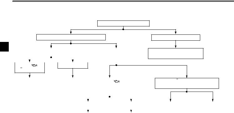
EAU02987
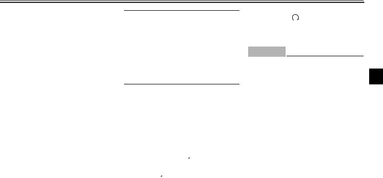
Oil level/coolant temperature indicator light circuit check
Turn the main switch to “ON”.
Indicator comes on. After a few seconds:
3
|
|
Indicator goes off. |
|
|
|
Indicator does not go off. |
||||
|
|
|
|
|
|
|
|
|
|
|
|
|
|
|
|
|
|
|
|
|
|
|
|
|
|
|
|
|
|
|
|
|
|
|
|
|
|
|
|
|
|
|
|
|
|
|
|
|
|
|
|
|
|
|
Symbol “ |
” or |
No symbol is on. |
|
|
|
|||||
|
|
|
||||||||
“ ” is on.
Indicator does not come on.
Have a Yamaha dealer inspect the electrical circuit.
Have a Yamaha |
|
OK. Go ahead |
|
|
If symbol “ |
” |
|
|
dealer inspect the |
|
with riding. |
|
|
is on, inspect the |
|
||
electrical circuit. |
|
|
|
|
oil level. |
|
|
|
|
|
|
|
|||||
|
|
|
|
|
|
|
|
|
|
|
|
|
|
|
|
|
|
|
|
|
|
|
|
|
|
|
|
|
|
|
|
|
|
|
|
If symbol “ ” is on, check the engine temperature. (See page 3-4.)
|
Oil level is OK. |
|
|
Oil level is low. |
||
|
|
|
|
|
|
|
|
|
|
|
|
||
|
|
|
|
|
|
|
Have a Yamaha dealer |
|
Supply |
||||
inspect the electrical |
|
recommended |
||||
circuit. |
|
engine oil. |
||||
|
|
|
|
|
|
|
If the engine is hot, |
|
If the engine |
allow it to cool and see |
|
temperature is |
“Engine overheating” |
|
normal, have a |
in the troubleshooting |
|
Yamaha dealer |
chart on page 6-42 for |
|
inspect the |
instructions. |
|
electrical circuit. |
|
|
|
3-5
INSTRUMENT AND CONTROL FUNCTIONS
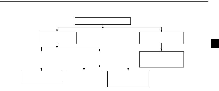
EAU01295
Fuel indicator light circuit check
Turn the main switch to “ON”.
Indicator comes on.
After a few seconds:
Indicator goes off. |
|
Indicator does not go off. |
|
|||
|
|
|
Inspect the fuel level. |
|
||
|
|
|
||||
|
|
|
|
|
|
|
|
|
|
|
|
|
|
|
|
|
|
|
|
|
Indicator does not come
on.
3
Have a Yamaha dealer inspect the electric circuit.
OK. Go ahead with riding.
Fuel level is OK. Have a Yamaha dealer inspect the electric circuit.
Fuel level is low. Supply recommended fuel.
3-6

INSTRUMENT AND CONTROL FUNCTIONS
3
1.Speedometer
2.Clock, odometer
3.“SELECT” button
4.“RESET” button
EAU01601
Digital speedometer
This speedometer is equipped with:
●an odometer
●two trip odometers
●a fuel reserve trip meter
●a clock
NOTE:
For UK and USA models only:
To change the speedometer display from kilometers to miles, press the “SELECT” button for at least two seconds.
Odometer and trip meter modes
Use the trip meters to estimate how far you can ride on a tank of fuel.
Use the fuel reserve trip meter to see the distance traveled from when the fuel level dropped to the reserve level.
Selecting a mode
Push the “SELECT” button to change between the odometer mode “ODO” and the trip odometer modes “TRIP 1” and “TRIP 2” in the following order:
“ODO” → “TRIP 1” → “TRIP 2” → “ODO”
If the fuel level indicator light comes on (see page 3-2), the odometer display will automatically change to the fuel reserve trip meter mode “TRIP F” and start counting the distance traveled from that point. Push the “SELECT” button to change between the fuel odometer, trip odometer and odometer modes in the following order:
“TRIP F” → “TRIP 1” → “TRIP 2” → “ODO” → “TRIP F”
Resetting a meter
To reset a trip odometer to 0.0, select it by pushing the “SELECT” button and push the “RESET” button for at least one second. To reset the fuel reserve trip meter, select it by pushing the “SELECT” button and push the “RESET” button for at least one second. The display will return to “TRIP 1”. If you do not reset the fuel reserve trip meter manually, it will automatically reset and return to “TRIP 1” after refueling and the motorcycle has traveled both 5 km and for approximately 3 minutes.
NOTE:
@
After the fuel reserve trip meter is reset, the display always returns to the “TRIP 1” mode. If “TRIP 2” was being used before the fuel reserve trip meter is reset, be sure to push the “SELECT” button to change back to the “TRIP 2” mode.
@
3-7
INSTRUMENT AND CONTROL FUNCTIONS
Clock mode
To change the display to the clock mode, push both the “SELECT” and “RESET” buttons.
To change the display back to the odometer mode, push the “RESET” button.
To set the clock
1.Push both the “SELECT” and “RESET” buttons for at least two seconds.
2.When the hour digits start flashing, push the “RESET” button to set the hours.
3.Push the “SELECT” button to change the minutes.
4.When the minute digits start flashing, push the “RESET” button to set the minutes.
5.Push the “SELECT” button to start the clock.
NOTE:
After setting the clock, be sure to push the “SELECT” button before turning the main switch to “OFF”, otherwise the clock will not be set.
3
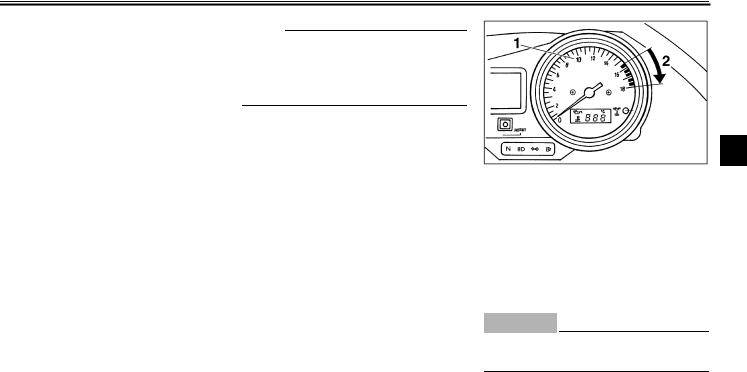
1.Tachometer
2.Red zone
EAU00101
Tachometer
This model is equipped with an electric tachometer so the rider can monitor the engine speed and keep it within the ideal power range.
EC000003
CAUTION:
@
Do not operate in the red zone. Red zone: 15,500 r/min and above
@
3-8
INSTRUMENT AND CONTROL FUNCTIONS
EAU00105
Diagnosis device
This model is equipped with a self diagnosis for the following circuits:
●Throttle Position Sensor (T.P.S.) circuit
●Fuel indicator light circuit
3
If some trouble should occur in any of these circuits, the tachometer will repeatedly display as follows:
0 r/min for |
Specified |
Current en- |
3 seconds |
r/min for the |
gine r/min for |
|
faulty circuit |
3 seconds |
|
for 2.5 sec- |
|
|
onds (see |
|
|
chart below) |
|
Use this chart to identify what circuit is faulty according to the specified r/min displayed.
Specified r/min |
Faulty circuit |
3,000 r/min
Throttle Position Sensor (T.P.S.)
8,000 r/min |
Fuel indicator light |
If the tachometer displays as described above, take note of the specified r/min and then take your motorcycle to a Yamaha dealer for repair.
EC000004
CAUTION:
To prevent engine damage, be sure to consult a Yamaha dealer as soon as possible if the tachometer displays a repeated change in r/min.
1.Pass switch “PASS”
2.Dimmer switch
3.Turn signal switch
4.Horn switch “ ”
”
EAU00118
Handlebar switches
EAU00120
Pass switch “PASS”
Press the switch to operate the passing light.
EAU00121
Dimmer switch
Turn the switch to “  ” for the high beam and to “
 ” for the low beam.
3-9
INSTRUMENT AND CONTROL FUNCTIONS
EAU00127
Turn signal switch
To signal a right-hand turn, push the switch to “ ”. To signal a left-hand turn, push the switch to “
 ”. Once the switch is released it will return to the center position. To cancel the signal, push the switch in after it has returned to the center position.
EAU00129
Horn switch “  ”
”
Press the switch to sound the horn.
1.Engine stop switch
2.Start switch “  ”
”
EAU00138
Engine stop switch
The engine stop switch is a safety device for use in an emergency such as when the motorcycle overturns or if trouble occurs in the throttle system. Turn the switch to “ ” to start the engine. In case of emergency, turn the switch to “
  ” to stop the engine.
EAU00143
Start switch “  ”
”
The starter motor cranks the engine when pushing the start switch.
EC000005
CAUTION:
@
See starting instructions prior to starting the engine.
|
3 |
@ |
3-10
Loading...