


YZF-R1V
YZF-R1VC YZF-R1LEV YZF-R1LEVC
SUPPLEMENTARY SERVICE MANUAL
LIT-11616-19-75 |
5VY-28197-11 |

FOREWORD
This Supplementary Service Manual has been prepared to introduce new service and data for the YZF-R1V/YZF-R1VC/YZF-R1LEV/YZF-R1LEVC. For complete service information procedures it is necessary to use this Supplementary Service Manual together with the following manual.
YZF-R1S/YZF-R1SC SERVICE MANUAL: LIT-11616-17-55 (5VY-28197-10)
EAS00001
YZF-R1V/YZF-R1VC
YZF-R1LEV/YZF-R1LEVC
SUPPLEMENTARY
SERVICE MANUAL ©2005 by Yamaha Motor Corporation, U.S.A.
First edition, October 2005
All rights reserved. Any reproduction or unauthorized use without the written permission of Yamaha Motor Corporation, U.S.A. is expressly prohibited.
Printed in U.S.A.
LIT-11616-19-75

EAS00030
NOTICE
This manual was produced by the Yamaha Motor Company, Ltd. primarily for use by Yamaha dealers and their qualified mechanics. It is not possible to include all the knowledge of a mechanic in one manual. Therefore, anyone who uses this book to perform maintenance and repairs on Yamaha vehicles should have a basic understanding of mechanics and the techniques to repair these types of vehicles. Repair and maintenance work attempted by anyone without this knowledge is likely to render the vehicle unsafe and unfit for use.
This model has been designed and manufactured to perform within certain specifications in regard to performance and emissions. Proper service with the correct tools is necessary to ensure that the vehicle will operate as designed. If there is any question about a service procedure, it is imperative that you contact a Yamaha dealer for any service information changes that apply to this model. This policy is intended to provide the customer with the most satisfaction from his vehicle and to conform to federal environmental quality objectives.
Yamaha Motor Company, Ltd. is continually striving to improve all of its models. Modifications and significant changes in specifications or procedures will be forwarded to all authorized Yamaha dealers and will appear in future editions of this manual where applicable.
NOTE:
•This Service Manual contains information regarding periodic maintenance to the emission control system. Please read this material carefully.
•Designs and specifications are subject to change without notice.
EAS00040
IMPORTANT MANUAL INFORMATION
Particularly important information is distinguished in this manual by the following.
|
|
The Safety Alert Symbol means ATTENTION! BECOME ALERT! YOUR |
||
|
|
SAFETY IS INVOLVED! |
||
WARNING |
Failure to follow WARNING instructions could result in severe injury or death |
|||
|
|
|||
to the vehicle operator, a bystander or a person checking or repairing the |
||||
|
|
|||
|
|
vehicle. |
||
|
|
A CAUTION indicates special precautions that must be taken to avoid dam- |
||
CAUTION: |
|
|||
|
age to the vehicle. |
|||
|
|
|||
NOTE: |
A NOTE provides key information to make procedures easier or clearer. |
|||

EAS00007
HOW TO USE THIS MANUAL
This manual is intended as a handy, easy-to-read reference book for the mechanic. Comprehensive explanations of all installation, removal, disassembly, assembly, repair and check procedures are laid out with the individual steps in sequential order.
 The manual is divided into chapters. An abbreviation and symbol in the upper right corner of each page indicate the current chapter.
Refer to “SYMBOLS”.
 Each chapter is divided into sections. The current section title is shown at the top of each page, except in Chapter 3 (“PERIODIC CHECKS AND ADJUSTMENTS”), where the sub-section title(s) appears.
 Sub-section titles appear in smaller print than the section title.
 To help identify parts and clarify procedure steps, there are exploded diagrams at the start of each removal and disassembly section.
 Numbers are given in the order of the jobs in the exploded diagram. A circled number indicates a disassembly step.
 Symbols indicate parts to be lubricated or replaced.
Refer to “SYMBOLS”.
 A job instruction chart accompanies the exploded diagram, providing the order of jobs, names of parts, notes in jobs, etc.
 Jobs requiring more information (such as special tools and technical data) are described sequentially.

EAS00008
SYMBOLS
The following symbols are not relevant to every vehicle.
Symbols  to
to  indicate the subject of each chapter.
 General information
 Specifications
 Periodic checks and adjustments
 Chassis
 Engine
 Cooling system
 Fuel injection system
 Electrical system
  Troubleshooting
Symbols  to
to  indicate the following.
 Serviceable with engine mounted
 Filling fluid
 Lubricant
 Special tool
 Tightening torque
 Wear limit, clearance
 Engine speed
  Electrical data
Symbols  to
to  in the exploded diagrams indicate the types of lubricants and lubrication points.
 Engine oil
 Gear oil
 Molybdenum-disulfide oil
 Wheel-bearing grease
 Lithium-soap-based grease
 Molybdenum-disulfide grease
Symbols  to
to  in the exploded diagrams indicate the following.
 Apply locking agent (LOCTITE®)
  Replace the part with a new one.

CONTENTS |
|
GENERAL INFORMATION |
|
SPECIAL TOOLS. . . . . . . . . . . . . . . . . . . . . . . . . . . . . . . . . . . . . . . . . |
1 |
SPECIFICATIONS |
|
GENERAL SPECIFICATIONS . . . . . . . . . . . . . . . . . . . . . . . . . . . . . . . |
2 |
ENGINE SPECIFICATIONS. . . . . . . . . . . . . . . . . . . . . . . . . . . . . . . . . |
3 |
CHASSIS SPECIFICATIONS. . . . . . . . . . . . . . . . . . . . . . . . . . . . . . . . |
4 |
ELECTRICAL SPECIFICATIONS . . . . . . . . . . . . . . . . . . . . . . . . . . . . |
7 |
TIGHTENING TORQUES. . . . . . . . . . . . . . . . . . . . . . . . . . . . . . . . . . . |
7 |
ENGINE TIGHTENING TORQUES . . . . . . . . . . . . . . . . . . . . . . . . |
7 |
CHASSIS TIGHTENING TORQUES . . . . . . . . . . . . . . . . . . . . . . . |
8 |
LUBRICATION POINTS AND LUBRICANT TYPES . . . . . . . . . . . . . . |
9 |
ENGINE . . . . . . . . . . . . . . . . . . . . . . . . . . . . . . . . . . . . . . . . . . . . . |
9 |
CHASSIS . . . . . . . . . . . . . . . . . . . . . . . . . . . . . . . . . . . . . . . . . . . . |
9 |
LUBRICATION DIAGRAMS . . . . . . . . . . . . . . . . . . . . . . . . . . . . . . . . |
10 |
CABLE ROUTING . . . . . . . . . . . . . . . . . . . . . . . . . . . . . . . . . . . . . . . . |
11 |
PERIODIC CHECKS AND ADJUSTMENTS |
|
INTRODUCTION . . . . . . . . . . . . . . . . . . . . . . . . . . . . . . . . . . . . . . . . . |
27 |
PERIODIC MAINTENANCE CHART FOR THE EMISSION |
|
CONTROL SYSTEM . . . . . . . . . . . . . . . . . . . . . . . . . . . . . . . . . . . . . . |
27 |
GENERAL MAINTENANCE AND LUBRICATION CHART . . . . . . . . |
27 |
CHASSIS . . . . . . . . . . . . . . . . . . . . . . . . . . . . . . . . . . . . . . . . . . . . . . . |
29 |
ADJUSTING THE FRONT FORK LEGS. . . . . . . . . . . . . . . . . . . . . |
29 |
ADJUSTING THE REAR SHOCK ABSORBER ASSEMBLY . . . . . |
32 |
CHASSIS |
|
FRONT WHEEL AND BRAKE DISCS. . . . . . . . . . . . . . . . . . . . . . . . . |
35 |
REAR WHEEL AND BRAKE DISCS . . . . . . . . . . . . . . . . . . . . . . . . . . |
36 |
REAR BRAKE DISC AND REAR WHEEL SPROCKET . . . . . . . . . |
36 |
FRONT FORK . . . . . . . . . . . . . . . . . . . . . . . . . . . . . . . . . . . . . . . . . . . |
38 |
FRONT FORK LEGS . . . . . . . . . . . . . . . . . . . . . . . . . . . . . . . . . . . |
38 |
DISASSEMBLING THE FRONT FORK LEGS . . . . . . . . . . . . . . . . |
40 |
CHECKING THE FRONT FORK LEGS . . . . . . . . . . . . . . . . . . . . . |
42 |
ASSEMBLING THE FRONT FORK LEGS . . . . . . . . . . . . . . . . . . . |
43 |
REAR SHOCK ABSORBER ASSEMBLY . . . . . . . . . . . . . . . . . . . . . . |
47 |
REMOVING THE REAR SHOCK ABSORBER ASSEMBLY . . . . . 49 |
|
INSTALLING THE REAR SHOCK ABSORBER ASSEMBLY. . . . . |
50 |
SWINGARM AND DRIVE CHAIN . . . . . . . . . . . . . . . . . . . . . . . . . . . . |
51 |
REMOVING THE SWINGARM . . . . . . . . . . . . . . . . . . . . . . . . . . . . |
51 |
CHECKING THE SWINGARM . . . . . . . . . . . . . . . . . . . . . . . . . . . . |
52 |
CHECKING THE CONNECTING ROD ASSEMBLY . . . . . . . . . . . |
53 |
CHECKING THE DRIVE CHAIN. . . . . . . . . . . . . . . . . . . . . . . . . . . |
54 |

ENGINE
ENGINE . . . . . . . . . . . . . . . . . . . . . . . . . . . . . . . . . . . . . . . . . . . . . 56 INSTALLING THE ENGINE . . . . . . . . . . . . . . . . . . . . . . . . . . . . . . 58 CAMSHAFTS . . . . . . . . . . . . . . . . . . . . . . . . . . . . . . . . . . . . . . . . . 60 CLUTCH . . . . . . . . . . . . . . . . . . . . . . . . . . . . . . . . . . . . . . . . . . . . . . . . 61 CLUTCH COVER . . . . . . . . . . . . . . . . . . . . . . . . . . . . . . . . . . . . . . 61 CLUTCH . . . . . . . . . . . . . . . . . . . . . . . . . . . . . . . . . . . . . . . . . . . . . 62 REMOVING THE CLUTCH. . . . . . . . . . . . . . . . . . . . . . . . . . . . . . . 66 CHECKING THE FRICTION PLATES . . . . . . . . . . . . . . . . . . . . . . 67 CHECKING THE CLUTCH PLATES. . . . . . . . . . . . . . . . . . . . . . . . 68 CHECKING THE CLUTCH SPRINGS . . . . . . . . . . . . . . . . . . . . . . 69 CHECKING THE CLUTCH HOUSING . . . . . . . . . . . . . . . . . . . . . . 69 CHECKING THE PRESSUR PLATE 2 . . . . . . . . . . . . . . . . . . . . . . 70 CHECKING THE CLUTCH BOSS . . . . . . . . . . . . . . . . . . . . . . . . . 70 CHECKING THE PRESSURE PLATE 1. . . . . . . . . . . . . . . . . . . . . 70 CHECKING THE PULL LEVER SHAFT AND PULL ROD . . . . . . . 71 INSTALLING THE CLUTCH . . . . . . . . . . . . . . . . . . . . . . . . . . . . . . 71
YZF-R1V/YZF-R1VC/YZF-R1LEV/YZF-R1LEVC 2006 WIRING DIAGRAM
SPECIAL TOOLS
EAS00027
GEN INFO
GENERAL INFORMATION
SPECIAL TOOLS
The following special tools are necessary for complete and accurate tune-up and assembly. Use only the appropriate special tools as this will help prevent damage caused by the use of inappropriate tools or improvised techniques. Special tools, part numbers or both may differ depending on the country.
When placing an order, refer to the list provided below to avoid any mistakes.
NOTE:
•For U.S.A. and Canada, use part number starting with “YM-”, “YU-”, or “ACC-”.
•For others, use part number starting with “90890-”.
(YZF-R1LE)
Tool No. |
Tool name/Function |
Illustration |
|
Front fork cap bolt wrench |
|
90890-01472 |
|
|
|
This tool is used to loosen or tighten the front |
|
|
fork cap bolt. |
|
|
Damper rod holder |
|
90890-01504 |
|
|
|
This tool is used to loosening or tightening |
|
|
the damper rod assembly. |
|
Rod puller |
Rod puller |
|
90890-01437 |
Rod puller attachment |
|
YM-A8703 |
|
|
|
|
|
Rod puller |
|
|
attachment |
These tools are used to pull up the front fork |
|
90890-01435 |
damper rod. |
|
YM-A8703 |
|
1

GENERAL SPECIFICATIONS |
|
SPEC |
|
|
|
|
|
|
|
|
|
SPECIFICATIONS |
|
|
|
GENERAL SPECIFICATIONS |
|
|
|
Item |
Standard |
Limit |
|
|
|
Model code |
YZF-R1 |
|
|
5VYH (USA), 5VYL (USA) |
••• |
|
5VYJ (CAL), 5VYM (CAL) |
|
|
YZF-R1LE |
|
|
4B14 (USA), 4B15 (CAL) |
••• |
Dimensions |
|
|
Overall length |
2,085 mm (82.1 in) |
••• |
Wheelbase |
1,415 mm (55.7 in) |
••• |
Weight |
|
|
Wet (with oil and a full fuel tank) |
194 kg (428 lb) (USA) (YZF-R1) |
••• |
|
195 kg (430 lb) (CAL) (YZF-R1) |
••• |
|
195 kg (430 lb) (USA) (YZF-R1LE) |
••• |
|
195 kg (430 lb) (CAL) (YZF-R1LE) |
••• |
Maximum load (except vehicle) |
201 kg (443 lb) (USA) (YZF-R1) |
••• |
|
200 kg (441 lb) (CAL) (YZF-R1) |
••• |
|
200 kg (441 lb) (USA) (YZF-R1LE) |
••• |
|
200 kg (441 lb) (CAL) (YZF-R1LE) |
••• |
|
|
|
2
ENGINE SPECIFICATIONS |
|
SPEC |
|
|
|
|
|
|
|
|
|
ENGINE SPECIFICATIONS |
|
|
|
Item |
Standard |
Limit |
|
|
|
Oil pump |
|
|
Oil-pump-housing-to-inner-and-outer- |
0.06 ~ 0.13 mm |
0.20 mm |
rotor clearance |
(0.0024 ~ 0.0051 in) |
(0.0079 in) |
|
|
|
Cylinder head |
12.3 ~ 12.9 cm3 (0.75 ~ 0.79 cu.in) |
|
Volume |
••• |
|
Max. warpage |
••• |
0.10 mm |
|
|
(0.0039 in) |
|
|
|
Piston |
|
|
Diameter D |
76.975 ~ 76.990 mm (3.0305 ~ 3.0311 in) |
••• |
Height H |
12 mm (0.47 in) |
••• |
|
|
|
Clutch |
|
|
Friction plates |
|
|
Color code |
Red |
••• |
Thickness |
2.9 ~ 3.1 mm (0.114 ~ 0.122 in) |
2.8 mm |
|
|
(0.110 in) |
Plate quantity |
7 |
••• |
Color code |
Red |
••• |
Thickness |
2.9 ~ 3.1 mm (0.114~ 0.122 in) |
2.8 mm |
|
|
(0.110 in) |
Plate quantity |
1 |
••• |
Color code |
Red |
••• |
Thickness |
2.9 ~ 3.1 mm (0.114 ~ 0.122 in) |
2.8 mm |
|
|
(0.110 in) |
Plate quantity |
1 |
••• |
Clutch plates |
|
|
Thickness |
1.9 ~ 2.1 mm (0.07 ~ 0.08 in) |
••• |
Plate quantity |
8 |
••• |
Max. warpage |
••• |
0.1 mm |
|
|
(0.0039 in) |
Clutch springs |
|
|
Free length |
43.8 mm (1.72 in) (YZF-R1LE) |
41.6 mm |
|
|
(1.64 in) |
|
|
|
Throttle bodies |
|
|
ID mark |
5VY1 30 (USA), 5VY1 40 (CAL) |
••• |
|
|
|
3

CHASSIS SPECIFICATIONS |
|
SPEC |
|
|
|
|
|
|
|
|
|
CHASSIS SPECIFICATIONS |
|
|
|
Item |
Standard |
Limit |
|
|
|
Front wheel |
|
|
Wheel type |
Forged wheel (YZF-R1LE) |
••• |
|
|
|
Rear wheel |
|
|
Wheel type |
Forged wheel (YZF-R1LE) |
••• |
|
|
|
Front tire |
|
|
Model (manufacturer) |
Pilot POWER (MICHELIN) (YZF-R1) |
••• |
|
D218FG (DUNLOP) (YZF-R1) |
••• |
|
DIABLO CORSA H (PIRELLI) (YZF-R1LE) |
••• |
Tire pressure (cold) |
250 kPa (2.5 kgf/cm2, 2.5 bar, 35.6 psi) |
|
90 ~ 201 kg (198 ~ 443 lb) |
••• |
|
|
(USA) (YZF-R1) |
|
90 ~ 200 kg (198 ~ 441 lb) |
250 kPa (2.5 kgf/cm2, 2.5 bar, 35.6 psi) |
••• |
|
(CAL) (YZF-R1) |
|
90 ~ 200 kg (198 ~ 441 lb) |
250 kPa (2.5 kgf/cm2, 2.5 bar, 35.6 psi) |
••• |
|
(USA) (YZF-R1LE) |
|
90 ~ 200 kg (198 ~ 441 lb) |
250 kPa (2.5 kgf/cm2, 2.5 bar, 35.6 psi) |
••• |
|
(CAL) (YZF-R1LE) |
|
|
|
|
Rear tire |
|
|
Model (manufacturer) |
Pilot POWER/Pilot POWER G |
••• |
|
(MICHELIN) (YZF-R1) |
|
|
D218G (DUNLOP) (YZF-R1) |
••• |
|
DIABLO CORSA (PIRELLI) (YZF-R1LE) |
••• |
Tire pressure (cold) |
290 kPa (2.9 kgf/cm2, 2.9 bar, 41.3 psi) |
|
90 ~ 201 kg (198 ~ 443 lb) |
••• |
|
|
(USA) (YZF-R1) |
|
90 ~ 200 kg (198 ~ 441 lb) |
290 kPa (2.9 kgf/cm2, 2.9 bar, 41.3 psi) |
••• |
|
(CAL) (YZF-R1) |
|
90 ~ 200 kg (198 ~ 441 lb) |
290 kPa (2.9 kgf/cm2, 2.9 bar, 41.3 psi) |
••• |
|
(USA) (YZF-R1LE) |
|
90 ~ 200 kg (198 ~ 441 lb) |
290 kPa (2.9 kgf/cm2, 2.9 bar, 41.3 psi) |
••• |
|
(CAL) (YZF-R1LE) |
|
|
|
|
4

CHASSIS SPECIFICATIONS |
|
SPEC |
|
|
|
|
|
|
|
|
|
Item |
Standard |
Limit |
|
|
|
Front brakes |
|
|
Master cylinder inside diameter |
16 mm (0.63 in) |
••• |
Caliper cylinder inside diameter |
30.2 mm and 27 mm (1.19 in and 1.06 in) |
••• |
|
|
|
Front suspension |
|
|
(YZF-R1) |
|
|
Fork oil |
|
|
Quantity (each front fork leg) |
0.52 L (0.46 Imp qt, 0.55 US qt) |
••• |
Level (from the top of the outer tube, |
90 mm (3.54 in) |
••• |
with the outer tube fully compressed, |
|
|
and without the fork spring) |
|
|
Spring preload adjusting positions |
|
|
Minimum |
8 |
••• |
Standard |
4.5 |
••• |
Maximum |
0 |
••• |
(YZF-R1LE) |
|
|
Spring |
|
|
Free length |
260 mm (10.24 in) |
254.8 mm |
|
|
(10.03 in) |
Coller length |
42 mm (1.653 in) |
••• |
Installed length |
248.0 mm (9.76 in) |
••• |
Spring rate (K1) |
9.50 N/mm (0.97 kg/mm, 54.22 lb/in) |
••• |
Fork oil |
|
|
Recommended oil |
Suspension oil “Ohlins R&T 43” |
••• |
|
(ACC-RT43F-00-00) |
|
Quantity (each front fork leg) |
0.43 L (0.38 Imp qt, 0.45 US qt) |
••• |
Level (from the top of the outer tube, |
145 mm (5.71 in) |
••• |
with the outer tube fully compressed, |
|
|
and without the fork spring) |
|
|
Spring preload adjusting positions |
|
|
Minimum* |
11 turns out* |
••• |
Maximum* |
2 turns in* |
••• |
*from the standard position |
|
|
Rebound damping adjusting positions |
|
|
Minimum** |
17 |
••• |
Standard** |
12 |
••• |
Maximum** |
1 |
••• |
Compression damping adjusting |
|
|
positions |
|
|
Minimum** |
20 |
••• |
Standard** |
12 |
••• |
Maximum** |
1 |
••• |
**from the fully turned-in direction |
|
|
|
|
|
5

CHASSIS SPECIFICATIONS |
|
SPEC |
|
|
|
|
|
|
|
|
|
Item |
Standard |
Limit |
|
|
|
Rear suspension |
|
|
(YZF-R1) |
|
|
Spring preload adjusting positions |
|
|
Minimum |
1 |
••• |
Standard |
5 |
••• |
Maximum |
9 |
••• |
(YZF-R1LE) |
|
|
Spring |
|
|
Free length |
150.0 mm (5.91 in) |
••• |
Installed length |
139.0 mm (5.47 in) |
••• |
Spring rate (K1) |
95.0 N/mm (9.68 kg/mm, 542.18 lb/in) |
••• |
Spring preload adjusting positions |
|
|
Minimum* |
0 |
••• |
Standard* |
6 |
••• |
Maximum* |
20 |
••• |
Rebound damping adjusting positions |
|
|
Minimum* |
18 |
••• |
Standard* |
14 |
••• |
Maximum* |
1 |
••• |
Compression damping adjusting |
|
|
positions (fast compression damping) |
|
|
Minimum* |
42 |
••• |
Standard* |
30 |
••• |
Maximum* |
1 |
••• |
Compression damping adjusting |
|
|
positions (slow compression damping) |
|
|
Minimum* |
17 |
••• |
Standard* |
10 |
••• |
Maximum* |
1 |
••• |
*from the fully turned-in position |
|
|
|
|
|
Drive chain |
|
|
Model (manufacturer) |
50VA8 (DAIDO) |
••• |
Link quantity |
118 |
••• |
Drive chain slack |
20 ~ 25 mm (0.79 ~ 0.98 in) |
••• |
Maximum 15-link section |
••• |
239.3 mm |
|
|
(9.42 in) |
|
|
|
6

ELECTRICAL SPECIFICATIONS/TIGHTENING TORQUES |
|
SPEC |
|
|
|
|
|
|
|
|
|
ELECTRICAL SPECIFICATIONS |
|
|
|
Item |
Standard |
Limit |
|
|
|
Ignition system |
|
|
T.C.I. unit model (manufacturer) |
F8T82075 (MITSUBISHI) |
••• |
|
|
|
Battery |
|
|
Manufacturer |
GS-YUASA |
••• |
Ten hour rate amperage |
0.9 A |
••• |
|
|
|
TIGHTENING TORQUES
ENGINE TIGHTENING TORQUES
Item |
Fastener |
Thread |
Q’ty |
Tightening torque |
Remarks |
|||
|
|
|
||||||
size |
Nm |
m•kg |
ft•lb |
|||||
|
|
|
|
|||||
|
|
|
|
|
|
|
|
|
Exhaust pipe and exhaust valve pipe |
Bolt |
M6 |
5 |
12 |
1.2 |
8.7 |
|
|
assembly |
|
|
|
|
|
|
|
|
EXUP servo motor |
Bolt |
M6 |
2 |
6 |
0.6 |
4.3 |
|
|
Crankcase |
Bolt |
M6 |
10 |
10 |
1.0 |
7.2 |
|
|
Drive sprocket cover |
Bolt |
M6 |
2 |
12 |
1.2 |
8.7 |
|
|
Drive sprocket cover |
Bolt |
M6 |
1 |
12 |
1.2 |
8.7 |
|
|
Plate |
Bolt |
M6 |
2 |
12 |
1.2 |
8.7 |
|
|
|
|
|
|
|
|
|
|
|
7

TIGHTENING TORQUES |
|
SPEC |
|
|
|
|
|
|
|
|
|
CHASSIS TIGHTENING TORQUES |
|
|
|
Item |
Thread |
Tightening |
Remarks |
|||
size |
Nm |
m•kg |
ft•lb |
|||
|
|
|||||
|
|
|
|
|
|
|
Horn bracket and under bracket |
M6 |
7 |
0.7 |
5.1 |
|
|
Connecting rod assembly (YZF-R1LE) |
M6 |
8 |
0.8 |
5.8 |
|
|
Side cover and fuel tank |
M5 |
4 |
0.4 |
2.9 |
|
|
Front fork and stay (YZF-R1LE) |
M5 |
6 |
0.6 |
4.3 |
|
|
Front fork and bracket (YZF-R1LE) |
M5 |
6 |
0.6 |
4.3 |
|
|
Rear brake master cylinder and foot rest bracket |
M6 |
13 |
1.3 |
9.4 |
|
|
Front brake disc and front wheel (YZF-R1LE) |
M6 |
23 |
2.3 |
17 |
|
|
Front wheel axle pinch bolt (YZF-R1LE) |
M8 |
26 |
2.6 |
19 |
See NOTE |
|
Cap bolt (YZF-R1LE) |
– |
20 |
2.0 |
14 |
|
|
Cap bolt and lock nut (YZF-R1LE) |
M12 |
25 |
2.5 |
18 |
|
|
Damper rod assembly (YZF-R1LE) |
– |
48 |
4.8 |
35 |
|
|
|
|
|
|
|
|
|
NOTE:
1. Insert the front wheel axle from the right side and tighten it with the flange bolt from the left side to 91 Nm (9.1 m•kg, 65.8 ft•lb).
2. In the order from the pinch bolt  → pinch bolt
  → pinch bolt
  , tighten each bolt to 26 Nm (2.6 m•kg, 19 ft•lb) without performing temporary tightening.
3. Check that the end face of the axle head and the end face of the fork side are flushmounted. If they are out of alignment, make sure to fit them by adding the external force by hand or with a plastic hammer, etc.
If the end face of the axle is not parallel to the end face of the fork, align them so that one point of the axle circumference is positioned on the end face of the fork.
At this stage, it can be accepted if the end face of the axle becomes partially concave to the end face of the fork.
4. In the order from the pinch bolt  → pinch bolt
  → pinch bolt
  , tighten each bolt to 26 Nm (2.6 m•kg, 19 ft•lb) without performing temporary tightening.
8

LUBRICATION POINTS AND LUBRICANT TYPES |
|
SPEC |
|
|
|
|
|
|
|
|
|
EAS00031 |
|
|
|
LUBRICATION POINTS AND LUBRICANT TYPES |
|
|
|
ENGINE |
|
|
|
Lubrication point |
Lubricant |
|
|
Valve lifter surfaces (intake and exhaust) |
|
|
|
Valve stem ends (intake and exhaust) |
|
|
|
EAS00032 |
|
CHASSIS |
|
|
|
Lubrication point |
Lubricant |
|
|
Pivot shaft |
|
|
|
9
LUBRICATION DIAGRAMS |
|
SPEC |
|
|
|
|
|
|
|
|
|
LUBRICATION DIAGRAMS
Main axle
Oil delivery pipe
Drive axle
10

CABLE ROUTING |
|
SPEC |
|
|
|
|
|
|
|
|
|
EAS00035
CABLE ROUTING
Ground lead |
Insert to the rib of the head |
Meter lead |
light. (Either location of the right |
Stay 1 |
and left relays is acceptable.) |
Auxiliary light lead (right) |
The lead should not stretch too |
Headlight lead |
much. |
Auxiliary light lead (left) |
Direction of the ground terminal |
Console panel 1 |
can be either top side or flip |
Duct 1 |
side. |
Console panel 2 |
Make sure to insert the coupler |
Duct 2 |
and boot to the stay 1 hole. |
Headlight lead (right) |
The speedometer lead should |
Headlight lead (left) |
not be strained. |
|
To the stay 1 hole |
 Connect after passing over the upper side of the duct.
 Clamp the head light lead by wrapping and insert it to the intake air grill hole. (only at the right side.)
 Do not connect the wire to the coupler with the plug for options.
 To the turn signal light
 To the wire harness
 Cut the tip of the clamp.
Clamp the headlight lead to the positioning white tape section.
11

CABLE ROUTING |
|
SPEC |
|
|
|
|
|
|
|
|
|
 There should be no slack when clamping. Point the tip of the clamp (excessive part) to the front side of the vehicle. Fasten the head light lead with a clamp.
  Feed a lead wire through the U shape cutout of the console panel.
12
CABLE ROUTING |
|
SPEC |
|
|
|
|
|
|
|
|
|
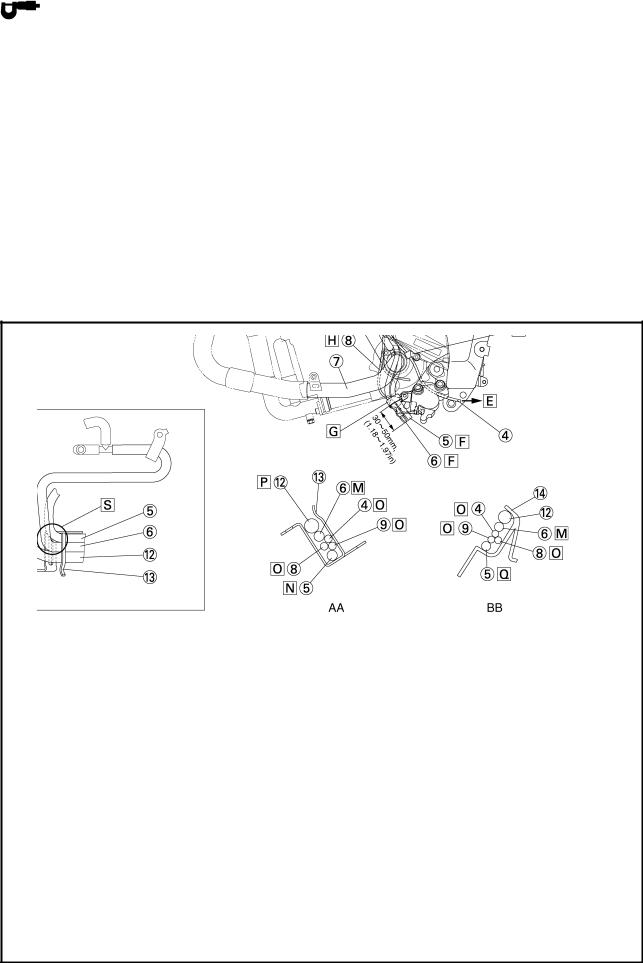
Right handlebar switch lead |
Route the clutch cable so as to |
Clutch cable |
get along the front side of the |
Main switch lead |
main switch after passing it |
Left handlebar switch lead |
through the guide. |
Horn lead |
Pass the main switch lead |
Horn |
through the guide wire. |
Throttle cables |
Pass the left handlebar switch |
Brake hose |
lead through the guide wire. |
Throttle cable (return side) |
Point the tip of the band (exces- |
Throttle cable (pull side) |
sive part) to the left side of the |
|
vehicle and cut the surplus sec- |
|
tion. |
|
Clamp the section between 0 |
|
and 20 mm (0 and 0.79 in) from |
|
the split of the under bracket. |
 Clamp the leads inside the front fork of the vehicle. Point the exit of the horn lead to the left front fork side.
 Route two throttle cables behind the brake hose, pass between the inside of the under bracket’s upper side front fork and guide wire assembly, and then pass it through the clamp that is inserted to the cover 3 under the frame.
13

CABLE ROUTING |
|
SPEC |
|
|
|
|
|
|
|
|
|
 Contact the wire guide to the top face of the under bracket boss. The throttle cable should not be caught between the wire guide and under bracket. The throttle cable (pull side) should be positioned above the vehicle wen the wire guide is installed.
 Clamp should be positioned at the protector lower end of the brake hose and wrapped on the protector.
 Cut the tip leaving 2 to 4mm 0.08 ~ 0.16 in).
14

CABLE ROUTING |
SPEC |
|
|
|
|
||
|
|
|
|
Wire harness |
Throttle body lead |
|
Crankshaft position sensor lead |
|
|
Heat protector |
Clamp it after passing between |
|
Right handlebar switch lead |
the frame and radiator stay. |
|
Positioning guide |
Point the tip of the clamp |
|
Rear brake light switch lead |
(excessive part) to the front side |
|
Coolant reservoir tank |
of the vehicle. Fasten the right |
|
Speed sensor lead |
handlebar switch lead with a |
|
Clutch cable |
clamp. |
|
Radiator |
To the wire harness |
|
Oil cooler outlet hose |
The clutch cable positioning |
|
Coolant reservoir tank drain |
guide should be above the |
|
hose |
upper end of the clamp. Fasten |
|
Breather pipe |
the clutch cable with a clamp. |
|
Fuel tank drain hose |
(Refer to |
) |
A.C. magneto lead |
Position |
relation between the |
Wire harness |
clamp and guide. |
|
 Clamp the clamp upper end along the line of lower end of the hose clamp assembly. Point the tip of the clamp (excessive part) to the front side of the vehicle. Clutch cable is what the clamp fastens.
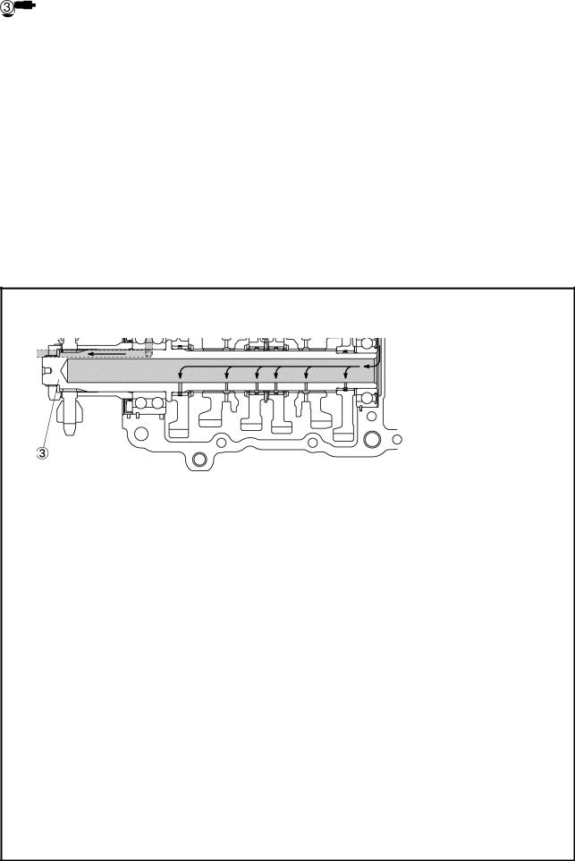
 The clutch cable doesn’t project outside the water hose and the cylinder head in the box part in the figure.
 To the engine
 Clamp behind the bracket 3. Cut the tip of the clamp.
for CAL
15

CABLE ROUTING |
|
SPEC |
|
|
|
|
|
|
|
|
|
 The coupler for the air induction solenoid lead and camshaft sensor lead should be connected above the ignition coil sub wire harness and it should not drop on the cylinder head cover behind the ignition coil.
 Pass the right handlebar switch lead between the frame and heat protector.
 Coolant reservoir tank drain hose should cross with the speed sensor lead under the swingarm bracket. Route the coolant reservoir tank drain hose over the up side of the vehicle.
 Pass the rear brake light switch lead between the swingarm bracket and coolant reservoir tank.
 Release the tip of the clamp and install it to the clutch cable. Insert the clamp to the hole located on the right back side of the radiator.
Radiator fan motor lead should not be caught while inserting the clamp.
 Push the clamp until it hits the radiator side stay. Radiator fan motor lead should not be caught.
 Clamp the clutch cable so that it is within this specified clamp.
 To the air filter
 Route the fuel tank drain hose over the canister stay and between the breather hose 2 and wire harness. On the front side of the canister stay, let though the bottom of the A.C.magneto lead and the wire harness.
 Route by the upside of vehicle away from the canister stay.
for CAL
16

CABLE ROUTING |
|
SPEC |
|
|
|
|
|
|
|
|
|
Heat protector Main switch lead
Left handlebar switch lead EXUP servo motor lead Coolant reservoir tank drain hose Fuel tank drain hose
Coolant outlet pipe Sidestand switch lead Oil level switch lead A.C.magneto lead Fuse box stay
Water hose Stay 1
Chain case cover
 Clamp the leads so that they are positioned inner of the vehicle than the washer position after routing them between the frame and radiator stay. Align the clamp position with the taping sections of leads. Point the tip of the clamp (excessive part) to the down front side of the vehicle. What the clamp fastens at this stage are the handlebar switch and main switch leads.
 Pass the main switch lead and left handlebar switch lead between the frame and the heat protector.
 To the coolant reservoir tank
 Fold back the clamp and secure it after passing the lead through the clamp.
 To the EXUP servo motor
 Pass the coolant reservoir tank drain hose and fuel tank drain hose through the clamp from the outer side of the water pump inlet pipe after routing it behind the water pump breather hose. The lengths of two hose ends are allowed to be random. Any direction of cut edges can be accepted. (Only for the fuel tank drain hose)
17
CABLE ROUTING |
|
SPEC |
|
|
|
|
|
|
|
|
|
 Clamp the fuel tank drain hose and fuel tank breather hose.
 Route the lead by the inside of the water hose and water pipe.
 Route the lead by the inside of the water hose and water pipe.
 There should be no exposure of bared conductors due to the displacement of the tube.
 Route by the outside of vehicle away from the water hose.
 Point the tip of the clamp (excessive part) to the down rear side of the vehicle. Fasten the wire harness with a clamp.
 The outside of the vehicle.
 Inner most section of the vehicle.
 Can be routed in any order.
 Route the water hose so that it is placed at the outermost position finally after routing other leads and hoses in the guide.
 Route the coolant reservoir tank drain hose so that it is routed at the innermost position to each hose and lead.
 Arrange so as not for each hose to cross in the part between “BB” from the section “AA” which is in the illustration.
 Align the molded part of the fuel tank drain hose with the stay 1.
 Routing of the fuel tank drain hose.
EXUP servo motor, oil level switch and sidestand switch leads are omitted in this drawing.
18
|
CABLE ROUTING |
|
SPEC |
|
|
|
|
|
|
||
|
|
|
|
|
|
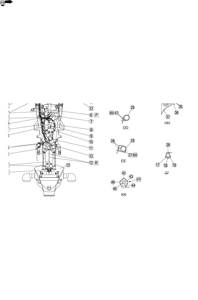
Heat protector |
Battery negative lead |
Throttle body side cap |
|||
Crankshaft position sensor lead |
Starter motor lead |
Mud guard |
|||
Neutral switch lead |
A.C.magneto lead |
Turn signal light lead |
|||
Ground lead |
Oil level switch lead |
License plate light lead |
|||
Coolant reservoir tank |
Sidestand switch lead |
Rear fender rib |
|||
Battery positive lead |
Throttle body lead |
Speed sensor lead |
|||
Starter relay |
Coolant reservoir tank drain hose |
Rear brake light switch lead |
|||
Turn signal relay |
Fuel tank drain hose |
Rear frame |
|||
Main fuse |
Cover 7 |
Swingarm bracket |
|||
Lean angle sensor |
Radiator fan motor lead (left) |
Main fuse lead |
|||
Atmospheric pressure sensor |
Radiator fan motor lead (right) |
Starting circuit cut-off relay lead |
|||
Tail /brake light lead |
Wire harness |
Turn signal light relay lead |
|||
Rear fender |
Pipe 3 |
Starter relay lead |
|||
Seat lock cable |
Frame |
Main fuse lead (To the battery |
|||
Anti safety alarm coupler |
Coolant reservoir tank hose |
positive lead) |
|||
Starting circuit cut-off relay |
Thermo stat assembly breather |
Right handlebar switch lead |
|||
|
hose |
|
|
|
|
|
|
|
|
|
|
|
|
|
|
|
|
19
 Loading...