


YZ250 AA1 2011
Table of contents
 Loading...
2011
q Read this manual carefully before operating this vehicle.
q Il convient de lire attentivement ce manuel avant la première utilisation du véhicule.
q
Bitte lesen Sie diese Bedienungsanleitung sorgfältig durch, bevor Sie das Fahrzeug in Betrieb nehmen.
q Leggere attentamente questo manuale prima di utilizzare questo veicolo.
OWNER’S SERVICE MANUAL
MANUEL D’ATELIER DU
PROPRIETAIRE
FAHRER- UND
WARTUNGSHANDBUCH
MANUALE DI SERVIZIO DEL
PROPRIETARI
O
YZ250(A)/A1
1P8-28199-36

Q
Read this manual carefully before operating this vehicle. This manual should stay with this vehicle if it is sold.
Q
Il convient de lire attentivement ce manuel avant la première utilisation du véhicule. Le manuel doit
être remis avec le véhicule en cas de vente de ce dernier.
Q
Bitte lesen Sie diese Bedienungsanleitung sorgfältig durch, bevor Sie das Fahrzeug in Betrieb nehmen.
Diese Bedienungsanleitung muss, wenn das Fahrzeug verkauft wird, beim Fahrzeug verbleiben.
Q
Leggere attentamente questo manuale prima di utilizzare il veicolo. Questo manuale dovrebbe
accompagnare il veicolo se viene venduto.

Read this manual carefully before operating this vehicle.Read this manual carefully before operating this vehicle.
20112011
OWNER’S SERVICE MANUALOWNER’S SERVICE MANUAL
YZ250(A)/A1YZ250(A)/A1
1P8-28199-36-E01P8-28199-36-E0


YZ250 (A)/A1
OWNER'S SERVICE MANUAL
©2010 by Yamaha Motor Co., Ltd.
1st Edition, June 2010
All rights reserved. Any reprinting or
unauthorized use without the written
permission of Yamaha Motor Co., Ltd.
is expressly prohibited.
Printed in Japan
FOREWORD
INTRODUCTION
Congratulations on your purchase of
a Yamaha YZ series. This model is
the culmination of Yamaha's vast experience in the production of pacesetting racing machines. It represents
the highest grade of craftsmanship
and reliability that have made Yamaha a leader.
This manual explains operation, inspection, basic maintenance and tuning of your machine. If you have any
questions about this manual or your
machine, please contact your Yamaha dealer.
Yamaha continually seeks advancements in product design and quality.
Therefore, while this manual contains
the most current product information
available at the time of printing, there
may be minor discrepancies between
your machine and this manual. If you
have any questions concerning this
manual, please consult your Yamaha
dealer.
PLEASE READ THIS MANUAL
CAREFULLY AND COMPLETELY
BEFORE OPERATING THIS MACHINE. DO NOT ATTEMPT TO OPERATE THIS MACHINE UNTIL YOU
HAVE ATTAINED A SATISFACTORY KNOWLEDGE OF ITS CONTROLS AND OPERATING
FEATURES AND UNTIL YOU HAVE
BEEN TRAINED IN SAFE AND
PROPER RIDING TECHNIQUES.
REGULAR INSPECTIONS AND
CAREFUL MAINTENANCE,
ALONG WITH GOOD RIDING
SKILLS, WILL ENSURE THAT YOU
SAFETY ENJOY THE CAPABILITIES AND THE RELIABILITY OF
THIS MACHINE.
IMPORTANT MANUAL
INFORMATION
Particularly important information is
distinguished in this manual by the
following notations.
This is the safety alert symbol. It is
used to alert you to potential personal injury hazards. Obey all safety messages that follow this
symbol to avoid possible injury or
death.
A WARNING indicates a hazardous
situation which, if not avoided,
could result in death or serious injury.
A NOTICE indicates special precautions that must be taken to
avoid damage to the vehicle or other property.
A TIP provides key information to
make procedures easier or clearer.
SAFETY INFORMATION
THIS MACHINE IS DESIGNED
STRICTLY FOR COMPETITION
USE, ONLY ON A CLOSED
COURSE. It is illegal for this machine
to be operated on any public street,
road, or highway. Off-road use on
public lands may also be illegal.
Please check local regulations before
riding.
• THIS MACHINE IS TO BE OPERATED BY AN EXPERIENCED RIDER ONLY.
Do not attempt to operate this machine at maximum power until you
are totally familiar with its characteristics.
• THIS MACHINE IS DESIGNED TO
BE RIDDEN BY THE OPERATOR
ONLY.
Do not carry passengers on this
machine.
• ALWAYS WEAR PROTECTIVE
APPAREL.
When operating this machine, always wear an approved helmet with
goggles or a face shield. Also wear
heavy boots, gloves, and protective
clothing. Always wear proper fitting
clothing that will not be caught in
any of the moving parts or controls
of the machine.
• ALWAYS MAINTAIN YOUR MACHINE IN PROPER WORKING
ORDER.
For safety and reliability, the machine must be properly maintained.
Always perform the pre-operation
checks indicated in this manual.
Correcting a mechanical problem
before you ride may prevent an accident.
• GASOLINE IS HIGHLY FLAMMABLE.
Always turn off the engine while refueling. Take care to not spill any
gasoline on the engine or exhaust
system. Never refuel in the vicinity
of an open flame, or while smoking.
• GASOLINE CAN CAUSE INJURY.
If you should swallow some gasoline, inhale excess gasoline vapors,
or allow any gasoline to get into
your eyes, contact a doctor immediately. If any gasoline spills onto
your skin or clothing, immediately
wash skin areas with soap and water, and change your clothes.
• ONLY OPERATE THE MACHINE
IN AN AREA WITH ADEQUATE
VENTILATION.
Never start the engine or let it run
for any length of time in an enclosed
area. Exhaust fumes are poisonous. These fumes contain carbon
monoxide, which by itself is odorless and colorless. Carbon monoxide is a dangerous gas which can
cause unconsciousness or can be
lethal.
• PARK THE MACHINE CAREFULLY; TURN OFF THE ENGINE.
Always turn off the engine if you are
going to leave the machine. Do not
park the machine on a slope or soft
ground as it may fall over.
• THE ENGINE, EXHAUST PIPE,
MUFFLER, AND OIL TANK WILL
BE VERY HOT AFTER THE ENGINE HAS BEEN RUN.
Be careful not to touch them or to
allow any clothing item to contact
them during inspection or repair.
• PROPERLY SECURE THE MACHINE BEFORE TRANSPORTING
IT.
When transporting the machine in
another vehicle, always be sure it is
properly secured and in an upright
position and that the fuel cock is in
the "OFF" position. Otherwise, fuel
may leak out of the carburetor or
fuel tank.
HOW TO USE THIS MANUAL
FINDING THE REQUIRED PAGE
1. This manual consists of seven
chapters; "General Information",
"Specifications", "Regular inspection and adjustments", "Engine",
"Chassis", "Electrical" and "Tuning"
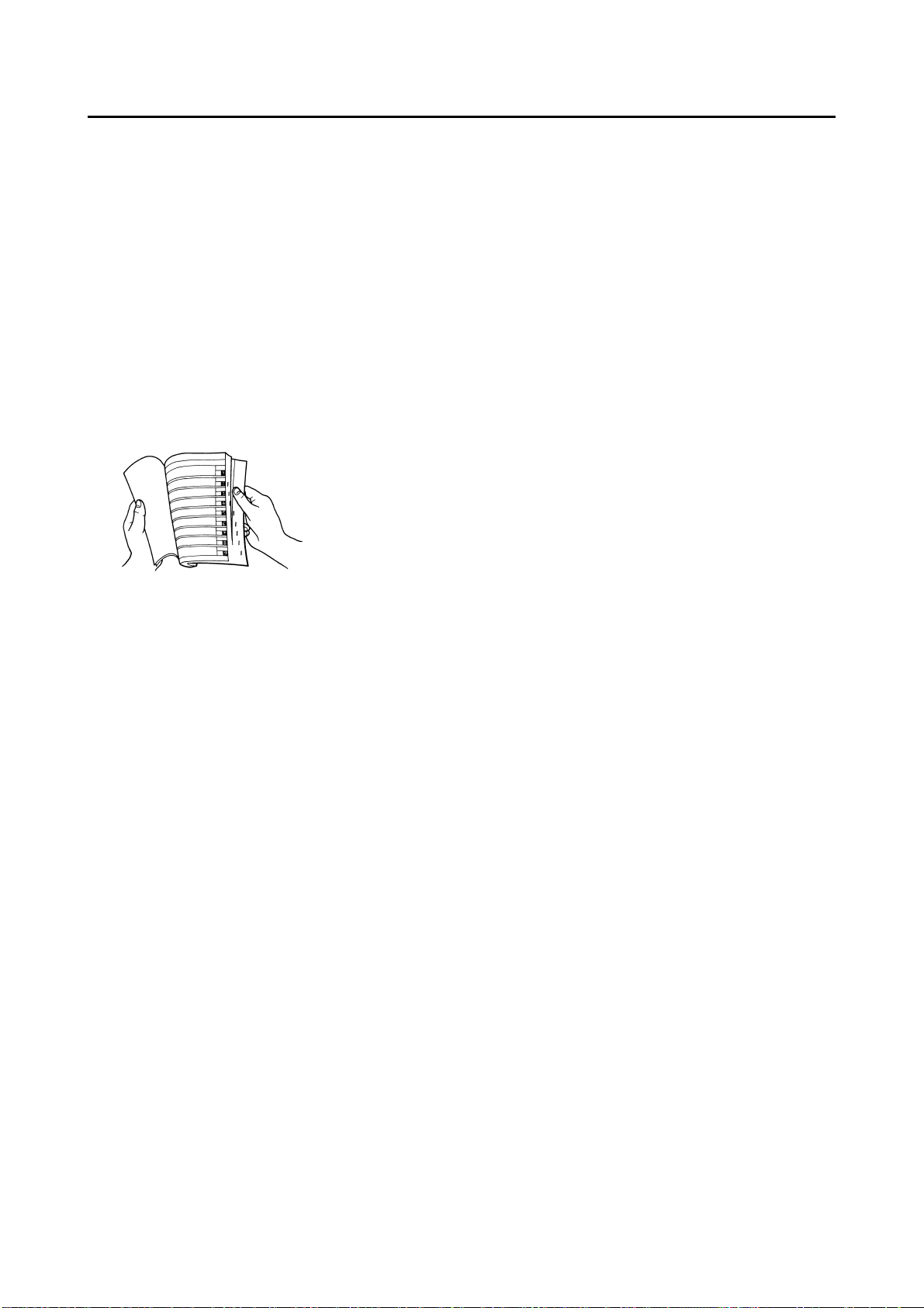
2. The table of contents is at the beginning of the manual. Look over
the general layout of the book before finding then required chapter
and item.
Bend the book at its edge, as
shown, to find the required fore
edge symbol mark and go to a
page for required item and description.
MANUAL FORMAT
All of the procedures in this manual
are organized in a sequential, stepby-step format. The information has
been complied to provide the mechanic with an easy to read, handy
reference that contains comprehensive explanations of all disassembly,
repair, assembly, and inspection operations.
In this revised format, the condition of
a faulty component will precede an
arrow symbol and the course of action required will follow the symbol,
e.g.,
• Bearings
Pitting/damage → Replace.
HOW TO READ DESCRIPTIONS
To help identify parts and clarify procedure steps, there are exploded diagrams at the start of each removal
and disassembly section.
1. An easy-to-see exploded diagram
"1" is provided for removal and
disassembly jobs.
2. MNumbers "2" are given in the order of the jobs in the exploded diagram. A number that is enclosed
by a circle indicates a disassembly step.
3. An explanation of jobs and notes
is presented in an easy-to-read
way by the use of symbol marks
"3". The meanings of the symbol
marks are given on the next page.
4. A job instruction chart "4" accompanies the exploded diagram,
providing the order of jobs, names
of parts, notes in jobs, etc.
5. For jobs requiring more information, the step-by-step format supplements "5" are given in addition
to the exploded diagram and job
instruction chart.
1
2
4
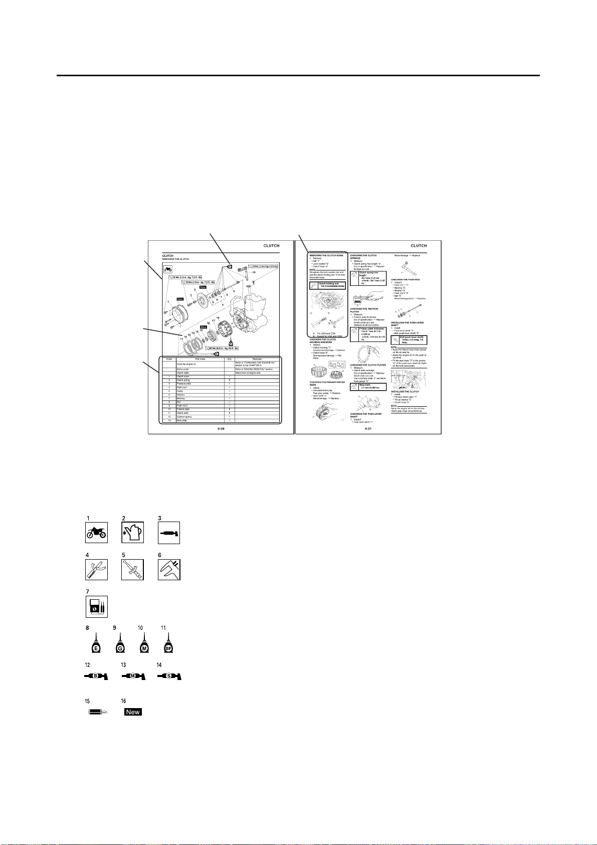
ILLUSTRATED SYMBOLS (Refer to
the illustration)
3
Illustrated symbols "1" to "7" are used
to identify the specifications appearing in the text.
1. With engine mounted
2. Filling fluid
3. Lubricant
4. Special tool
5. Tightening
6. Specified value, Service limit
7. Resistance (Ω), Voltage (V),
Electric current (A)
Illustrated symbols "8" to "14" in the
exploded diagrams indicate grade of
lubricant and location of lubrication
point.
8. Apply engine mixing oil
9. Apply transmission oil
10. Apply molybdenum disulfide oil
11. Apply brake fluid
12. Apply lightweight lithium-soap
base grease
13. Apply molybdenum disulfide
grease
5
14. Apply silicone grease
Illustrated symbols "15" to "16" in the
exploded diagrams indicate where to
apply a locking agent and where to install new parts.
15. Apply locking agent (LOC-
16. Use new one
TITE
®
)

TABLE OF CONTENTS
GENERAL INFORMATION
SPECIFICATIONS
REGULAR INSPECTION AND
ADJUSTMENTS
ENGINE
CHASSIS
1
2
3
4
5
ELECTRICAL
TUNING
6
7

CONTENTS
CHAPTER 1
GENERAL
INFORMATION
LOCATION OF
IMPORTANT LABELS ..... 1-1
DESCRIPTION ................. 1-5
CONSUMER
INFORMATION................. 1-6
INCLUDED PARTS ..........1-6
IMPORTANT
INFORMATION................. 1-6
CHECKING OF
CONNECTION.................. 1-7
SPECIAL TOOLS............. 1-8
CONTROL FUNCTIONS
........................................ 1-11
STARTING AND
BREAK-IN ......................1-11
TORQUE-CHECK
POINTS........................... 1-13
CLEANING AND
STORAGE ...................... 1-14
CHAPTER 2
SPECIFICATIONS
GENERAL
SPECIFICATIONS............ 2-1
MAINTENANCE
SPECIFICATIONS............ 2-3
TIGHTENING
TORQUES ........................ 2-8
CABLE
ROUTING DIAGRAM ..... 2-13
CHAPTER 3
REGULAR
INSPECTION AND
ADJUSTMENTS
MAINTENANCE
INTERVALS......................3-1
PRE-OPERATION
INSPECTION AND
MAINTENANCE................ 3-4
ENGINE ............................3-5
CHASSIS .......................... 3-8
ELECTRICAL .................3-19
CHAPTER 4
ENGINE
SEAT, FUEL TANK AND
SIDE COVERS..................4-1
EXHAUST PIPE AND
SILENCER ........................ 4-3
RADIATOR ....................... 4-5
CARBURETOR AND
REED VALVE ................... 4-7
CYLINDER HEAD,
CYLINDER AND PISTON
........................................4-13
CLUTCH .........................4-21
KICK SHAFT AND
SHIFT SHAFT.................4-25
YPVS GOVERNOR.........4-30
WATER PUMP................ 4-32
CDI MAGNETO...............4-35
ENGINE REMOVAL .......4-37
CRANKCASE AND
CRANKSHAFT ............... 4-41
TRANSMISSION,
SHIFT CAM AND
SHIFT FORK...................4-46
CHAPTER 5
CHASSIS
FRONT WHEEL AND
REAR WHEEL ..................5-1
FRONT BRAKE AND
REAR BRAKE ..................5-6
FRONT FORK.................5-16
HANDLEBAR..................5-24
STEERING ......................5-29
SWINGARM ....................5-32
REAR SHOCK
ABSORBER....................5-37
CHAPTER 6
ELECTRICAL
ELECTRICAL
COMPONENTS AND
WIRING DIAGRAM...........6-2
IGNITION SYSTEM...........6-3
SOLENOID VALVE
SYSTEM............................6-6
THROTTLE POSITION
SENSOR SYSTEM ...........6-8
CHAPTER 7
TUNING
ENGINE.............................7-1
CHASSIS ..........................7-6
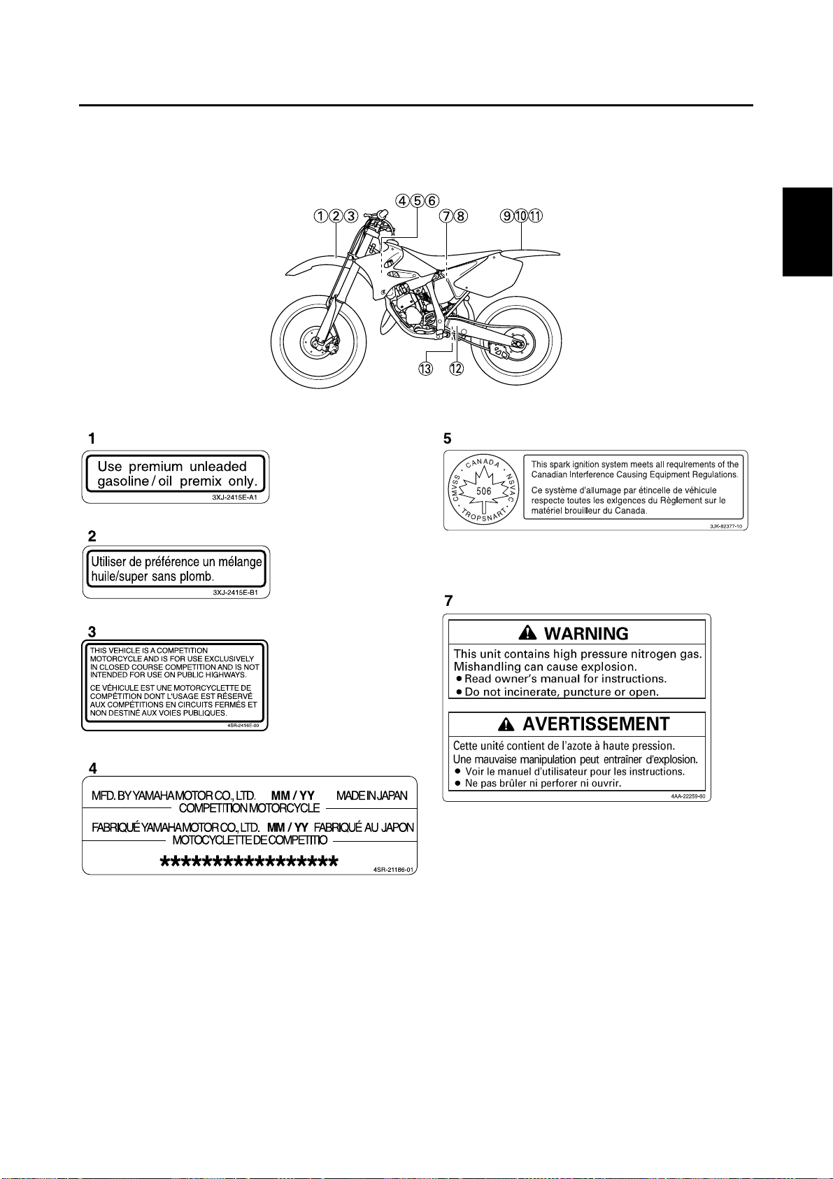
LOCATION OF IMPORTANT LABELS
GENERAL INFORMATION
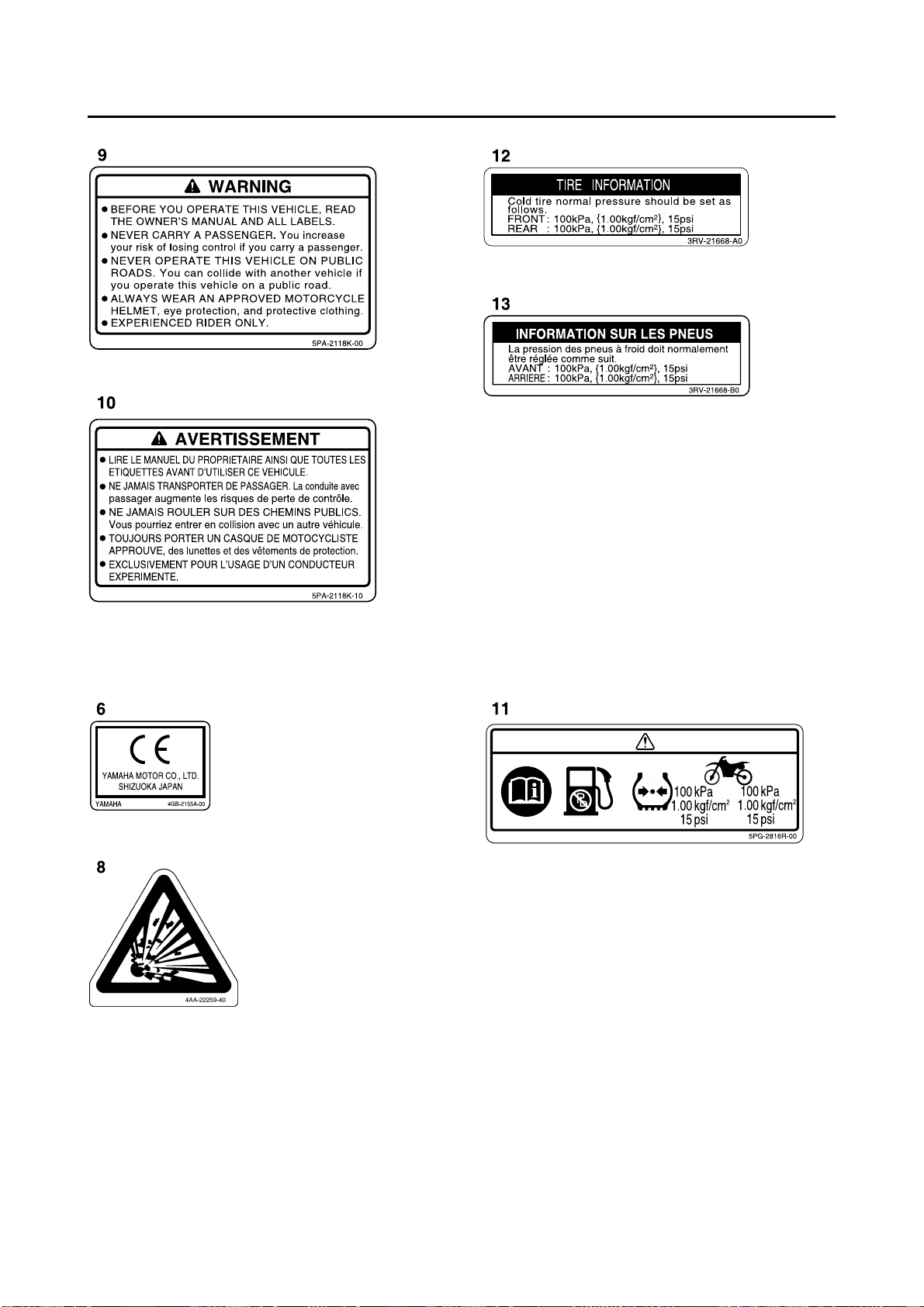
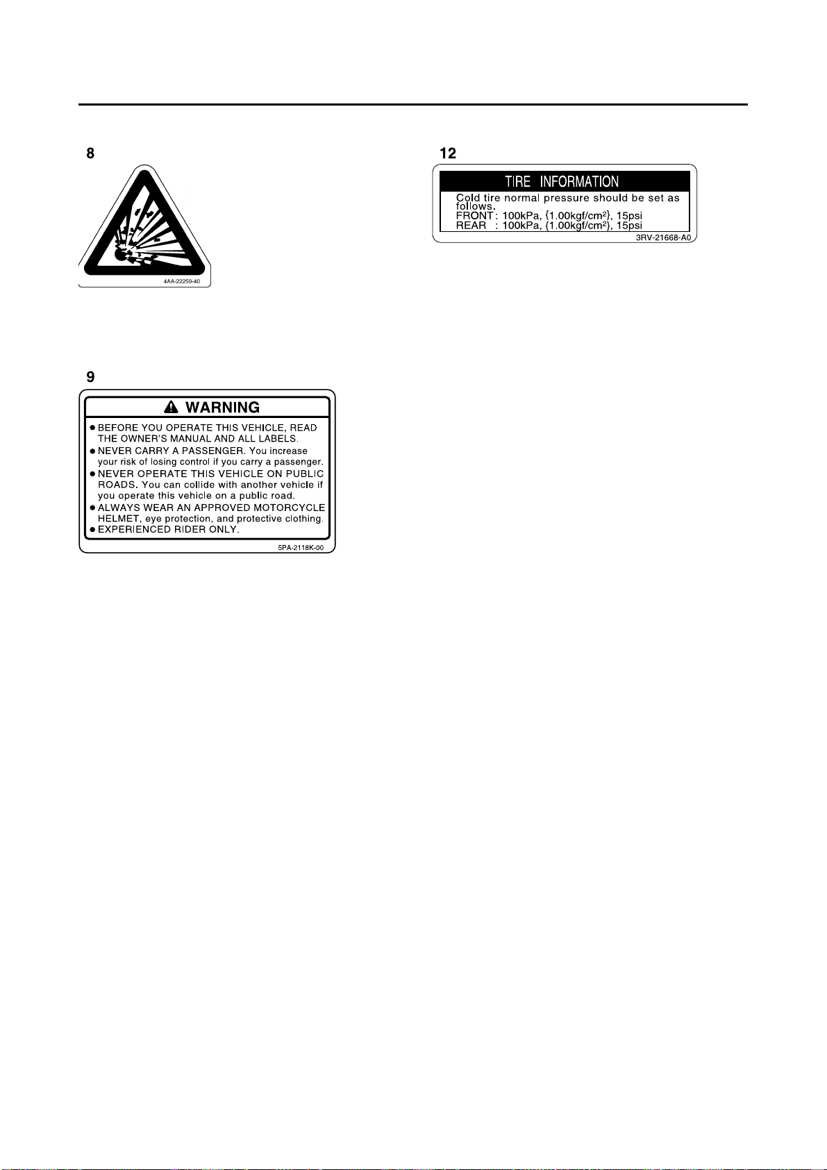
LOCATION OF IMPORTANT LABELS
Please read the following important labels carefully before operating this vehicle.
CANADA
1
1-1
LOCATION OF IMPORTANT LABELS
EUROPE
1-2
AUS, NZ, ZA
LOCATION OF IMPORTANT LABELS
1-3
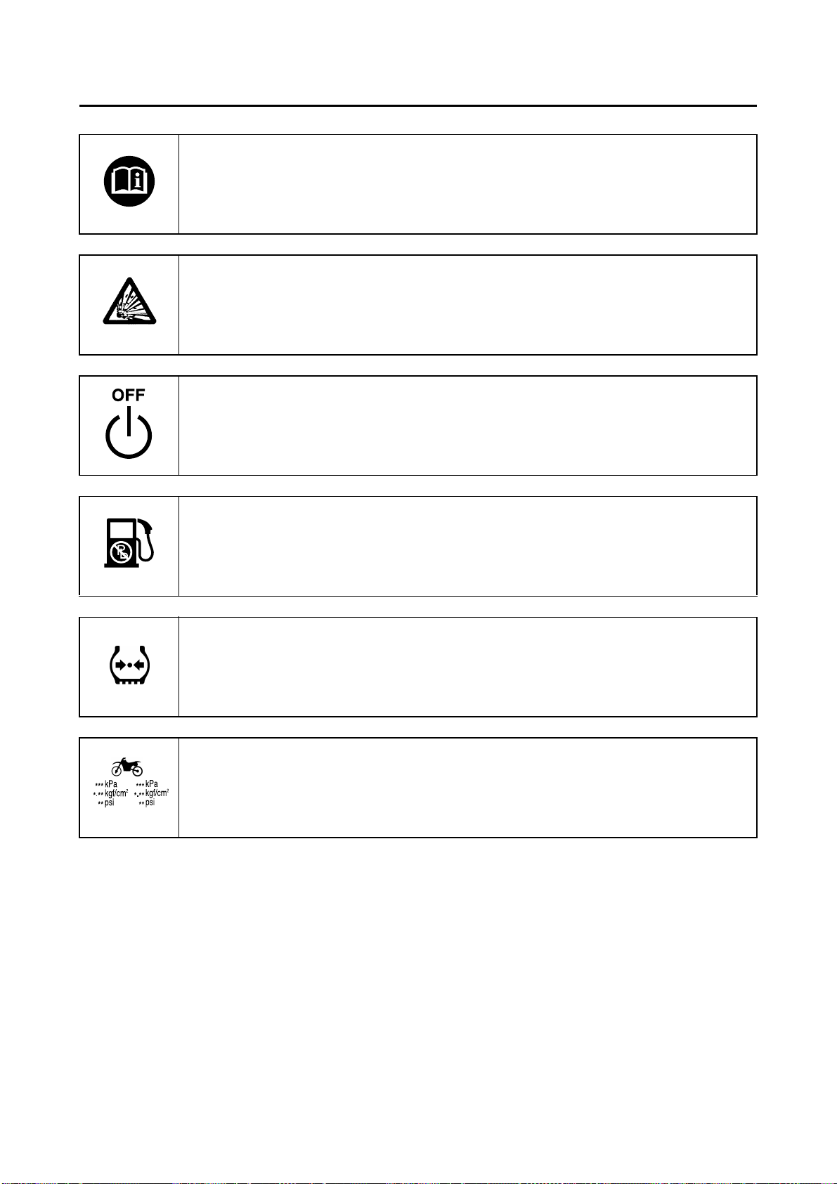
LOCATION OF IMPORTANT LABELS
Familiarize yourself with the following pictograms and read the explanatory text.
Read Owner’s service manual.
This unit contains high-pressure nitrogen gas. Mishandling can cause explosion. Do not incinerate,
puncture or open.
Turn off the main switch after riding to avoid draining the battery.
Use unleaded gasoline only.
Measure tire pressure when tires are cold.
Adjust tire pressure.
Improper tire pressure can cause loss of control.
Loss of control can result in severe injury or death.
1-4
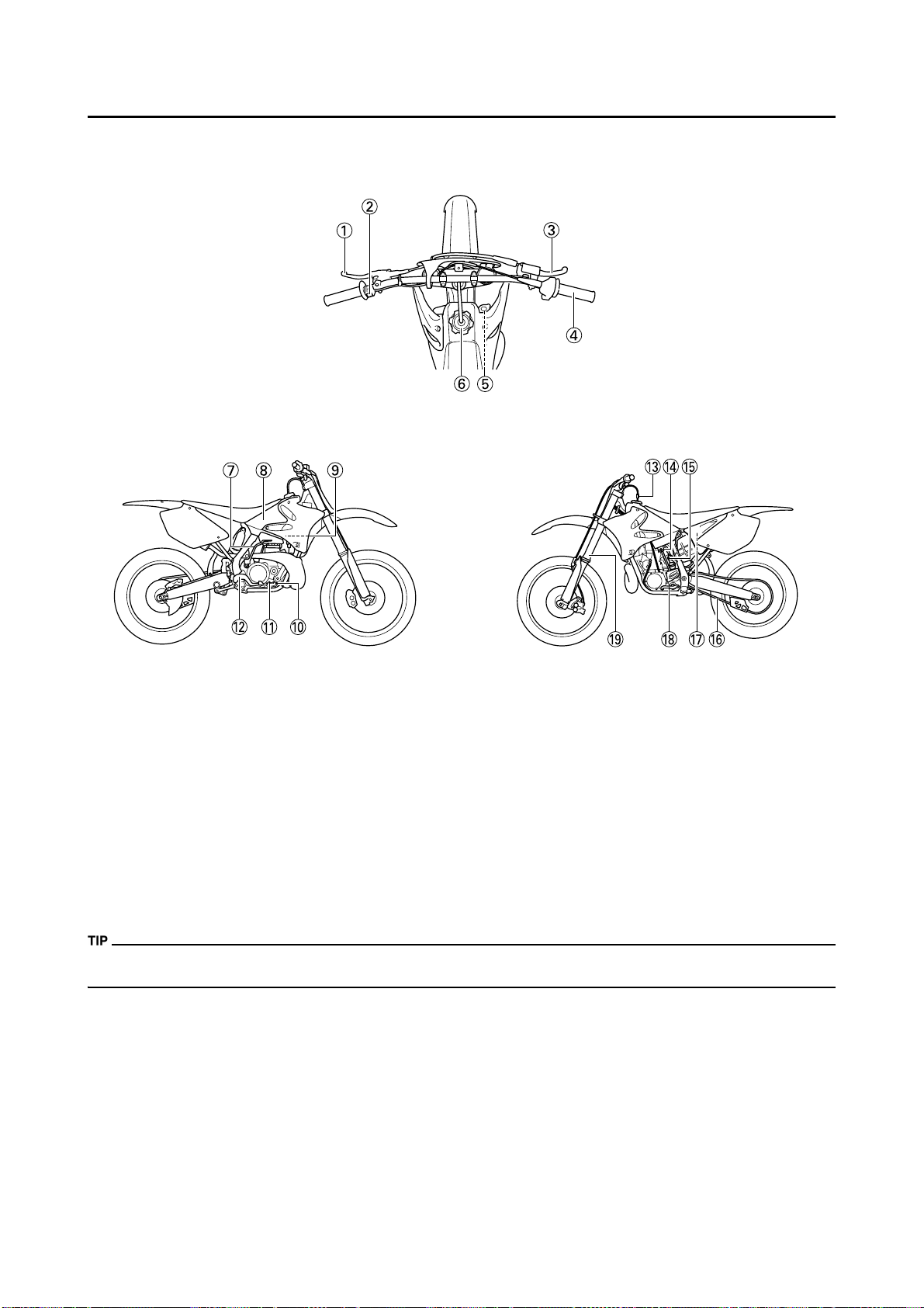
DESCRIPTION
DESCRIPTION
1. Clutch lever
2. Engine stop switch
3. Front brake lever
4. Throttle grip
5. Radiator cap
6. Fuel tank cap
7. Kickstarter crank
8. Fuel tank
9. Radiator
10. Coolant drain bolt
11. Check bolt (Transmission oil level)
12. Rear brake pedal
13. Valve joint
• The machine you have purchased may differ slightly from those shown in the following.
• Designs and specifications are subject to change without notice.
14. Fuel cock
15. Starter knob
16. Drive chain
17. Air filter
18. Shift pedal
19. Front fork
1-5
CONSUMER INFORMATION
CONSUMER INFORMATION
There are two significant reasons for
knowing the serial number of your
machine:
1. When ordering parts, you can
give the number to your Yamaha
dealer for positive identification of
the model you own.
2. If your machine is stolen, the authorities will need the number to
search for and identify your machine.
VEHICLE IDENTIFICATION
NUMBER
The vehicle identification number "1"
is stamped on the right of the steering
head pipe.
ENGINE SERIAL NUMBER
The engine serial number "1" is
stamped into the elevated part of the
right-side of the engine.
Silencer exhaust port
Side cover air intake port
Water pump housing hole at the
bottom
End of each hose
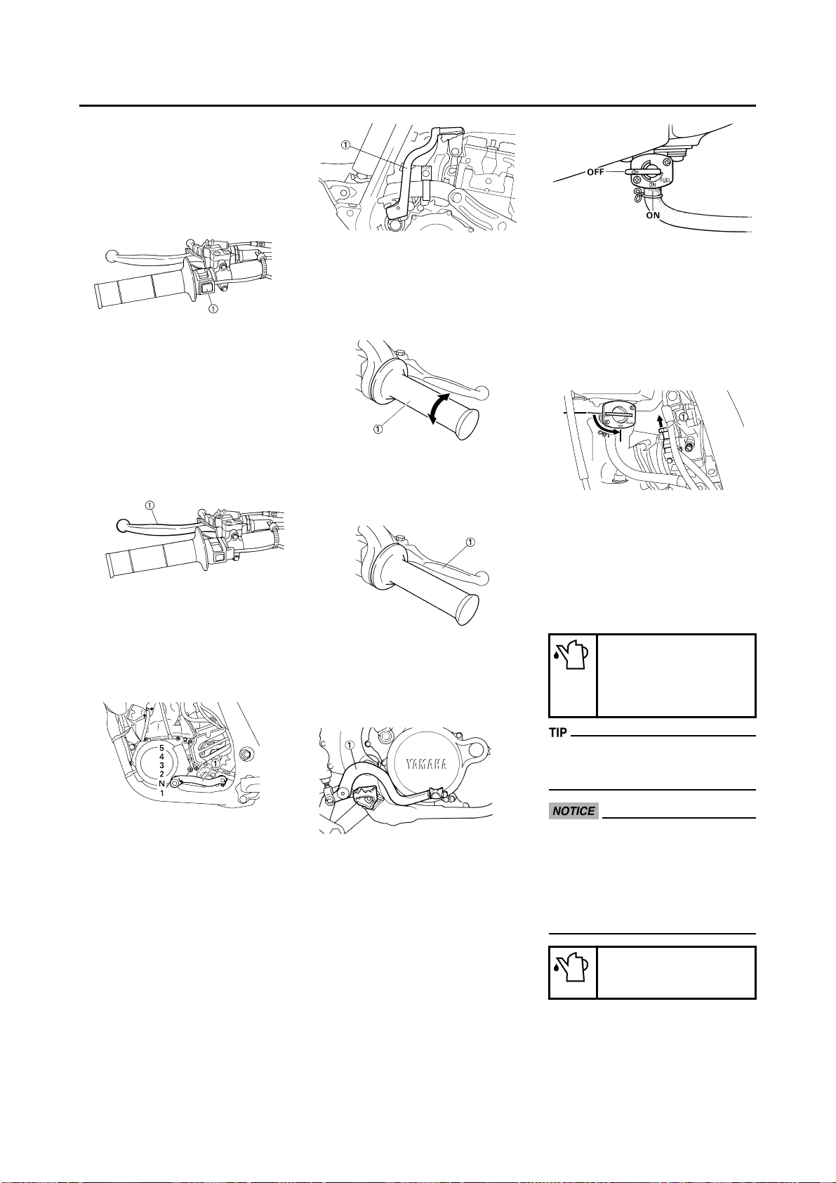
VALVE JOINT
This valve joint "1" prevents fuel from
flowing out and is installed to the fuel
tank breather hose.
In this installation, make sure the
arrow faces the fuel tank and also
downward.
2. Use proper tools and cleaning
equipment. Refer to "SPECIAL
TOOLS" section.
SET PIN
This set pin "1" is used to remove and
install the push rod of the engine.
MODEL LABEL
The model label "1" is affixed to the
frame under the rider's seat. This information will be needed to order
spare parts.
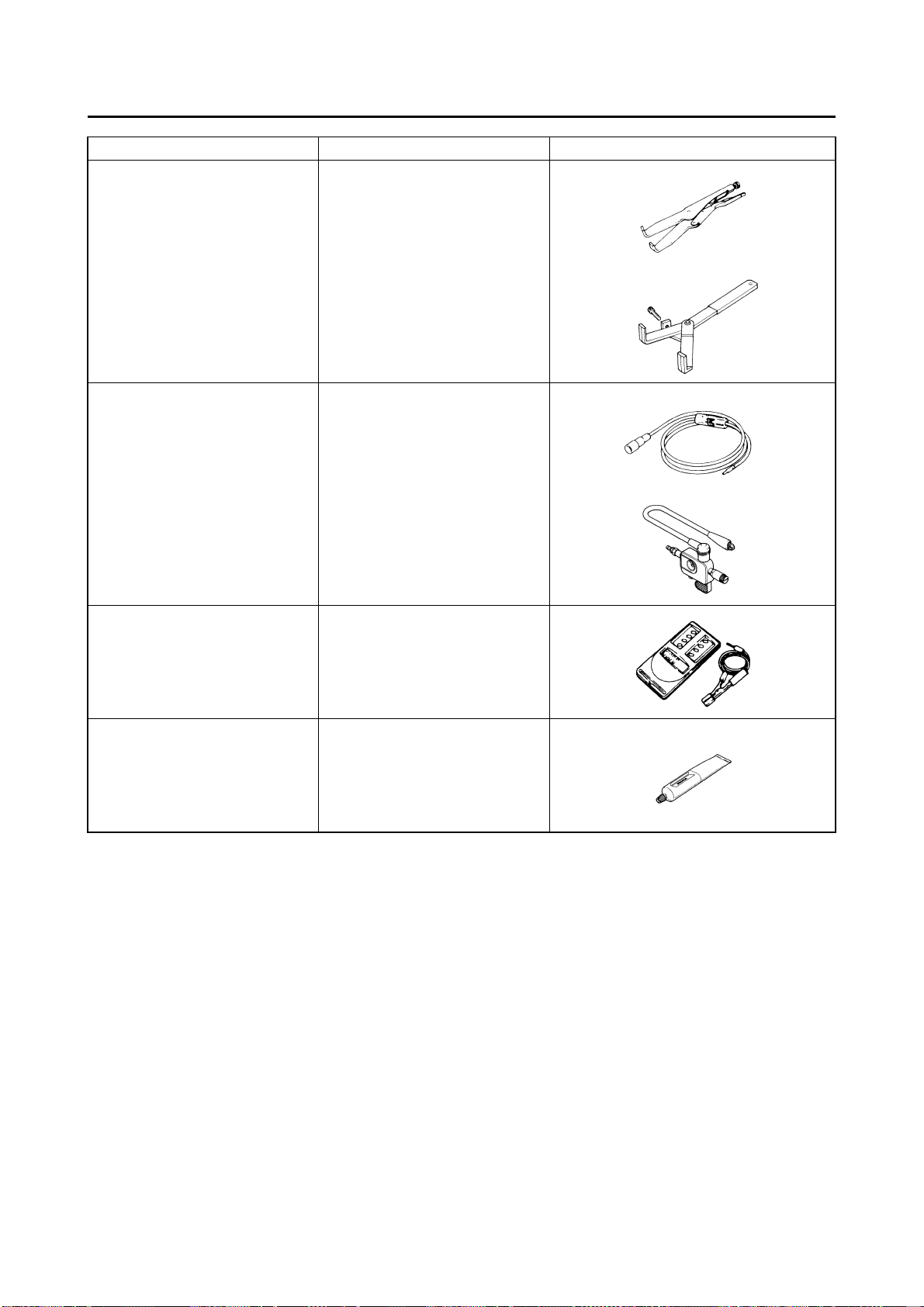
INCLUDED PARTS
DETACHABLE SIDESTAND
This sidestand "1" is used to support
only the machine when standing or
transporting it.
• Never apply additional force to
the sidestand.
• Remove this sidestand before
starting out.
Be sure to use the set pin. If the set
pin is not used, the power valve
constituent parts will result in
damage.
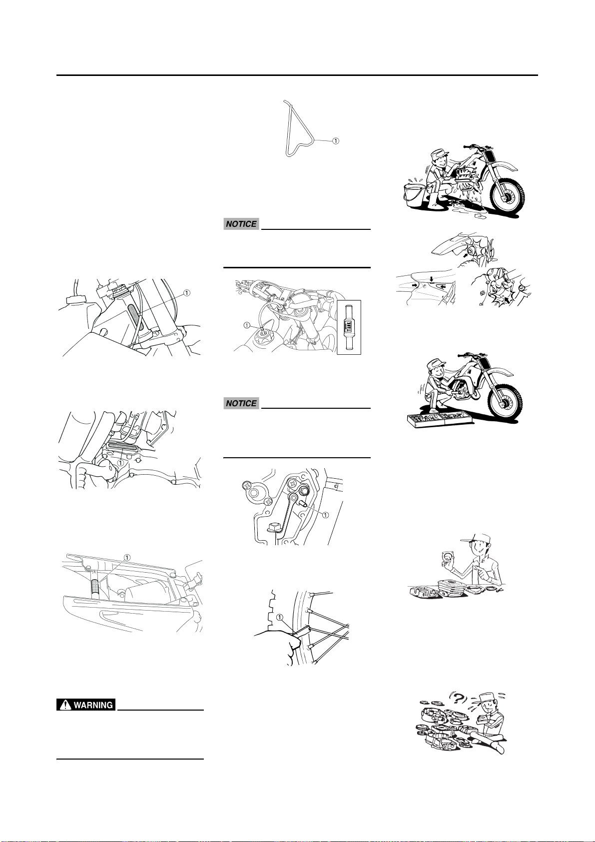
NIPPLE WRENCH
This nipple wrench "1" is used to
tighten the spoke.
IMPORTANT INFORMATION
PREPARATION FOR REMOVAL
AND DISASSEMBLY
1. Remove all dirt, mud, dust, and
foreign material before removal
and disassembly.
• When washing the machine with
high pressured water, cover the
parts follows.
3. When disassembling the machine, keep mated parts together.
They include gears, cylinders,
pistons, and other mated parts
that have been "mated" through
normal wear. Mated parts must
be reused as an assembly or replaced.
4. During the machine disassembly,
clean all parts and place them in
trays in the order of disassembly.
This will speed up assembly time
and help assure that all parts are
correctly reinstalled.
5. Keep away from fire.
1-6
CHECKING OF CONNECTION
ALL REPLACEMENT PARTS
1. We recommend to use Yamaha
genuine parts for all replacements. Use oil and/or grease recommended by Yamaha for
assembly and adjustment.
GASKETS, OIL SEALS AND ORINGS
1. All gaskets, oil seals, and O-rings
should be replaced when an engine is overhauled. All gasket surfaces, oil seal lips, and O-rings
must be cleaned.
2. Properly oil all mating parts and
bearings during reassembly. Apply grease to the oil seal lips.
LOCK WASHERS/PLATES AND
COTTER PINS
1. All lock washers/plates "1" and
cotter pins must be replaced
when they are removed. Lock
tab(s) should be bent along the
bolt or nut flat(s) after the bolt or
nut has been properly tightened.
BEARINGS AND OIL SEALS
1. Install the bearing(s) "1" and oil
seal(s) "2" with their manufacturer's marks or numbers facing outward. (In other words, the
stamped letters must be on the
side exposed to view.) When installing oil seal(s), apply a light
coating of lightweight lithium base
grease to the seal lip(s). Oil the
bearings liberally when installing.
Do not use compressed air to spin
the bearings dry. This causes damage to the bearing surfaces.
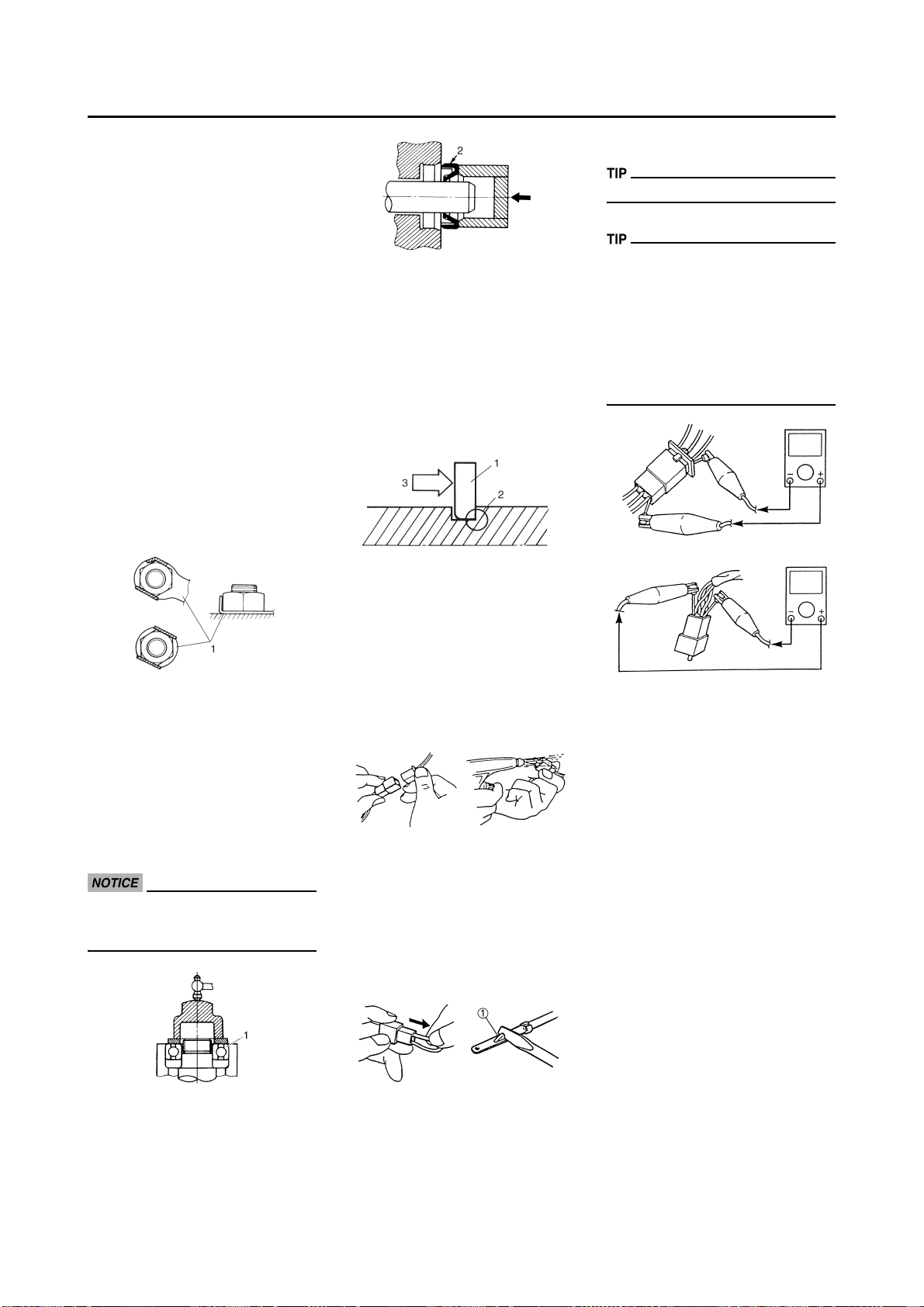
CIRCLIPS
1. All circlips should be inspected
carefully before reassembly. Always replace piston pin clips after
one use. Replace distorted circlips. When installing a circlip "1",
make sure that the sharp-edged
corner "2" is positioned opposite
to the thrust "3" it receives. See
the sectional view.
CHECKING OF
CONNECTION
Dealing with stains, rust, moisture,
etc. on the connector.
1. Disconnect:
• Connector
2. Dry each terminal with an air
blower.
3. Connect and disconnect the connector two or three times.
4. Pull the lead to check that it will
not come off.
5. If the terminal comes off, bend up
the pin "1" and reinsert the terminal into the connector.
6. Connect:
• Connector
The two connectors "click" together.
7. Check for continuity with a tester.
• If there in no continuity, clean the
terminals.
• Be sure to perform the steps 1 to 7
listed above when checking the
wire harness.
• For a field remedy, use a contact revitalizer available on the market.
• Use the tester on the connector as
shown.
1-7
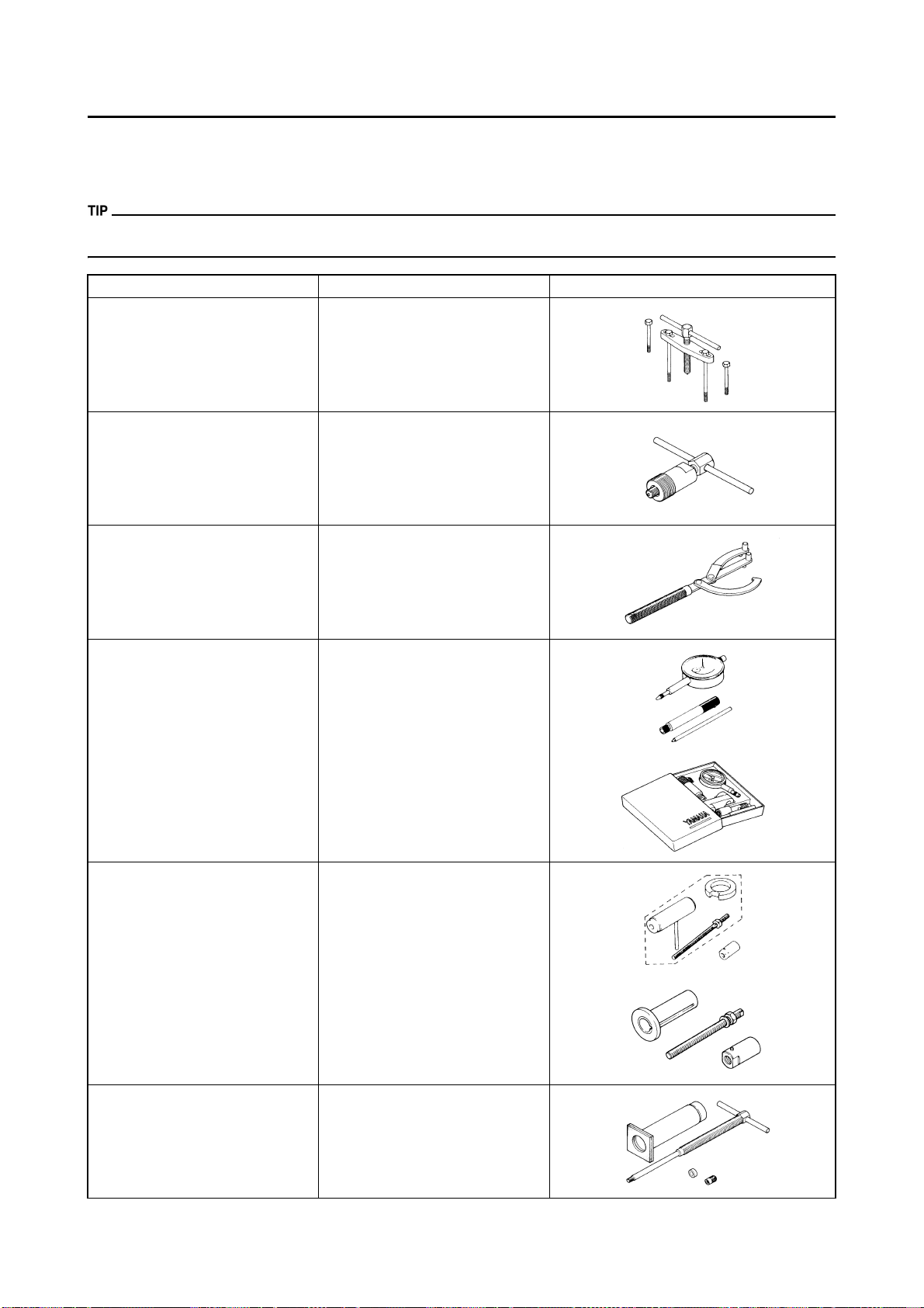
SPECIAL TOOLS
SPECIAL TOOLS
The proper special tools are necessary for complete and accurate tune-up and assembly. Using the correct special tool will
help prevent damage caused by the use of improper tools or improvised techniques. The shape and part number used for
the special tool differ by country, so two types are provided. Refer to the list provided to avoid errors when placing an order.
• For U.S.A. and Canada, use part number starting with "YM-", "YU-" or "ACC-".
• For others, use part number starting with "90890-".
Tool name/Part number How to use Illustration
Crankcase separating tool
YU-1135-A, 90890-01135
These tool is used to remove the
crankshaft from either case.
Flywheel puller
YM-1189, 90890-01189
Rotor holding tool
YU-1235, 90890-01235
Dial gauge and stand
YU-3097, 90890-01252
Stand
YU-1256
Crankshaft installing tool
Crankshaft installing pot
YU-90050, 90890-01274
Crankshaft installing bolt
YU-90050, 90890-01275
Adapter
YU-90063, 90890-01278
This tool is used to remove the flywheel magneto.
This tool is used when loosening or
tightening the flywheel magneto securing nut.
These tools are used to check each
part for runout or bent.
These tools are used to install the
crankshaft.
Piston pin puller set
YU-1304, 90890-01304
This tool is used to remove the piston pin.
1-8
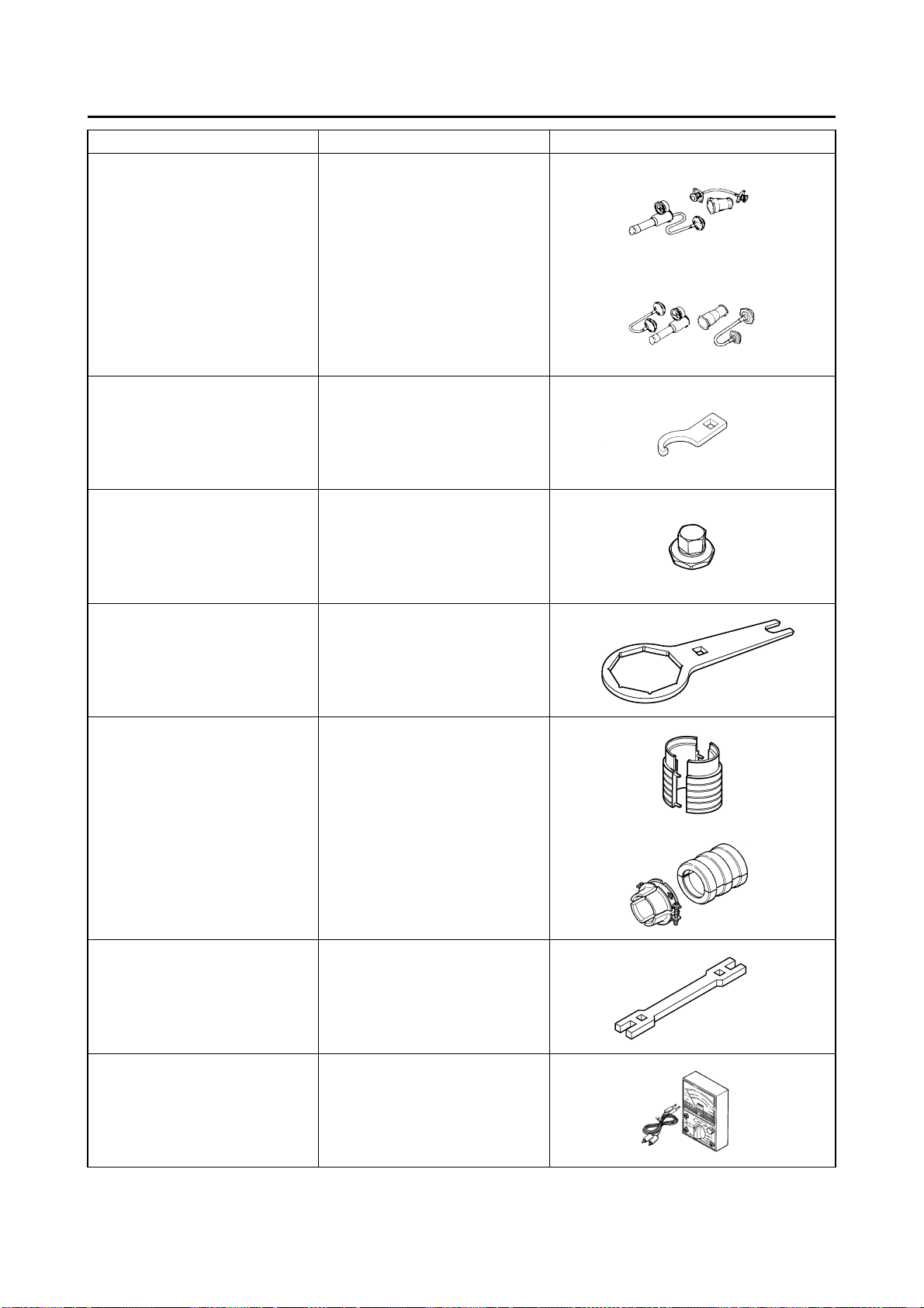
SPECIAL TOOLS
Tool name/Part number How to use Illustration
Radiator cap tester
YU-24460-01, 90890-01325
Radiator cap tester adapter
YU-33984, 90890-01352
These tools are used for checking
the cooling system.
Steering nut wrench
YU-33975, 90890-01403
Cap bolt wrench
YM-01500, 90890-01500
Cap bolt ring wrench
YM-01501, 90890-01501
Fork seal driver
YM-A0948, 90890-01502
This tool is used when tighten the
steering ring nut to specification.
This tool is used to loosen or tighten
the base valve.
This tool is used to loosen or tighten
the damper assembly.
This tool is used when install the fork
oil seal.
Spoke nipple wrench
YM-01521, 90890-01521
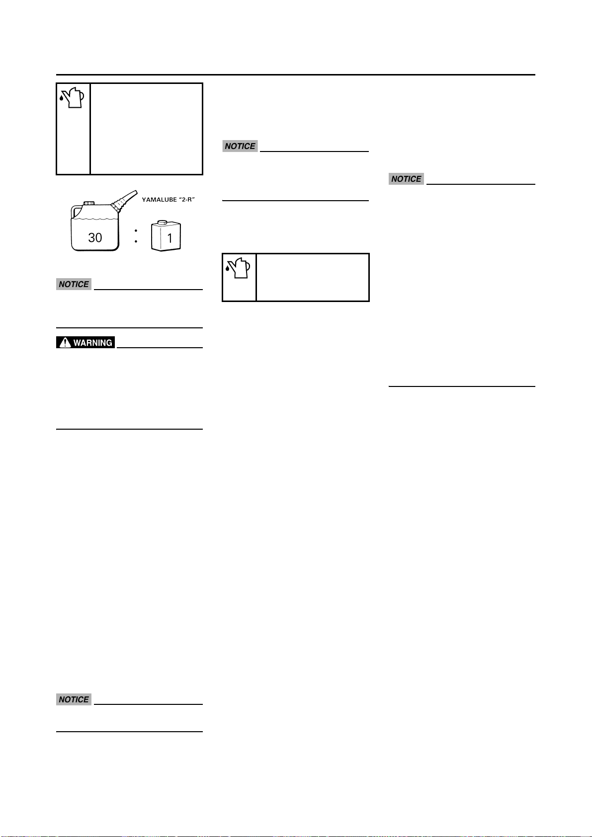
Pocket tester
YU-3112-C, 90890-03112
This tool is used to tighten the
spoke.
Use this tool to inspect the coil resistance, output voltage and amperage.
1-9
SPECIAL TOOLS
Tool name/Part number How to use Illustration
Clutch holding tool
YM-91042, 90890-04086
This tool is used to hold the clutch
when removing or installing the
clutch boss securing nut.
Dynamic spark tester
YM-34487
Ignition checker
90890-06754
Digital tachometer
YU-39951-B, 90890-06760
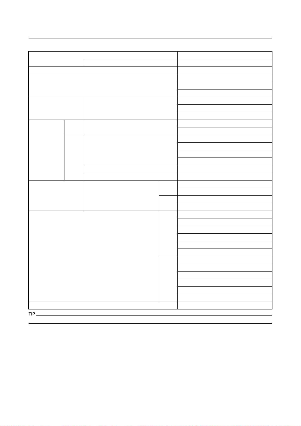
YAMAHA Bond No. 1215 (Three-
®
No. 1215)
Bond
90890-85505
This instrument is necessary for
checking the ignition system components.
This tool is needed for observing engine rpm.
This sealant (Bond) is used for
crankcase mating surface, etc.
1-10
CONTROL FUNCTIONS
ENGINE STOP SWITCH
The engine stop switch "1" is located
on the left handlebar. Continue pushing the engine stop switch till the engine comes to a stop.
CONTROL FUNCTIONS
CLUTCH LEVER
The clutch lever "1" is located on the
left handlebar; it disengages or engages the clutch. Pull the clutch lever
to the handlebar to disengage the
clutch, and release the lever to engage the clutch. The lever should be
pulled rapidly and released slowly for
smooth starts.
SHIFT PEDAL
The gear ratios of the constant-mesh
5 speed transmission are ideally
spaced. The gears can be shifted by
using the shift pedal "1" on the left
side of the engine.
THROTTLE GRIP
The throttle grip "1" is located on the
right handlebar; it accelerates or decelerates the engine. For acceleration, turn the grip toward you; for
deceleration, turn it away from you.
FRONT BRAKE LEVER
The front brake lever "1" is located on
the right handlebar. Pull it toward the
handlebar to activate the front brake.
REAR BRAKE PEDAL
The rear brake pedal "1" is located on
the right side of the machine. Press
down on the brake pedal to activate
the rear brake.
STARTER KNOB (CHOKE)
When cold, the engine requires a
richer air-fuel mixture for starting. A
separate starter circuit, which is controlled by the starter knob "1", supplies this mixture. Pull the starter
knob out to open the circuit for starting. When the engine has warmed
up, push it in to close the circuit.
STARTING AND BREAK-IN
FUEL
Mix oil with the gas at the ratio specified below. Always use fresh, namebrand gasoline, and mix the oil and
gas the day of the race. Do not use
premix that is more than a few hours
old.
Recommended fuel:
Premium unleaded
gasoline only with a research octane number
of 95 or higher.
KICKSTARTER CRANK
Rotate the kickstarter crank "1" away
from the engine. Push the starter
down lightly with your foot until the
gears engage, then kick smoothly
and forcefully to start the engine. This
model has a primary kickstarter crank
so the engine can be started in any
gear if the clutch is disengaged. In
normal practices, however, shift to
neutral before starting.
FUEL COCK
The fuel cock supplies fuel from the
tank to carburetor and also filters the
fuel. The fuel cock has the two positions:
OFF:
With the lever in this position, fuel will
not flow. Always return the lever to
this position when the engine is not
running.
ON:
With the lever in this position, fuel
flows to the carburetor. Normal riding
is done with the lever in this position.
1-11
If knocking or pinging occurs, use a
different brand of gasoline or higher
octane grade.
Never mix two types of oil in the
same batch; clotting of the oil
could result. If you wish to change
oil types, be sure to drain the fuel
tank and the carburetor float bowl
of old premix prior to filling with
the new type.
Fuel tank capacity:
8.0 L (1.76 Imp gal, 2.11
US gal)
STARTING AND BREAK-IN
Mixing oil:
Recommended oil:
Yamalube "2-R"
(Yamalube racing 2cycle oil)
Mixing ratio: 30:1
If unavailable, use an
equivalent type of oil.
HANDLING NOTE
Before starting the machine, perform the checks in the pre-operation check list.
Never start or run the engine in a
closed area. The exhaust fumes
are poisonous; they can cause
loss of consciousness and death
in a very short time. Always operate the machine in a well-ventilated
area.
AIR FILTER MAINTENANCE
According to "CLEANING THE AIR
FILTER ELEMENT" section in the
CHAPTER 3, apply the foam-air-filter
oil or its equivalent to the element.
(Excess oil in the element may adversely affect engine starting.)
STARTING A COLD ENGINE
1. Shift the transmission into neutral.
2. Turn the fuel cock to "ON" and full
open the starter knob (CHOKE).
3. With the throttle completely
closed start the engine by kicking
the kick starter forcefully with firm
stroke.
4. Run the engine at idle or slightly
higher until it warms up: this usually takes about one or two minutes.
5. The engine is warmed up when it
responds normally to the throttle
with the starter knob (CHOKE)
turned off.
STARTING A WARM ENGINE
Do not operate the starter knob
(CHOKE). Open the throttle slightly
and start the engine by kicking the
kick starter forcefully with firm stroke.
Observe the following break-in
procedures during initial operation
to ensure optimum performance
and avoid engine damage.
BREAK-IN PROCEDURES
1. Before starting the engine, fill the
fuel tank with a break-in oil-fuel
mixture as follows.
Mixing oil:
Yamalube "2-R"
Mixing ratio:
15:1
2. Perform the pre-operation checks
on the machine.
3. Start and warm up the engine.
Check the idle speed, and check
the operation of the controls and
the "ENGINE STOP" button.
4. Operate the machine in the lower
gears at moderate throttle openings for five to eight minutes. Stop
and check the spark plug condition; it will show a rich condition
during break-in.
5. Allow the engine to cool. Restart
the engine and operate the machine as in the step above for five
minutes. Then, very briefly shift to
the higher gears and check fullthrottle response. Stop and check
the spark plug.
6. After again allowing the engine to
cool, restart and run the machine
for five more minutes. Full throttle
and the higher gears may be
used, but sustained full-throttle
operation should be avoided.
Check the spark plug condition.
7. Allow the engine to cool, remove
the top end, and inspect the piston and cylinder. Remove any
high spots on the piston with #600
grit wet sandpaper. Clean all
components and carefully reassemble the top end.
8. Drain the break-in oil-fuel mixture
from the fuel tank and refill with
the specified mix.
9. Restart the engine and check the
operation of the machine throughout its entire operating range.
Stop and check the spark plug
condition. Restart the machine
and operate it for about 10 to 15
more minutes. The machine will
now be ready to race.
• After the break-in or before each
race, you must check the entire
machine for loose fittings and
fasteners as per "TORQUECHECK POINTS". Tighten all
such fasteners as required.
• When any of the following parts
have been replaced, they must
be broken in.
CYLINDER AND CRANKSHAFT:
About one hour of break-in operation is necessary.
PISTON, RING AND GEARS:
These parts require about 30
minutes of break-in operation at
half-throttle or less. Observe the
condition of the engine carefully
during operation.
Do not warm up the engine for extended periods of time.
1-12
TORQUE-CHECK POINTS
TORQUE-CHECK POINTS
Frame construction Frame to rear frame
Combined seat and fuel tank Fuel tank to frame
Exhaust system Silencer to rear frame
Engine mounting Frame to engine
Engine bracket to engine
Engine bracket to frame
Steering Steering stem to handlebar Steering stem to frame
Steering stem to upper bracket
Upper bracket to handlebar
Suspension Front Steering stem to front fork Front fork to upper bracket
Front fork to lower bracket
Rear For link type Assembly of links
Link to frame
Link to rear shock absorber
Link to swingarm
Installation of rear shock absorber Rear shock absorber to frame
Installation of swingarm Tightening of pivot shaft
Wheel Installation of wheel Front Tightening of wheel axle
Tightening of axle holder
Rear Tightening of wheel axle
Wheel to rear wheel sprocket
Brake Front Brake caliper to front fork
Brake disc to wheel
Tightening of union bolt
Brake master cylinder to handlebar
Tightening of bleed screw
Tightening of brake hose holder
Rear Brake pedal to frame
Brake disc to wheel
Tightening of union bolt
Brake master cylinder to frame
Tightening of bleed screw
Tightening of brake hose holder
Fuel system Fuel tank to fuel cock
Concerning the tightening torque, refer to "TIGHTENING TORQUES" section in the CHAPTER 2.
1-13

CLEANING AND STORAGE
CLEANING AND STORAGE
CLEANING
Frequent cleaning of your machine
will enhance its appearance, maintain
good overall performance, and extend the life of many components.
1. Before washing the machine,
block off the end of the exhaust
pipe to prevent water from entering. A plastic bag secured with a
rubber band may be used for this
purpose.
2. If the engine is excessively
greasy, apply some degreaser to
it with a paint brush. Do not apply
degreaser to the chain, sprockets,
or wheel axles.
3. Rinse the dirt and degreaser off
with a garden hose; use only
enough pressure to do the job.
Do not use high-pressure washers
or steam-jet cleaners since they
cause water seepage and deterioration seals.
4. After the majority of the dirt has
been hosed off, wash all surfaces
with warm water and a mild detergent. Use an old toothbrush to
clean hard-to-reach places.
5. Rinse the machine off immediately with clean water, and dry all
surfaces with a soft towel or cloth.
6. Immediately after washing, remove excess water from the
chain with a paper towel and lubricate the chain to prevent rust.
7. Clean the seat with a vinyl upholstery cleaner to keep the cover
pliable and glossy.
8. Automotive wax may be applied
to all painted or chromed surfaces. Avoid combination cleanerwaxes, as they may contain abrasives.
9. After completing the above, start
the engine and allow it to idle for
several minutes.
STORAGE
If your machine is to be stored for 60
days or more, some preventive measures must be taken to avoid deterioration. After cleaning the machine
thoroughly, prepare it for storage as
follows:
1. Drain the fuel tank, fuel lines, and
the carburetor float bowl.
2. Remove the spark plug, pour a tablespoon of SAE 10W-40 motor
oil in the spark plug hole, and reinstall the plug. With the engine
stop switch pushed in, kick the engine over several times to coat the
cylinder walls with oil.
3. Remove the drive chain, clean it
thoroughly with solvent, and lubricate it. Reinstall the chain or store
it in a plastic bag tied to the frame.
4. Lubricate all control cables.
5. Block the frame up to raise the
wheels off the ground.
6. Tie a plastic bag over the exhaust
pipe outlet to prevent moisture
from entering.
7. If the machine is to be stored in a
humid or salt-air environment,
coat all exposed metal surfaces
with a film of light oil. Do not apply
oil to rubber parts or the seat cover.
Make any necessary repairs before
the machine is stored.
1-14
GENERAL SPECIFICATIONS
SPECIFICATIONS
GENERAL SPECIFICATIONS
Model name: YZ250A1 (USA, CDN)
YZ250 (EUROPE, ZA)
YZ250A (AUS, NZ)
Model code number: 1P8S (USA, CDN)
1P8T (EUROPE)
1P8V (AUS, NZ, ZA)
Dimensions: USA, AUS, NZ, ZA EUROPE, CDN
Overall length 2,178 mm (85.7 in) 2,184 mm (86.0 in)
Overall width 827 mm (32.6 in) ←
Overall height 1,306 mm (51.4 in) 1,309 mm (51.5 in)
Seat height 994 mm (39.1in) 997 mm (39.3 in)
Wheelbase 1,481 mm (58.3 in) ←
Minimum ground clearance 382 mm (15.0 in) 385 mm (15.2 in)
Weight:
With oil and fuel 103 kg (227 lb)
Engine:
Engine type Liquid cooled 2-stroke, gasoline
Cylinder arrangement Single cylinder, forward inclined
3
Displacement 249 cm
Bore × stroke 66.4 × 72 mm (2.614 × 2.835 in)
Compression ratio 8.9–10.6 : 1
Starting system Kick starter
Lubrication system: Premix (30 : 1)(Yamalube 2-R)
Oil type or grade (2-stroke):
Transmission oil Recommended brand: YAMALUBE
SAE10W-40
API service SG type or higher
JASO standard MA
Periodic oil change 0.75 L (0.66 Imp qt, 0.79 US qt)
Total amount 0.80 L (0.70 Imp qt, 0.85 US qt)
Coolant capacity (including all routes): 1.20 L (1.06 Imp qt, 1.27 US qt)
Air filter: Wet type element
Fuel:
Type Premium unleaded gasoline only with a research octane
number of 95 or higher.
Tank capacity 8.0 L (1.76 Imp gal, 2.11 US gal)
Carburetor:
Type/Manufacturer PWK38S/KEIHIN
Spark plug:
Type/Manufacturer BR8EG/NGK (resistance type)
Gap 0.5–0.6 mm (0.020–0.024 in)
Clutch type: Wet, multiple-disc
(8.76 Imp oz, 8.42 US oz)
2
2-1

GENERAL SPECIFICATIONS
Transmission:
Primary reduction system Gear
Primary reduction ratio 63/21 (3.000)
Secondary reduction system Chain drive
Secondary reduction ratio 50/14 (3.571)
Transmission type Constant mesh, 5-speed
Operation Left foot operation
Gear ratio:
1st 27/14 (1.929)
2nd 23/15 (1.533)
3rd 23/18 (1.278)
4th 24/22 (1.091)
5th 20/21 (0.952)
Chassis: USA, ZA, AUS, NZ EUROPE, CDN
Frame type Semi double cradle ←
Caster angle 26.9 ° 27.1 °
Trail 115 mm (4.53 in) 118 mm (4.65 in)
Tire:
Type With tube
Size (front) 80/100-21 51M
Size (rear) 110/90-19 62M
2
Tire pressure (front and rear) 100 kPa (1.0 kgf/cm
Brake:
Front brake type Single disc brake
Operation Right hand operation
Rear brake type Single disc brake
Operation Right foot operation
Suspension:
Front suspension Telescopic fork
Rear suspension Swingarm (link type monocross suspension)
Shock absorber:
Front shock absorber Coil spring/oil damper
Rear shock absorber Coil spring/gas, oil damper
Wheel travel:
Front wheel travel 300 mm (11.8 in)
Rear wheel travel 315 mm (12.4 in)
Electrical:
Ignition system CDI magneto
, 15 psi)
2-2
MAINTENANCE SPECIFICATIONS
MAINTENANCE SPECIFICATIONS
ENGINE
Item Standard Limit
Cylinder head:
3
Combustion chamber capacity 21.5 cm
Warp limit ---- 0.03 mm
Cylinder:
Bore size 66.400–66.414 mm (2.6142–2.6147 in) 66.5 mm
Taper limit ---- 0.05 mm
Out of round limit ---- 0.01 mm
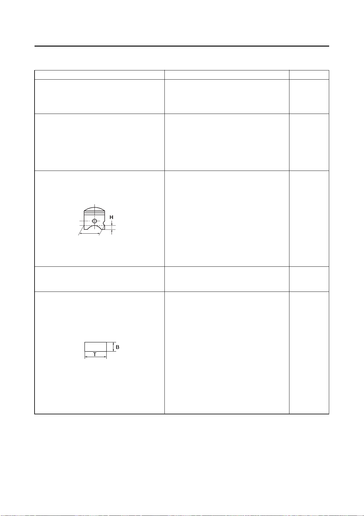
Piston:
Piston size/ 66.352–66.367 mm (2.6120–2.6129 in) ----
Measuring point "H" 17.5 mm (0.69 in) ----
(0.757 Imp oz, 0.727 US oz) ----
(0.0012 in)
(2.1618 in)
(0.0020 in)
(0.0004 in)
Piston clearance 0.045–0.050 mmm (0.0018–0.0020 in) 0.1 mm (0.004
in)
Piston offset 1.5 mm (0.059 in)/EX-side ----
Piston pin:
Piston pin outside diameter 17.995–18.000 mm (0.7085–0.7087 in) 17.975 mm
(0.7077 in)
Piston ring:
Sectional sketch Plain ----
B=1.0 mm (0.039 in) ----
T=2.55 mm (0.100 in) ----
End gap (installed) 0.40–0.55 mm (0.016–0.022 in) 0.95 mm
(0.037 in)
Side clearance (installed) :1st 0.030–0.065 mm (0.0012–0.0026 in) 0.1 mm (0.004
in)
Side clearance (installed) :2nd 0.030–0.065 mm (0.0012~0.0026 in) 0.1 mm (0.004
in)
2-3
MAINTENANCE SPECIFICATIONS
Item Standard Limit
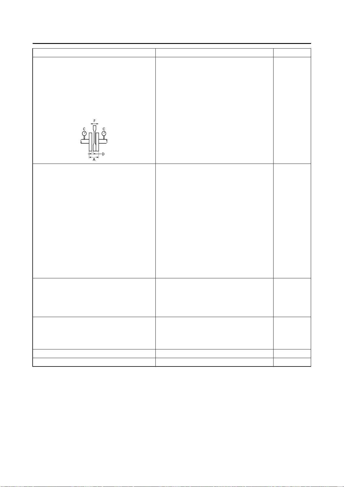
Crankshaft:
Crank width "A" 59.95–60.00 mm (2.360–2.362 in) ----
Runout limit "C" 0.03 mm (0.0012 in) 0.05 mm
(0.0020 in)
Connecting rod big end side clearance "D" 0.25–0.75 mm (0.010–0.030 in) ----
Small end free play "F" 0.4–1.0 mm (0.016–0.039 in) 2.0 mm (0.08
in)
Clutch:
Friction plate thickness 2.9–3.1 mm (0.114–0.122 in) 2.8 mm (0.110
in)
Quantity 8 ----
Clutch plate thickness 1.5–1.7 mm (0.059–0.067 in) ----
Quantity 7 ----
Warp limit ---- 0.2 mm (0.008
in)
Clutch spring free length 50.0 mm (1.969 in) 48.0 mm
(1.890 in)
Quantity 6 ----
Clutch housing thrust clearance 0.17–0.23 mm (0.007–0.009 in) ----
Clutch housing radial clearance 0.030–0.055 mm (0.001–0.002 in) ----
Clutch release method Inner push, cam push ----
Transmission:
Main axle deflection limit ---- 0.01 mm
(0.0004 in)
Drive axle deflection limit ---- 0.01 mm
(0.0004 in)
Shifter:
Shifting type Cam drum and guide bar ----
Guide bar bending limit ---- 0.05 mm
(0.0020 in)
Kick starter type: Kick and ratchet type ----
Air filter oil grade (oiled filter): Foam-air-filter oil or equivalent oil ----
2-4

MAINTENANCE SPECIFICATIONS
Item Standard Limit
Carburetor: USA, CDN EUROPE AUS, NZ, ZA
Type/Manufacturer PWK38S/
KEIHIN
I.D. mark 1P87 50 1P86 40 ← ----
Main jet (M.J.) #178 #180 ← ----
Main air jet (M.A. J.) #200 ←←----
Jet needle-clip position (J.N.) N3EW-2 N3EW-3 ← ----
Main nozzle (N.J.) ø2.9 ←←----
Cutaway (C.A.) #7 ←←----
Pilot jet (P.J.) #50 #52 ← ----
Pilot air screw (P.A.S.) (for reference only) 1-1/4 2-1/4 ← ----
Valve seat size (V.S.) ø3.8 mm (0.15
in)
Starter jet (G.S.) #85 ←←----
Power jet (P.W.J.) #50 ←←----
Float arm height (F.H.) 5.5–7.5 mm
(0.22–0.30 in)
Reed valve:
Thickness 0.42 mm (0.017 in) ----
Valve stopper height 10.3–10.7 mm (0.406–0.421 in) ----
Valve bending limit ---- 0.2 mm (0.008
Cooling:
Radiator core size: ----
Width 107.8 mm (4.24 in) ----
Height 240 mm (9.45 in) ----
Thickness 32 mm (1.26 in) ----
Radiator cap opening pressure 95–125 kPa (0.95–1.25 kg/cm
Radiator capacity (total) 0.63 L (0.55 Imp qt, 0.67 US qt) ----
Water pump:
Type Single-suction centrifugal pump ----
←←----
←←----
←←----
in)
2
, 13.5–17.8 psi) ----
2-5

MAINTENANCE SPECIFICATIONS
CHASSIS
Item Standard Limit
Steering system:
Steering bearing type Taper roller bearing ----
Front suspension:
Front fork travel 300 mm (11.8 in) ----
Fork spring free length 454 mm (17.9 in) 449 mm (17.7
in)
Spring rate, STD K=4.3 N/mm (0.438 kg/mm, 24.5 lb/in) ----
Optional spring Yes ----
Oil capacity 521 cm
Oil grade Suspension oil "S1" ----
Inner tube outer diameter 48 mm (1.89 in) ----
Front fork top end Zero mm (Zero in) ----
Rear suspension: USA, CDN, ZA, AUS,
Shock absorber travel 131.5 mm (5.18 in) ← ----
Spring free length Approx.265 mm (10.43
Fitting length*
I.D. mark (Black/1) 253 mm (9.96 in) 252 mm (9.92 in) ----
I.D. mark (Black/2) 259 mm (10.20 in) 258 mm (10.16 in) ----
I.D. mark (Black/3) 250.5 mm (9.86 in) 249.5 mm (9.82 in) ----
Preload length
<Min.–Max.> 1.5–18 mm (0.06–0.71
Spring rate, STD K=48.0 N/mm (4.90 kg/
Optional spring Yes ← ----
Enclosed gas pressure 1,000 kPa (10 kg/cm
*Spring specification varies according to the difference in the production lot.
Swingarm:
Swingarm free play limit
End ---- 1.0 mm (0.04
Side clearance ---- 0.2–0.9 mm
Wheel:
Front wheel type Spoke wheel ----
Rear wheel type Spoke wheel ----
Front rim size/material 21 × 1.60/Aluminum ----
Rear rim size/material 19 × 2.15/Aluminum ----
Rim runout limit:
Radial ---- 2.0 mm (0.08
Lateral ---- 2.0 mm (0.08
3
(18.3 Imp oz, 17.6 US oz) ----
NZ
in)
in)
mm, 274.4 lb/in)
142 psi)
EUROPE
← ----
← ----
← ----
2
,
← ----
in)
(0.008–0.035
in)
in)
in)
2-6
Loading...