


5D7-F8197-E0

YamahaR125.COM
EAS20060
YZF-R125 SERVICE MANUAL
© by MBK Industrie
First edition, January 2008 All rights reserved.
Any reproduction or unauthorized use without the written permission of MBK Industrie
is expressly prohibited.
YamahaR125.COM
EAS20070
NOTICE
This manual was produced by MBK Industrie. primarily for use by Yamaha dealers and their qualified mechanics. It is not possible to include all the knowledge of a mechanic in one manual. Therefore, anyone who uses this book to perform maintenance and repairs on Yamaha vehicles should have a basic understanding of mechanics and the techniques to repair these types of vehicles. Repair and maintenance work attempted by anyone without this knowledge is likely to render the vehicle unsafe and unfit for use.
Yamaha Motor Company, Ltd. is continually striving to improve all of its models. Modifications and significant changes in specifications or procedures will be forwarded to all authorized Yamaha dealers and will appear in future editions of this manual where applicable.
NOTE:
Designs and specifications are subject to change without notice.
EAS20080
IMPORTANT MANUAL INFORMATION
Particularly important information is distinguished in this manual by the following.
 WARNING
CAUTION:
NOTE:
The Safety Alert Symbol means ATTENTION! BECOME ALERT! YOUR SAFETY IS INVOLVED!
Failure to follow WARNING instructions could result in severe injury or death to the vehicle operator, a bystander or a person checking or repairing the vehicle.
A CAUTION indicates special precautions that must be taken to avoid damage to the vehicle.
A NOTE provides key information to make procedures easier or clearer.
YamahaR125.COM
EAS20090
HOW TO USE THIS MANUAL
This manual is intended as a handy, easy-to-read reference book for the mechanic. Comprehensive explanations of all installation, removal, disassembly, assembly, repair and check procedures are laid out with the individual steps in sequential order.
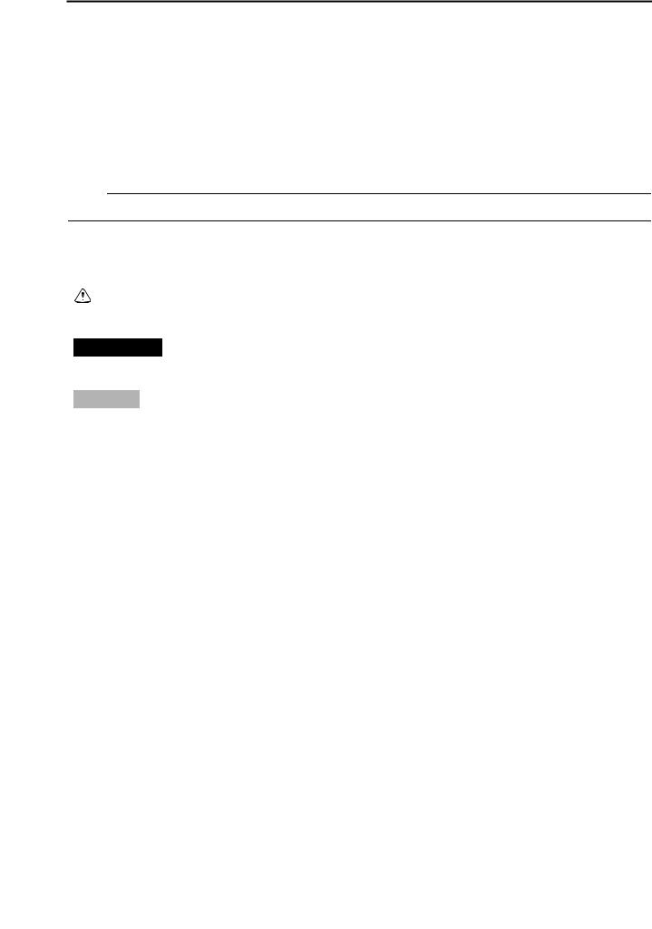
•The manual is divided into chapters and each chapter is divided into sections. The current section title “1” is shown at the top of each page.
•Sub-section titles “2” appear in smaller print than the section title.
•To help identify parts and clarify procedure steps, there are exploded diagrams “3” at the start of each removal and disassembly section.
•Numbers “4” are given in the order of the jobs in the exploded diagram. A number indicates a disassembly step.
•Symbols “5” indicate parts to be lubricated or replaced. Refer to “SYMBOLS”.
•A job instruction chart “6” accompanies the exploded diagram, providing the order of jobs, names of parts, notes in jobs, etc.
•Jobs “7” requiring more information (such as special tools and technical data) are described sequentially.
|
1 |
|
2 |
3 |
7 |
4 |
|
5 |
|
6 |
|
YamahaR125.COM
EAS20100
SYMBOLS
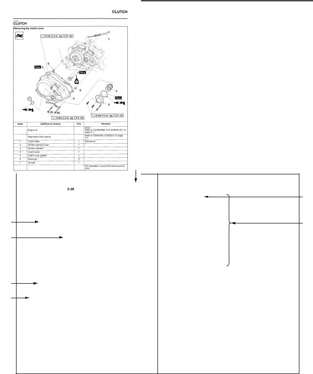
The following symbols are used in this manual for easier understanding.
NOTE:
The following symbols are not relevant to every vehicle.
1 |
2 |
3 |
|
||||
|
|
|
|
|
|
|
|
|
|
|
|
|
|
|
|
|
|
|
|
|
|
|
|
|
|
|
|
|
|
|
|
4 |
5 |
6 |
|
|
T |
|
|
. |
|
|
R |
|
|
. |
7 |
8 |
|
|
|
|
|
|
|
|
|
|
|
|
|
|
|
|
|
|
|
|
|
|
|
|
|
|
|
|
|
|
|
|
|
|
|
|
|
|
|
|
|
|
|
|
|
|
|
|
|
|
|
|
|
|
|
|
|
|
|
|
|
|
|
|
|
|
|
|
|
|
|
|
|
|
|
|
|
|
|
|
|
9 |
|
|
|
|
|
|
10 |
|
|
|
|||||
|
|
|
|
|
|
|
|
|
|
|
|
|
|
|
|
|
E |
|
|
|
|
|
G |
||||||||
11 |
|
|
|
|
|
|
12 |
|
|
|
|||||
|
|
|
|
|
|
|
|
|
|
|
|
|
|
|
|
|
M |
|
|
|
|
|
BF |
||||||||
13 |
|
|
|
|
|
|
14 |
|
|
|
|||||
|
B |
|
|
|
|
|
LS |
||||||||
15 |
|
|
|
|
|
|
16 |
|
|
|
|||||
M |
|
|
|
|
|
S |
|||||||||
17 |
|
|
|
|
|
|
18 |
|
|
|
|||||
LT New
1.Serviceable with engine mounted
2.Filling fluid
3.Lubricant
4.Special tool
5.Tightening torque
6.Wear limit, clearance
7.Engine speed
8.Electrical data
9.Engine oil
10.Gear oil
11.Molybdenum disulfide oil
12.Brake fluid
13.Wheel bearing grease
14.Lithium-soap-based grease
15.Molybdenum disulfide grease
16.Silicone grease
17.Apply locking agent (LOCTITE®).
18.Replace the part with a new one.

YamahaR125.COM
YamahaR125.COM
EAS20110
TABLE OF CONTENTS
GENERAL INFORMATION
SPECIFICATIONS
PERIODIC CHECKS AND
ADJUSTMENTS
CHASSIS
ENGINE
COOLING SYSTEM
FUEL SYSTEM
ELECTRICAL SYSTEM
1
2
3
4
5
6
7
8
TROUBLESHOOTING |
9 |
|
|

YamahaR125.COM

YamahaR125.COM
GENERAL INFORMATION
IDENTIFICATION ............................................................................................ |
1-1 |
|
|
VEHICLE IDENTIFICATION NUMBER |
1-1 |
|
|
|
|||
MODEL LABEL.......................................................................................... |
1-1 |
1 |
|
FEATURES |
1-2 |
||
|
|||
OUTLINE OF THE FI SYSTEM |
1-2 |
|
|
|
|||
FI SYSTEM................................................................................................ |
1-3 |
|
|
MULTI-FUNCTION DISPLAY.................................................................... |
1-4 |
|
|
IMPORTANT INFORMATION ......................................................................... |
1-5 |
|
|
PREPARATION FOR REMOVAL AND DISASSEMBLY........................... |
1-5 |
|
|
REPLACEMENT PARTS........................................................................... |
1-5 |
|
|
GASKETS, OIL SEALS AND O-RINGS .................................................... |
1-5 |
|
|
LOCK WASHERS/PLATES AND COTTER PINS ..................................... |
1-5 |
|
|
BEARINGS AND OIL SEALS .................................................................... |
1-6 |
|
|
CIRCLIPS .................................................................................................. |
1-6 |
|
|
CHECKING THE CONNECTIONS .................................................................. |
1-7 |
|
|
SPECIAL TOOLS ............................................................................................ |
1-8 |
|

YamahaR125.COM IDENTIFICATION
EAS20130
IDENTIFICATION
EAS20140
VEHICLE IDENTIFICATION NUMBER
The vehicle identification number “1” is stamped into the right side of the steering head pipe.
1
EAS20150
MODEL LABEL
The model label “1” is affixed to the frame. This information will be needed to order spare parts.
1
1-1
YamahaR125.COM FEATURES
EAS20170
FEATURES
EAS5D71022
OUTLINE OF THE FI SYSTEM
The main function of a fuel supply system is to provide fuel to the combustion chamber at the optimum air-fuel ratio in accordance with the engine operating conditions and the atmospheric temperature. In the conventional carburetor system, the air-fuel ratio of the mixture that is supplied to the combustion chamber is created by the volume of the intake air and the fuel that is metered by the jet used in the respective carburetor.
Despite the same volume of intake air, the fuel volume requirement varies by the engine operating conditions, such as acceleration, deceleration, or operating under a heavy load. Carburetors that meter the fuel through the use of jets have been provided with various auxiliary devices, so that an optimum airfuel ratio can be achieved to accommodate the constant changes in the operating conditions of the engine.
As the requirements for the engine to deliver more performance and cleaner exhaust gases increase, it becomes necessary to control the air-fuel ratio in a more precise and finely tuned manner. To accommodate this need, this model has adopted an electronically controlled fuel injection (FI) system, in place of the conventional carburetor system. This system can achieve an optimum air-fuel ratio required by the engine at all times by using a microprocessor that regulates the fuel injection volume according to the engine operating conditions detected by various sensors.
The adoption of the FI system has resulted in a highly precise fuel supply, improved engine response, better fuel economy, and reduced exhaust emissions.
1 |
2 |
3 |
4 |
|
|
5,6 |
7 |
8 |
||||
|
|
|
|
|
|
|
|
|
|
|
|
|
|
|
|
|
|
|
|
|
|
|
|
|
|
|
|
|
|
|
|
|
|
|
|
|
|
|
|
|
|
|
|
|
|
|
|
|
|
|
|
|
|
|
|
|
|
|
|
|
|
|
|
|
|
|
|
|
|
|
|
|
|
|
|
|
|
|
|
|
|
|
|
|
|
|
|
|
|
|
|
|
|
|
|
|
|
|
|
|
|
|
|
|
|
|
|
|
|
|
|
|
|
|
|
|
11 10 9
1.Engine trouble warning light
2.Spark plug
3.Ignition coil
4.Fuel pump
5.FID (fast idle solenoid)
6.Throttle body sensor assembly (consisting of throttle position sensor, intake air pressure sensor, intake air temperature sensor)
7.ECU (engine control unit)
8.Lean angle sensor
9.Crankshaft position sensor
10.Fuel injector
11.Coolant temperature sensor
1-2
YamahaR125.COM FEATURES
EAS5D71023
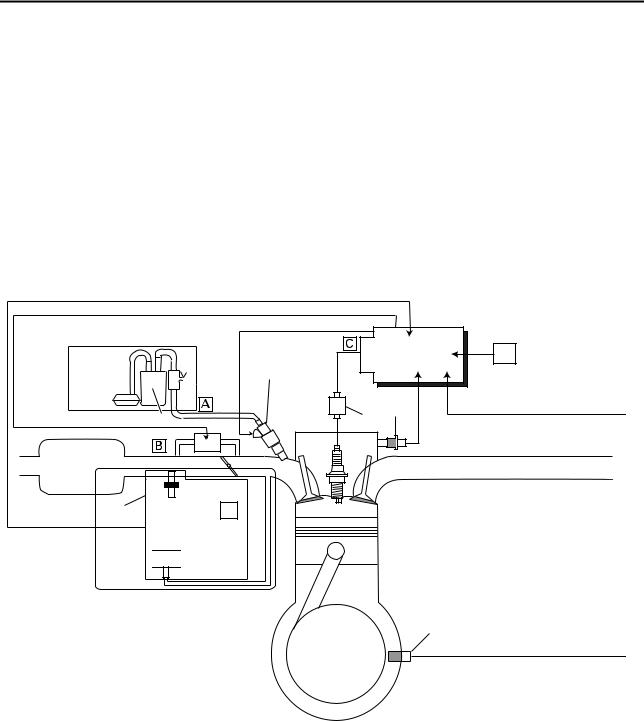
FI SYSTEM
The fuel pump delivers fuel to the fuel injector via the fuel filter. The pressure regulator maintains the fuel pressure that is applied to the fuel injector at only 250 kPa (2.50 kg/cm², 36.3 psi). Accordingly, when the energizing signal from the ECU energizes the fuel injector, the fuel passage opens, causing the fuel to be injected into the intake manifold only during the time the passage remains open. Therefore, the longer the length of time the fuel injector is energized (injection duration), the greater the volume of fuel that is supplied. Conversely, the shorter the length of time the fuel injector is energized (injection duration), the lesser the volume of fuel that is supplied.
The injection duration and the injection timing are controlled by the ECU. Signals that are input from the throttle position sensor, crankshaft position sensor, intake air pressure sensor, intake air temperature sensor, lean angle sensor and coolant temperature sensor enable the ECU to determine the injection duration. The injection timing is determined through the signals from the crankshaft position sensor. As a result, the volume of fuel that is required by the engine can be supplied at all times in accordance with the driving conditions.
|
|
5 |
6 |
|
2 |
|
|
1 |
3 |
4 |
|
|
|
||
8 |
|
|
|
|
|
|
9
11 12
13

 14
14
10
1.Fuel pump
2.Fuel injector
3.Ignition coil
4.Coolant temperature sensor
5.ECU (engine control unit)
6.Lean angle sensor
7.Crankshaft position sensor
8.FID (fast idle solenoid)
9.Air filter case
10.Throttle body
7
11.Throttle body sensor assembly
12.Intake air temperature sensor
13.Throttle position sensor
14.Intake air pressure sensor
A.Fuel system
B.Air system
C.Control system
1-3
YamahaR125.COM FEATURES
EAS5D71046
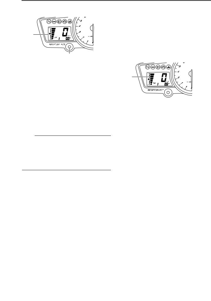
MULTI-FUNCTION DISPLAY
1
2
1.Multi-function display
2.“RESET/SELECT” button
The multi-function display is equipped with the following:
•a speedometer (which shows the riding speed)
•an odometer (which shows the total distance traveled)
•two tripmeters (which show the distance traveled since they were last set to zero)
•a fuel reserve tripmeter (which shows the distance traveled since the fuel level warning light came on)
•a fuel meter
NOTE:
•Be sure to turn the key to “ON” before using the “RESET/ SELECT” button.
•For the U.K. only: To switch the speedometer and odometer/tripmeter displays between kilometers and miles, press the “RESET/SELECT” button for at least eight seconds.
Odometer and tripmeter modes
A brief push (less than one second) on the “RESET/SELECT” button switches the display between the odometer mode “ODO” and the tripmeter modes “TRIP 1” and “TRIP 2” in the following order:
ODO → TRIP 1 → TRIP 2 → ODO
When approximately 1.6 L (0.42 US gal) (0.35 Imp.gal) of fuel remains in the fuel tank, the odometer display will automatically change to the fuel reserve tripmeter mode “F-TRIP” and start counting the distance traveled from that point, and the last segment of the fuel meter will start flashing. In that case, pushing the “RESET/SELECT” button switches the display between the various tripmeter and odometer modes in the following order:
F-TRIP → TRIP 1 → TRIP 2 → ODO → F-TRIP
To reset a tripmeter, select it by pushing the “RESET/SELECT” button briefly (less than one second), and then push the button for at least three seconds while the selected tripmeter is flashing. If you do not reset the fuel reserve tripmeter manually, it will reset itself automatically and the display will return to the prior mode after refueling and traveling 5 km (3 mi).
Fuel meter
1
1. Fuel meter
The fuel meter indicates the amount of fuel in the fuel tank. The display segments of the fuel meter disappear towards “E” (Empty) as the fuel level decreases. When the last fuel meter segment starts flashing, refuel as soon as possible.
1-4

YamahaR125.COM |
IMPORTANT INFORMATION |
|
EAS20180
IMPORTANT INFORMATION
EAS20190
PREPARATION FOR REMOVAL AND
DISASSEMBLY
1.Before removal and disassembly, remove all dirt, mud, dust and foreign material.
2.Use only the proper tools and cleaning equipment.
Refer to “SPECIAL TOOLS” on page 1-8.
3.When disassembling, always keep mated parts together. This includes gears, cylinders, pistons and other parts that have been “mated” through normal wear. Mated parts must always be reused or replaced as an assembly.
4.During disassembly, clean all of the parts and place them in trays in the order of disassembly. This will speed up assembly and allow for the correct installation of all parts.
5.Keep all parts away from any source of fire.
EAS20200
REPLACEMENT PARTS
Use only genuine Yamaha parts for all replacements. Use oil and grease recommended by Yamaha for all lubrication jobs. Other brands may be similar in function and appearance, but inferior in quality.
EAS20210
GASKETS, OIL SEALS AND O-RINGS
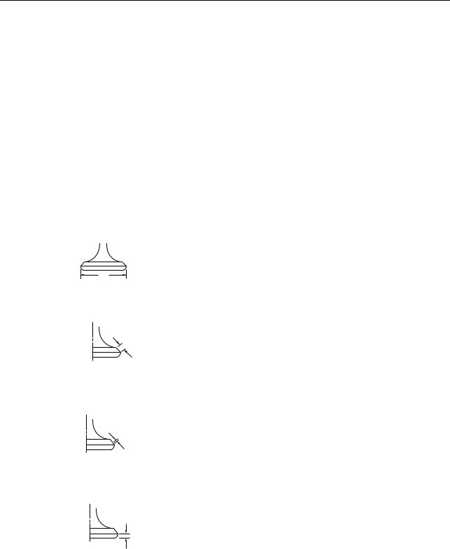
1.When overhauling the engine, replace all gaskets, seals and O-rings. All gasket surfaces, oil seal lips and O-rings must be cleaned.
2.During reassembly, properly oil all mating parts and bearings and lubricate the oil seal lips with grease.
1.Oil
2.Lip
3.Spring
4.Grease
EAS20220
LOCK WASHERS/PLATES AND COTTER PINS
After removal, replace all lock washers/plates “1” and cotter pins. After the bolt or nut has been tightened to specification, bend the lock tabs along a flat of the bolt or nut.
1-5
YamahaR125.COM |
IMPORTANT INFORMATION |
|
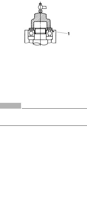
EAS20230
BEARINGS AND OIL SEALS
Install bearings “1” and oil seals “2” so that the manufacturer’s marks or numbers are visible. When installing oil seals “1”, lubricate the oil seal lips with a light coat of lithium-soap-based grease. Oil bearings liberally when installing, if appropriate.
ECA13300
CAUTION:
Do not spin the bearing with compressed air because this will damage the bearing surfaces.
EAS20240
CIRCLIPS
Before reassembly, check all circlips carefully and replace damaged or distorted circlips. Always replace piston pin clips after one use.
When installing a circlip “1”, make sure the sharp-edged corner “2” is positioned opposite the thrust “3” that the circlip receives.
1-6
YamahaR125.COM CHECKING THE CONNECTIONS
EAS20250
CHECKING THE CONNECTIONS
Check the leads, couplers, and connectors for stains, rust, moisture, etc.
1.Disconnect:
•Lead
•Coupler
•Connector
2.Check:
•Lead
•Coupler
•Connector
Moisture → Dry with an air blower. Rust/stains → Connect and disconnect several times.
3.Check:
•All connections
Loose connection → Connect properly.
NOTE:
If the pin “1” on the terminal is flattened, bend it up.
4.Connect:
•Lead
•Coupler
•Connector
NOTE:
Make sure all connections are tight.
5.Check:
•Continuity
(with the pocket tester)
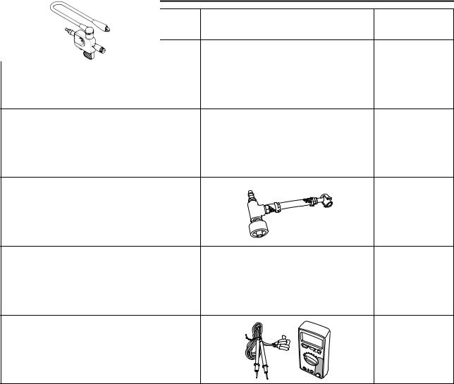
Pocket tester 90890-03112
Analog pocket tester YU-03112-C
NOTE:
•If there is no continuity, clean the terminals.
•When checking the wire harness, perform steps (1) to (3).
•As a quick remedy, use a contact revitalizer available at most part stores.
1-7
YamahaR125.COM |
SPECIAL TOOLS |
|
EAS20260
SPECIAL TOOLS
The following special tools are necessary for complete and accurate tune-up and assembly. Use only the appropriate special tools as this will help prevent damage caused by the use of inappropriate tools or improvised techniques. Special tools, part numbers or both may differ depending on the country.
When placing an order, refer to the list provided below to avoid any mistakes.
NOTE:
•For U.S.A. and Canada, use part number starting with “YM-”, “YU-”, or “ACC-”.
•For others, use part number starting with “90890-”.
Tool name/Tool No. |
Illustration |
|
Reference |
|
pages |
||
|
|
|
|
Pocket tester |
|
|
1-7, 5-36, 8-61, |
90890-03112 |
|
|
8-62, 8-63, |
Analog pocket tester |
|
|
8-66, 8-67, |
YU-03112-C |
|
|
8-68, 8-69, |
|
|
|
8-70, 8-71, |
|
|
|
8-72, 8-73, |
|
|
|
8-74, 8-75 |
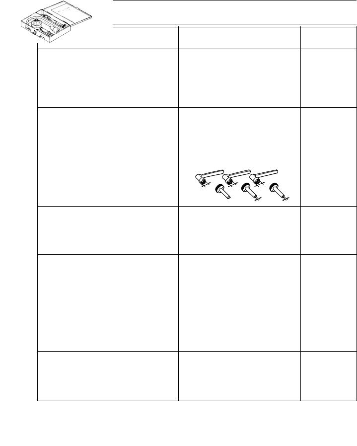
Tappet adjusting tool |
|
|
3-4 |
90890-01311 |
|
|
|
Six piece tappet set |
|
|
|
YM-A5970 |
|
|
|
YM-A5970 |
|
|
|
ø8 |
ø9 |
ø10 |
|
|
|
ø3 |
ø4 |
FI diagnostic tool |
|
|
3-5, 8-35 |
90890-03182 |
|
|
|
Timing light |
3-8 |
90890-03141 |
|
Inductive clamp timing light |
|
YU-03141 |
|
|
|
Extension |
3-9 |
90890-04082 |
|
Compression gauge |
3-9 |
90890-03081 |
|
Engine compression tester |
|
YU-33223 |
|
1-8
YamahaR125.COM |
|
SPECIAL TOOLS |
|
|
|
||
|
|
|
|
Tool name/Tool No. |
Illustration |
Reference |
|
pages |
|||
|
|
||
|
|
|
|
Steering nut wrench |
|
3-22, 4-54 |
|
90890-01403 |
|
|
|
Spanner wrench |
|
|
|
YU-33975 |
|
|
|
|
|
|
|
Damper rod holder |
|
4-48, 4-49 |
|
90890-01294 |
|
|
|
Damping rod holder set |
|
|
|
YM-01300 |
|
|
YM-01300
T-handle |
4-48, 4-49 |
90890-01326 |
|
T-handle 3/8" drive 60 cm long |
|
YM-01326 |
|
|
|
Fork seal driver weight |
4-49, 4-50 |
90890-01367 |
|
Replacement hammer |
|
YM-A9409-7 |
|
YM-A9409-7/YM-A5142-4
Fork seal driver attachment (ø33) |
4-49 |
90890-01368 |
|
Replacement 33 mm |
|
YM-A9409-4 |
|
|
|
Yamaha bond No. 1215 |
5-12, 5-33, |
90890-85505 |
5-60 |
(Three Bond No.1215®) |
|
1-9
YamahaR125.COM |
|
SPECIAL TOOLS |
||
|
|
|
||
|
|
|
|
|
Tool name/Tool No. |
|
Illustration |
|
Reference |
|
|
pages |
||
|
|
|
|
|
|
|
|
|
|
Valve spring compressor |
|
|
|
5-18, 5-23 |
90890-04019 |
|
|
|
|
YM-04019 |
|
|
|
|
|
|
|
|
|
Valve spring compressor attachment |
|
|
|
5-18, 5-23 |
90890-04108 |
|
|
|
|
Valve spring compressor adapter 22 mm |
|
|
|
|
YM-04108 |
|
|
|
|
|
|
|
|
|
Valve guide remover (ø4.5) |
|
|
|
5-19 |
90890-04116 |
|
|
|
|
Valve guide remover (4.5 mm) |
|
|
|
|
YM-04116 |
|
|
|
|
|
|
|
|
|
Valve guide installer (ø4.5) |
|
|
|
5-19 |
90890-04117 |
|
|
|
|
Valve guide installer (4.5 mm) |
|
|
|
|
YM-04117 |
|
|
|
|
|
|
|
|
|
Valve guide reamer (ø4.5) |
|
|
|
5-19 |
90890-04118 |
|
|
|
|
Valve guide reamer (4.5 mm) |
|
|
|
|
YM-04118 |
|
|
|
|
|
|
|
|
|
Piston pin puller set |
|
|
|
5-25 |
90890-01304 |
|
|
|
|
Piston pin puller |
|
|
|
|
YU-01304 |
|
|
|
|
|
YU-01304 |
|
|
|
|
|
|
|
|
Sheave holder |
|
|
|
5-31, 5-32, |
90890-01701 |
|
|
|
5-33 |
Primary clutch holder |
|
|
|
|
YS-01880-A |
|
|
|
|
|
|
|
|
|
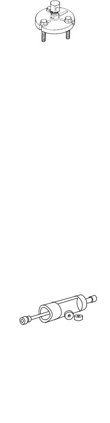
Flywheel puller |
|
|
|
5-31 |
90890-01362 |
|
|
|
|
Heavy duty puller |
|
|
|
|
YU-33270-B |
|
|
|
|
|
|
|
|
|
1-10
YamahaR125.COM |
|
SPECIAL TOOLS |
|
|
|
||
|
|
|
|
Tool name/Tool No. |
Illustration |
Reference |
|
pages |
|||
|
|
||
|
|
|
|
Universal clutch holder |
|
5-42, 5-44 |
|
90890-04086 |
|
|
|
YM-91042 |
|
|
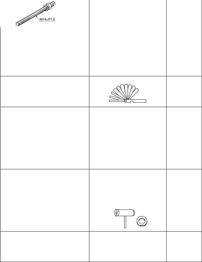
Thickness gauge |
5-42 |
90890-03180 |
|
Feeler gauge set |
|
YU-26900-9 |
|
Crankcase separating tool |
5-62 |
90890-01135 |
|
Crankcase separator |
|
YU-01135-B |
|
Crankshaft installer pot |
5-63 |
90890-01274 |
|
Installing pot |
|
YU-90058 |
|
YU-90058/YU-90059
Crankshaft installer bolt |
5-63 |
90890-01275 |
|
Bolt |
|
YU-90060 |
|
1-11
YamahaR125.COM |
|
SPECIAL TOOLS |
|
|
|
||
Tool name/Tool No. |
Illustration |
Reference |
|
pages |
|||
|
|
||
Adapter (M12) |
|
5-63 |
|
90890-01278 |
|
|
|
Adapter #3 |
|
|
|
YU-90063 |
|
|
|
Spacer (crankshaft installer) |
|
5-63 |
|
90890-04081 |
|
|
|
Pot spacer |
|
|
|
YM-91044 |
|
|
|
YM-91044 |
|
|
|
Radiator cap tester |
|
6-3 |
|
90890-01325 |
|
|
|
Radiator pressure tester |
|
|
|
YU-24460-01 |
|
|
|
YU-24460-01 |
|
|
|
Radiator cap tester adapter |
|
6-3 |
|
90890-01352 |
|
|
|
Radiator pressure tester adapter |
|
|
|
YU-33984 |
|
|
|
YU-33984 |
|
|
|
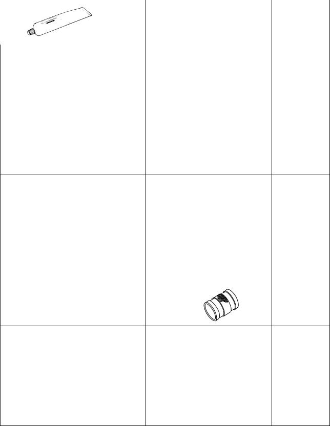
Mechanical seal installer |
|
6-8 |
|
90890-04145 |
|
|
1-12
YamahaR125.COM |
|
SPECIAL TOOLS |
|
|
|
||
Tool name/Tool No. |
Illustration |
Reference |
|
pages |
|||
|
|
||
Middle driven shaft bearing driver |
|
6-8 |
|
90890-04058 |
|
|
|
Bearing driver 40 mm |
|
|
|
YM-04058 |
|
|
|
Pressure gauge |
|
7-3 |
|
90890-03153 |
|
|
|
YU-03153 |
|
|
|
Fuel pressure adapter |
|
7-3 |
|
90890-03181 |
|
|
|
Ignition checker |
|
8-69 |
|
90890-06754 |
|
|
|
Opama pet-4000 spark checker |
|
|
|
YM-34487 |
|
|
|
Digital circuit tester |
|
8-73 |
|
90890-03174 |
|
|
|
Model 88 Multimeter with tachometer |
|
|
|
YU-A1927 |
|
|
1-13

YamahaR125.COM
SPECIFICATIONS
GENERAL SPECIFICATIONS ........................................................................ |
2-1 |
|
ENGINE SPECIFICATIONS ............................................................................ |
2-2 |
|
CHASSIS SPECIFICATIONS .......................................................................... |
2-9 |
|
|
|
|
ELECTRICAL SPECIFICATIONS |
2-12 |
2 |
|
||
TIGHTENING TORQUES .............................................................................. |
2-15 |
|
.........................GENERAL TIGHTENING TORQUE SPECIFICATIONS |
2-15 |
|
ENGINE TIGHTENING TORQUES......................................................... |
2-16 |
|
CHASSIS TIGHTENING TORQUES....................................................... |
2-19 |
|
LUBRICATION POINTS AND LUBRICANT TYPES .................................... |
2-22 |
|
ENGINE................................................................................................... |
2-22 |
|
CHASSIS................................................................................................. |
2-24 |
|
LUBRICATION SYSTEM CHART AND DIAGRAMS.................................... |
2-25 |
|
ENGINE OIL LUBRICATION CHART ..................................................... |
2-25 |
|
LUBRICATION DIAGRAMS .................................................................... |
2-27 |
|
COOLING SYSTEM DIAGRAMS .................................................................. |
2-31 |
|
CABLE ROUTING ......................................................................................... |
2-33 |
|
YamahaR125.COM |
GENERAL SPECIFICATIONS |
|
|
EAS20280 |
|
GENERAL SPECIFICATIONS |
|
|
|
Model |
|
Model |
5D71 (Europe) |
|
|
Dimensions |
|
Overall length |
2015 mm (79.3 in) |
Overall width |
660 mm (26.0 in) |
Overall height |
1065 mm (41.9 in) |
Seat height |
818 mm (32.2 in) |
Wheelbase |
1355 mm (53.3 in) |
Ground clearance |
155 mm (6.10 in) |
Minimum turning radius |
3100 mm (122.0 in) |
|
|
Weight |
|
With oil and fuel |
138.0 kg (304 lb) |
Maximum load |
185 kg (408 lb) |
2-1

YamahaR125.COM
ENGINE SPECIFICATIONS
EAS20290
ENGINE SPECIFICATIONS
Engine
Engine type Displacement Cylinder arrangement Bore × stroke Compression ratio
Standard compression pressure (at sea level)
Minimum–maximum
Starting system
Liquid cooled 4-stroke, SOHC 124.7 cm³
Forward-inclined single cylinder
52.0× 58.6 mm (2.05 × 2.31 in)
11.20:1
550 kPa/600 r/min (78.2 psi/600 r/min) (5.5 kgf/cm²/600 r/min)
480–620 kPa (68.3–88.2 psi) (4.8–6.2 kgf/cm²) Electric starter
Fuel |
|
|
Recommended fuel |
Premium unleaded gasoline only |
|
Fuel tank capacity |
13.8 |
L (3.65 US gal) (3.04 Imp.gal) |
Fuel reserve amount |
1.6 L (0.42 US gal) (0.35 Imp.gal) |
|
|
|
|
Engine oil |
|
|
Lubrication system |
Wet sump |
|
Type |
SAE 10W-30, SAE 10W-40, SAE 15W-40, SAE |
|
|
20W-40 or SAE 20W-50 |
|
Recommended engine oil grade |
API service SG type or higher, JASO standard |
|
|
MA |
|
Engine oil quantity |
|
|
Total amount |
1.15 |
L (1.22 US qt) (1.01 Imp.qt) |
Without oil filter element replacement |
0.95 |
L (1.00 US qt) (0.84 Imp.qt) |
With oil filter element replacement |
1.00 |
L (1.06 US qt) (0.88 Imp.qt) |
|
|
|
Oil filter |
|
|
Oil filter type |
Paper |
|
Oil pump
Oil pump type Inner-rotor-to-outer-rotor-tip clearance Limit
Outer-rotor-to-oil-pump-housing clearance Limit Oil-pump-housing-to-inner-and-outer-rotor
clearance Limit
Relief valve operating pressure
Pressure check location
Trochoid
Less than 0.15 mm (0.0059 in) 0.23 mm (0.0091 in)
0.13–0.18 mm (0.0051–0.0071 in) 0.25 mm (0.0098 in)
0.06–0.11 mm (0.0024–0.0043 in) 0.18 mm (0.0071 in)
39.2–78.4 kPa (5.7–11.4 psi) (0.39–0.78 kgf/cm²)
Check bolt on cylinder head body
Cooling system |
|
Radiator capacity (including all routes) |
1.00 L (1.06 US qt) (0.88 Imp.qt) |
Coolant reservoir capacity (up to the maximum level |
|
mark) |
0.25 L (0.26 US qt) (0.22 Imp.qt) |
Radiator cap opening pressure |
107.9 – 137.3 kPa (15.6–19.9 psi) (1.08–1.37 |
|
kgf/cm²) |
2-2
YamahaR125.COM
ENGINE SPECIFICATIONS
Thermostat |
|
Model/manufacturer |
5YP/NIPPON THERMOSTAT |
Valve opening temperature |
80.5–83.5 °C (176.9–182.3 °F) |
Valve full open temperature |
95.0 °C (203.0 °F) |
Valve lift (full open) |
3.0 mm (0.12 in) |
Radiator core |
|
Width |
198.0 mm (7.80 in) |
Height |
128.0 mm (5.04 in) |
Depth |
24.0 mm (0.94 in) |
Water pump |
|
Water pump type |
Single suction centrifugal pump |
Reduction ratio |
19/38 (0.500) |
|
|
Spark plug (s) |
|
Manufacturer/model |
NGK/CR8E |
Spark plug gap |
0.7–0.8 mm (0.028–0.031 in) |
|
|
Cylinder head |
|
Volume |
9.90–10.50 cm³ (0.60–0.64 cu.in) |
Warpage limit |
0.03 mm (0.0012 in) |
Camshaft |
|
||
Drive system |
Chain drive (left) |
||
Camshaft lobe dimensions |
|
||
Intake A |
30.225–30.325 mm (1.1900–1.1939 in) |
||
Limit |
30.125 mm (1.1860 in) |
||
Intake B |
25.127–25.227 mm (0.9893–0.9932 in) |
||
Limit |
25.027 mm (0.9853 in) |
||
Exhaust A |
30.232–30.332 mm (1.1902–1.1942 in) |
||
Limit |
30.132 mm (1.1863 in) |
||
Exhaust B |
25.065–25.165 mm (0.9868–0.9907 in) |
||
Limit |
24.965 mm (0.9829 in) |
||
|
|
|
|
|
|
|
|
A
B
Camshaft runout limit |
0.030 mm (0.0012 in) |
2-3
YamahaR125.COM
ENGINE SPECIFICATIONS
Timing chain |
|
Model/number of links |
DID SCR-0404SV/96 |
Tensioning system |
Automatic |
|
|
Rocker arm/rocker arm shaft |
|
Rocker arm inside diameter |
9.985–10.000 mm (0.3931–0.3937 in) |
Limit |
10.015 mm (0.3943 in) |
Rocker arm shaft outside diameter |
9.966–9.976 mm (0.3924–0.3928 in) |
Limit |
9.941 mm (0.3914 in) |
Rocker-arm-to-rocker-arm-shaft clearance |
0.009–0.034 mm (0.0004–0.0013 in) |
Limit |
0.074 mm (0.0029 in) |
|
|
Valve, valve seat, valve guide |
|
Valve clearance (cold) |
|
Intake |
0.10–0.14 mm (0.0039–0.0055 in) |
Exhaust |
0.20–0.24 mm (0.0079–0.0094 in) |
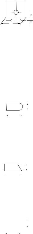
Valve dimensions |
|
Valve head diameter A (intake) |
19.40–19.60 mm (0.7638–0.7717 in) |
Valve head diameter A (exhaust) |
16.90–17.10 mm (0.6654–0.6732 in) |
A
Valve face width B (intake) |
1.538–2.138 mm (0.0606–0.0842 in) |
Valve face width B (exhaust) |
1.538–2.138 mm (0.0606–0.0842 in) |
B |
|
Valve seat width C (intake) |
0.90–1.10 mm (0.0354–0.0433 in) |
Limit |
1.6 mm (0.06 in) |
Valve seat width C (exhaust) |
0.90–1.10 mm (0.0354–0.0433 in) |
C |
|
Limit |
1.6 mm (0.06 in) |
Valve margin thickness D (intake) |
0.50–0.90 mm (0.0197–0.0354 in) |
Valve margin thickness D (exhaust) |
0.50–0.90 mm (0.0197–0.0354 in) |
D |
|
Valve stem diameter (intake) |
4.475–4.490 mm (0.1762–0.1768 in) |
Limit |
4.445 mm (0.1750 in) |
Valve stem diameter (exhaust) |
4.460–4.475 mm (0.1756–0.1762 in) |
Limit |
4.430 mm (0.1744 in) |
Valve guide inside diameter (intake) |
4.500–4.512 mm (0.1772–0.1776 in) |
Limit |
4.550 mm (0.1791 in) |
Valve guide inside diameter (exhaust) |
4.500–4.512 mm (0.1772–0.1776 in) |
2-4

YamahaR125.COM
ENGINE SPECIFICATIONS
Limit |
4.550 mm (0.1791 in) |
||||||||||||||
Valve-stem-to-valve-guide clearance (intake) |
0.010–0.037 mm (0.0004–0.0015 in) |
||||||||||||||
Limit |
0.080 mm (0.0032 in) |
||||||||||||||
Valve-stem-to-valve-guide clearance (exhaust) |
0.025–0.052 mm (0.0010–0.0020 in) |
||||||||||||||
Limit |
0.100 mm (0.0039 in) |
||||||||||||||
Valve stem runout |
0.010 mm (0.0004 in) |
||||||||||||||
|
|
|
|
|
|
|
|
|
|
|
|
|
|
|
|
|
|
|
|
|
|
|
|
|
|
|
|
|
|
|
|
|
|
|
|
|
|
|
|
|
|
|
|
|
|
|
|
|
|
|
|
|
|
|
|
|
|
|
|
|
|
|
|
|
|
|
|
|
|
|
|
|
|
|
|
|
|
|
|
|
|
|
|
|
|
|
|
|
|
|
|
|
|
|
|
Cylinder head valve seat width (intake) |
0.90–1.10 mm (0.0354–0.0433 in) |
Limit |
1.6 mm (0.06 in) |
Cylinder head valve seat width (exhaust) |
0.90–1.10 mm (0.0354–0.0433 in) |
Limit |
1.6 mm (0.06 in) |
Valve spring
Free length (intake) Limit
Free length (exhaust) Limit
Installed length (intake) Installed length (exhaust) Spring rate K1 (intake) Spring rate K2 (intake) Spring rate K1 (exhaust) Spring rate K2 (exhaust)
Installed compression spring force (intake) Installed compression spring force (exhaust) Spring tilt (intake)
Spring tilt (exhaust)
Winding direction (intake)
Winding direction (exhaust)
41.71mm (1.64 in)
39.62mm (1.56 in)
41.71mm (1.64 in)
39.62mm (1.56 in)
35.30mm (1.39 in)
35.30mm (1.39 in)
23.54N/mm (134.41 lb/in) (2.40 kgf/mm)
36.58N/mm (208.87 lb/in) (3.73 kgf/mm)
23.54N/mm (134.41 lb/in) (2.40 kgf/mm)
36.58N/mm (208.87 lb/in) (3.73 kgf/mm) 140–162 N (31.47–36.42 lbf) (14.28–16.52 kgf) 140–162 N (31.47–36.42 lbf) (14.28–16.52 kgf) 2.5°/1.8 mm
2.5°/1.8 mm
Clockwise
Clockwise
Cylinder |
|
Bore |
52.000–52.010 mm (2.0472–2.0476 in) |
Wear limit |
52.110 mm (2.0516 in) |
Taper limit |
0.050 mm (0.0020 in) |
Out of round limit |
0.005 mm (0.0002 in) |
|
|
Piston |
|
Piston-to-cylinder clearance |
0.015–0.048 mm (0.0006–0.0019 in) |
Limit |
0.15 mm (0.0059 in) |
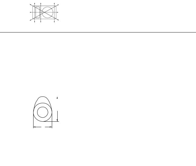
Diameter D |
51.962–51.985 mm (2.0457–2.0466 in) |
2-5
YamahaR125.COM
ENGINE SPECIFICATIONS
Height H |
|
5.0 mm (0.20 in) |
|
|
|
|
|
|
|
|
|
H
D
Offset |
0.50 mm (0.0197 in) |
||||||||||||
Offset direction |
Intake side |
||||||||||||
Piston pin bore inside diameter |
14.002–14.013 mm (0.5513–0.5517 in) |
||||||||||||
Limit |
14.043 mm (0.5529 in) |
||||||||||||
Piston pin outside diameter |
13.995–14.000 mm (0.5510–0.5512 in) |
||||||||||||
Limit |
13.975 mm (0.5502 in) |
||||||||||||
Piston-pin-to-piston-pin-bore clearance |
0.002–0.018 mm (0.0001–0.0007 in) |
||||||||||||
Limit |
0.068 mm (0.0027 in) |
||||||||||||
|
|
|
|
|
|
|
|
|
|
|
|
|
|
Piston ring |
|
||||||||||||
Top ring |
|
||||||||||||
Ring type |
Barrel |
||||||||||||
Dimensions (B × T) |
0.80 × 1.90 mm (0.03 × 0.07 in) |
||||||||||||
|
|
|
|
|
|
|
|
|
|
|
|
|
|
|
|
|
|
|
|
|
|
|
|
|
B |
|
|
|
|
|
|
T |
|
|
|
|
|
|
|
||
|
|
|
|
|
|
|
|
|
|
||||
|
|
|
|
|
|
|
|
|
|
|
|
|
|
End gap (installed) |
0.10–0.25 mm (0.0039–0.0098 in) |
||||||||||||
Limit |
0.50 mm (0.0197 in) |
||||||||||||
Ring side clearance |
0.030–0.065 mm (0.0012–0.0026 in) |
||||||||||||
Limit |
0.100 mm (0.0039 in) |
||||||||||||
2nd ring |
|
||||||||||||
Ring type |
Taper |
||||||||||||
Dimensions (B × T) |
0.80 × 2.10 mm (0.03 × 0.08 in) |
||||||||||||
|
|
|
|
|
|
|
|
|
|
|
|
|
|
|
|
|
|
|
|
|
|
|
|
B |
|
||
|
|
|
|
|
|
|
|
|
|
|
|||
|
|
|
|
|
|
|
|
|
|
||||
|
|
|
|
T |
|
|
|
|
|||||
End gap (installed) |
0.10–0.25 mm (0.0039–0.0098 in) |
||||||||||||
Limit |
0.60 mm (0.0236 in) |
||||||||||||
Ring side clearance |
0.020–0.055 mm (0.0008–0.0022 in) |
||||||||||||
Limit |
0.100 mm (0.0039 in) |
||||||||||||
Oil ring |
|
||||||||||||
Dimensions (B × T) |
1.50 × 1.95 mm (0.06 × 0.08 in) |
||||||||||||
|
|
|
|
|
|
|
|
|
|
|
|
|
|
|
|
|
|
|
|
|
|
|
|
B |
|
||
|
|
|
|
|
|
|
|
|
|
|
|||
|
|
|
|
|
|
|
|
|
|
|
|||
|
|
|
|
|
|
|
|
|
|
|
|
|
|
|
|
|
|
|
|
|
|||||||
|
|
|
|
T |
|
|
|||||||
|
|
|
|
|
|
|
|
|
|
|
|
|
|
End gap (installed) |
0.20–0.70 mm (0.0079–0.0276 in) |
||||||||||||
Ring side clearance |
0.040–0.160 mm (0.0016–0.0063 in) |
||||||||||||
|
|
|
|
|
|
|
|
|
|
|
|
|
|
Crankshaft |
|
||||||||||||
Width A |
47.95–48.00 mm (1.888–1.890 in) |
||||||||||||
2-6
YamahaR125.COM
ENGINE SPECIFICATIONS
Runout limit C |
|
|
0.030 mm (0.0012 in) |
||||||||||
Big end side clearance D |
0.110–0.410 mm (0.0043–0.0161 in) |
||||||||||||
Big end radial clearance E |
0.004–0.014 mm (0.0002–0.0006 in) |
||||||||||||
C |
C |
|
|||||||||||
|
|
|
|
|
|
|
|
E |
|
|
|
|
|
|
|
|
|
|
|
|
|
|
|
D |
|
||
|
|
|
|
|
|
|
|
|
|
|
|||
|
|
|
|
|
|
|
|
|
|
|
|
||
|
|
|
|
|
|
|
|
|
|
|
|
||
|
|
|
|
|
|
|
|
|
|
|
|
||
|
|
|
|
|
|
|
|
|
|
|
|
|
|
|
|
|
|
|
A |
|
|
|
|||||
|
|
|
|
|
|
|
|
|
|
|
|
|
|
Balancer |
|
|
|
||||||||||
Balancer drive method |
|
|
Gear |
||||||||||
|
|
|
|
|
|
|
|
|
|
|
|
|
|
Clutch |
|
|
|
||||||||||
Clutch type |
|
|
Wet, multiple-disc |
||||||||||
Clutch release method |
|
|
Inner push, cam push |
||||||||||
Clutch lever free play |
|
|
10.0–15.0 mm (0.39–0.59 in) |
||||||||||
Friction plate 1 thickness |
2.90–3.10 mm (0.114–0.122 in) |
||||||||||||
Wear limit |
|
|
2.80 mm (0.1102 in) |
||||||||||
Plate quantity |
|
|
1 pc |
||||||||||
Friction plate 3 thickness |
2.90–3.10 mm (0.114–0.122 in) |
||||||||||||
Wear limit |
|
|
2.80 mm (0.1102 in) |
||||||||||
Plate quantity |
|
|
3 pcs |
||||||||||
Friction plate 2 thickness |
2.90–3.10 mm (0.114–0.122 in) |
||||||||||||
Wear limit |
|
|
2.80 mm (0.1102 in) |
||||||||||
Plate quantity |
|
|
1 pc |
||||||||||
Clutch plate thickness |
|
|
1.45–1.75 mm (0.057–0.069 in) |
||||||||||
Plate quantity |
|
|
4 pcs |
||||||||||
Warpage limit |
|
|
0.20 mm (0.0079 in) |
||||||||||
Clutch spring free length |
38.71 mm (1.52 in) |
||||||||||||
Minimum length |
|
|
36.77 mm (1.45 in) |
||||||||||
Spring quantity |
|
|
4 pcs |
||||||||||
Push rod bending limit |
|
|
0.500 mm (0.0197 in) |
||||||||||
|
|
|
|
|
|
|
|
|
|
|
|
|
|
Transmission |
|
|
|
||||||||||
Transmission type |
|
|
Constant mesh 6-speed |
||||||||||
Primary reduction system |
Helical gear |
||||||||||||
Primary reduction ratio |
|
|
73/24 (3.042) |
||||||||||
Secondary reduction system |
Chain drive |
||||||||||||
Secondary reduction ratio |
48/14 (3.429) |
||||||||||||
Operation |
|
|
Left foot operation |
||||||||||
Gear ratio |
|
|
|
||||||||||
1st |
|
|
34/12 (2.833) |
||||||||||
2nd |
|
|
30/16 (1.875) |
||||||||||
3rd |
|
|
30/22 (1.364) |
||||||||||
4th |
|
|
24/21 (1.143) |
||||||||||
5th |
|
|
22/23 (0.957) |
||||||||||
6th |
|
|
21/25 (0.840) |
||||||||||
Main axle runout limit |
|
|
0.08 mm (0.0032 in) |
||||||||||
Drive axle runout limit |
|
|
0.08 mm (0.0032 in) |
||||||||||
2-7
 Loading...