


CHROMATIC TUNER
YT-250
YT-250
ついて
|
→ |
|
重傷を負う危険の恐れがある
ている以外のことは、絶対にしないでください。 必ずサービスセンターに相談してください。
所、暖房機器の近く、発熱する機器の上など
や湿度の高い場所
いでください。火災、感電の原因となります。

て、決められた場所に捨て ましょう。
にしてください。間違えま すと電池の破裂や液もれ によって、けがや周囲を汚 損する原因となることが あります。
■
w
q |
y |
 u POWER
 i OUTPUT
 o INPUT
t NOTE r PITCH
eMODE
AUTOMANL. MODE eq AUTO MANL.
NOTE t
● AUTO
1. INPUT oOUTPUT i ON/OFF
INPUT o y
4y
2.POWER u ONq A4=440Hz 2q AUTO
3.PITCH r “”
q w
4-1.
4-2. w LED
E |
|
|
AUTO |
LED OK
■
|
|
|
|
|
|
|
|
|
|
|
|
|
|
|
|
|
|
|
||
1 |
||
YT-250 6F22 006P |
|
|
|
|
をOFF
|
|
|
|
||
|
||
|
||
|
||
|
||
|
||
|
|
|
|
|
|
|
|
|
|
|
|
|
||
|
|
|
|
|
|
|
|
■
|
3 LED |
|
C, D, E, F, G, A, B, # |
|
A0 (27Hz) C8 (4186Hz) |
|
±1 |
|
±3 |
|
A4=435 446Hz 1Hz |
|
INPUT 6φ |
|
OUTPUT 6φ |
|
6F22(006P)9V ×1 |
|
50 AUTO |
|
118 W ×63 H ×24.5 D mm |
|
130g |
|
6F22 9V ×1 |
● MANL.
1.1 3
2.NOTE tq MANL.
3.4
4.2, 3
1.POWER u ON 440Hz
2.PITCH r 435 446Hz
3.PITCH r 2
 435→436→437→438→439→440→441→442→443→444→445→ 446
POWER u OFF 440Hz
|
|
|
|
|
|
|
|
|
(6F22, 006P 9V |
||
|
|
|
POWER u |
|
|
OFF |
|
|
, |
6F22, 006P |
|
|
||
9V |
||
|
■
■ |
|
|
|
|
● |
|
064-8543 |
10 1 1-50 |
TEL. 011-512-6108 |
|
|
984-0015 |
5-7 3F |
TEL. 022-236-0249 |
||
|
|||||
|
211-0025 |
1184 |
TEL. 044-434-3100 |
||
|
|
108-8568 |
2-17-11 |
TEL. 03-5488-6625 |
|
|
|
|
|
|
|
● |
|
435-0048 |
911 |
TEL. 053-465-6711 |
|
1 |
|
454-0058 |
2-1-2 3F TEL. 052-652-2230 |
||
● |
|
565-0803 |
1-16 |
TEL. 06-877-5262 |
|
|
760-0029 |
8-7 |
TEL. 087-822-3045 |
||
|
|||||
|
731-0113 |
6-14-14 |
TEL. 082-874-3787 |
||
|
|||||
|
812-8508 |
2-11-4 |
TEL. 092-472-2134 |
||
● |
|||||
435-0048 |
911 |
TEL. 053-465-1158 |
|||
|
|
|
|
|
|
|
|
|
|
|
|
|
|
|
|
||
|
|
|
|
||
|
|
430-8650 |
10 1 |
TEL. 053-460-2433 |
|
|
|||||
|
EM |
064-8543 |
10 1 1-50 ( ) |
TEL. 011-512-6113 |
|
|
EM |
980-0804 |
2-2-10 |
TEL. 022-222-6147 |
|
|
EM |
108-8568 |
2-17-11 |
TEL. 03-5488-5471 |
|
EM |
108-8568 |
2-17-11 |
TEL. 03-5488-5447 |
||
430-8650 10 1 |
EM |
460-8588 |
1-18-28 |
TEL. 052-201-5199 |
|
EM |
542-0081 |
3-12-9 |
TEL. 06-252-5231 |
||
TEL 053-460-2433 |
EM |
730-8628 |
1-1-18 |
TEL. 082-244-3749 |
|
|
EM |
812-8508 |
2-11-4 |
TEL. 092-472-2130 |
|

CHROMATIC TUNER
YT-250
OWNER’S MANUAL
Thank you for purchasing the YAMAHA YT-250 Chromatic Auto Tuner.
Please read this manual thoroughly and keep it in a safe place for future reference.
■PRECAUTIONS
To prevent damage, do not use the tuner in the following locations:
•places where the unit will be in direct sunlight;
•places subject to temperature and humidity extremes;
•places that are sandy or dusty.
To power the tuner, use only a 6F22 or 006P 9V dry cell battery.
For maximum battery life, always be sure the tuner is turned OFF when not in use.
If an exhausted battery is left in the unit for an extended period of time, it may leak and cause malfunctioning of the unit. When the battery becomes exhausted, always remove it and replace it as soon as possible.
Do not subject the tuner to strong physical shock or vibration. Do not use excessive force on any of the controls.
Never use solvents such as benzene or thinner to clean the tuner. Wipe clean with a soft, dry cloth.
After reading the owner's manual, keep it in a safe place for future reference.
Never dispose of used batteries by burning them. Also make sure to keep batteries away from children.
■ BATTERY REPLACEMENT
When battery power runs down, the
LCD indicator will grow dim. |
Battery cover |
|
|
||
Continued use of the tuner may result in |
|
|
inaccurate operation. Replace the |
Bottom side |
|
battery with a new one (6F22 or 006P |
||
|
||
9V dry cell battery) as soon as possible. |
|
The battery compartment is in the rear of the tuner. Remove the old battery and replace it with a new one of the
same type. Be careful to connect the 6F22 or 006P 9V dry cell battery
battery in the correct polarity.
*Always turn the POWER switch u to “OFF” before changing the battery.
■SPECIFICATIONS
Indicators |
: Liquid crystal display, Tuning guides |
||
Tuning Notes |
: C, D, E, F, G, A, B, # |
||
Note Setting Range |
: A0 (27Hz) – C8 (4186Hz) |
||
Accuracy |
: ±1 cent |
|
|
In Pitch Accuracy |
: ±3 cent |
|
|
Standard Pitch Setting Range |
: A4=435 – 446Hz (1Hz steps) |
||
Input |
: INPUT (6 |
monaural), microphone |
|
Output |
: OUTPUT (6 |
monaural) |
|
Power Source |
: |
9V dry cell battery (006P or 6F22) |
|
Battery Life |
: Approximately 50 hrs. (AUTO mode) |
||
Dimensions (W x H x D) |
: |
118 x 63 x 24.5 mm (4.6" x 2.5" x 1.0") |
|
Weight (including battery) |
: |
130 g (4.6 oz) |
|
Accessory |
: |
9V dry cell battery (6F22) x 1 |
|
*Specifications and external appearance are subject to change without notice.
■TILT SLIT
The tuner can be tilted back by using the slit in the rear panel. Insert a coin or similar flat object into the slit and tilt back as shown in the diagram below.
FCC INFORMATION (U.S.A.)
1.IMPORTANT NOTICE: DO NOT MODIFY THIS UNIT!
This product, when installed as indicated in the instructions contained in this manual, meets FCC requirements. Modifications not expressly approved by Yamaha may void your authority, granted by the FCC, to use the product.
2.IMPORTANT: When connecting this product to accessories and/or another product use only high quality shielded cables. Cable/s supplied with this product MUST be used. Follow all installation instructions. Failure to follow instructions could void your FCC authorization to use this product in the USA.
3.NOTE: This product has been tested and found to comply with the requirements listed in FCC Regulations, Part 15 for Class ”B” digital devices. Compliance with these requirements provides a reasonable level of assurance that your use of this product in a residential environment will not result in harmful interference with other electronic devices. This equipment generates/uses radio frequencies and, if not installed and used according to the instructions found in the users manual, may cause interference harmful to the operation of other electronic devices. Compliance with FCC regulations does not guarantee that interference will not occur in all installations. If this product is found to be the source of interference, which can be determined by turning the unit ”OFF” and ”ON”, please try to eliminate the problem by using one of the following measures:
Relocate either this product or the device that is being affected by the interference.
Utilize power outlets that are on different branch (circuit breaker or fuse) circuits or install AC line filter/s.
In the case of radio or TV interference, relocate/reorient the antenna. If the antenna lead-in is 300 ohm ribbon lead, change the lead-in to co-axial type cable.
If these corrective measures do not produce satisfactory results, please contact the local retailer authorized to distribute this type of product. If you can not locate the appropriate, please contact Yamaha Corporation of America, Electronic Service Division, 6600 Orangethorpe Ave, Buena Park, CA 90620
The above statements apply ONLY to those products distributed by Yamaha Corporations of America or its subsidiaries.
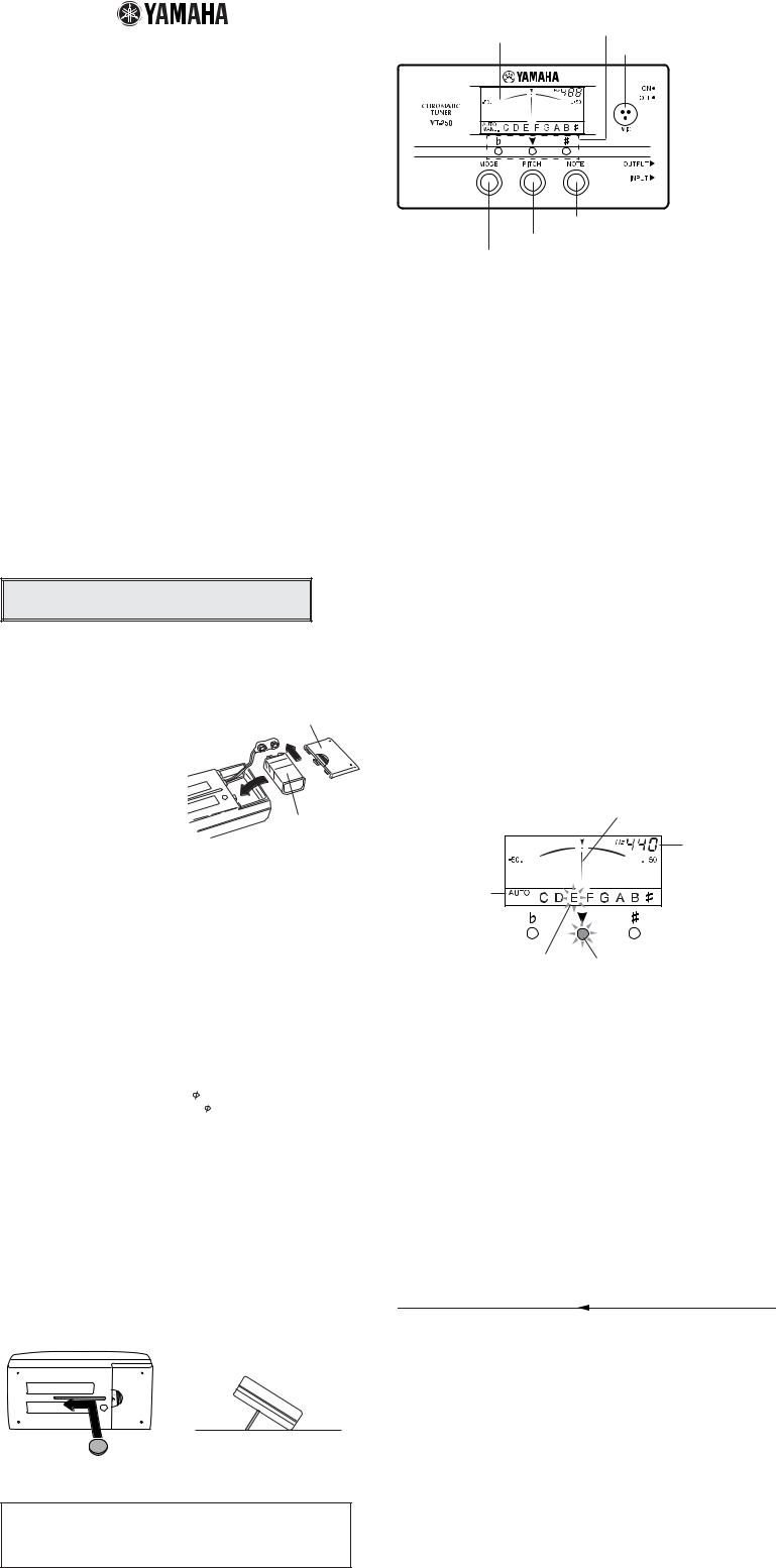
■ COMPONENTS
w Tuning guide
q LCD indicator |
y Built-in microphone |
 u POWER switch
 i OUTPUT jack
 o INPUT jack
t NOTE switch
r PITCH switch
eMODE switch
■TUNING PROCEDURES
Two tuning modes are available for tuning. The Auto (AUTO) mode automatically selects the closest note name to the pitch received by the tuner and indicates whether the pitch is high or low. The Manual (MANL.) mode allows the user to manually select the note to be tuned. Press the MODE e switch to select the desired tuning mode. The selected mode, AUTO or MANL., is displayed on the lower left hand corner of the LCD display q.
*Pressing the NOTE t switch while in the Auto mode also switches the tuner to the Manual mode.
●Auto Tuning : AUTO
1.To tune electric or electronic instruments, use a cable to connect the instrument directly to the tuner’s INPUT o jack. (Connecting the OUTPUT i jack to an amp allows the amp to receive the instrument’s signal whether the tuner’s power is on or off. However, it might result in added noise to the line so you should switch the tuner’s power off during performance.)
*The built-in microphone y will not operate when a cable is connected to the tuner’s INPUT o jack.
To tune acoustic instruments, use the tuner’s built-in microphone and play the note as close to the tuner as possible during step 4.
2.Turn the POWER u switch ON.
The standard pitch (factory preset A4=440Hz) will flash on the LCD indicator q for about 2 seconds. After that, the tuner will automatically enter the Auto tuning mode (AUTO will appear on the display q).
3.Use the PITCH switch r to change the standard pitch (refer to the “Setting the Standard Pitch” section below).
4.Play a note on the instrument (only play 1 note at a time). Use the note name indicated on the display q, the needle and tuning guide w as a reference while tuning the instrument.
4-1. First, approximately tune the instrument so that the indicator for the appropriate note name flashes.
4-2. Next, tune until the needle rests in the middle and the green LED of the tuning guide w lights.
Example) Using the AUTO mode to tune an “E”.
Tune until needle comes to rest in the center.
Standard Pitch is displayed.
Select the AUTO mode.
The note name of the string
to be tuned flashes. When this LED lights, the string is tuned.
●Manual Tuning : MANL.
1.Carry out the same settings as described in steps 1-3 in the AUTO tuning section.
2.Continue to press the NOTE t switch until the desired note name flashes. The tuner is now in the manual mode and “MANL.” appears on the display q.
3.As in step 4 of the AUTO tuning section, pluck the string to be tuned. Proceed to tune the string.
4.Repeat steps 2 and 3 to tune the other strings.
■SETTING THE STANDARD PITCH
1.Turn the POWER switch u ON. The pitch is set to 440 Hz (flashing display).
2.Continuously press the PITCH switch r until the desired standard pitch (435
– 446Hz) is selected.
 435→436→437→438→439→440→441→442→443→444→445→446
3.When the PITCH switch r has not been pressed for about 2 seconds, the tuner will automatically return to the tuning mode.
*When the POWER switch u is turned OFF, the standard pitch setting will be reset to A=440Hz.
THIS DIGITAL APPARATUS DOES NOT EXCEED THE “CLASS B” LIMITS FOR RADIO NOISE EMISSIONS FROM DIGITAL APPARATUS SET OUT IN THE RADIO INTERFERENCE REGULATION OF THE CANADIAN DEPARTMENT OF COMMUNICATIONS.
|
|
|
|
|
|
|
|
|
|
|
|
|
|
|
|
|
|
|
|
|
|
|
|
|
|
|
|
|
|
|
|
|
|
|
|
|
|
|
|
|
|
|
|
|
|
||
|
|
|
|
|
|
|
|
|
|
|
|
|
|
|
|
|
|
|
|
|
|
|
|
|
|
|
|
|
|
|
|
|
|
|
|
|
|
|
|
|
|
|
|||||
|
YT-250 |
|
|
|
|
|
|
|
|
|
|||||||||||||||||||||||||||||||||||||
|
|
|
|
|
|
|
|
|
|
|
|
|
|
||||||||||||||||||||||||||||||||||
|
|
|
|
|
|
|
|
|
|
|
|
|
|
|
|
|
|
|
|
|
|
|
|
|
|
|
|
|
|
|
|
|
|
|
|
|
|
|
|
|
|
|
|
|
|
||
|
1 |
|
|
|
|
|
|
|
|
|
|
|
|
|
|||||||||||||||||||||||||||||||||
|
|
|
|
|
|
|
|
|
|
||||||||||||||||||||||||||||||||||||||
|
|
|
|
|
|
|
|
|
|
|
|
||||||||||||||||||||||||||||||||||||
|
|
|
|
|
|
|
|
|
|
|
|
||||||||||||||||||||||||||||||||||||
|
|
|
|
|
|
|
|
|
|
|
|
|
|
|
|
|
|
|
|
|
|
|
|
|
|
|
|
|
|
|
|
|
|
|
|
|
|
|
|
|
|
|
|
||||
|
|
|
|
|
|
|
|
|
|
|
|
|
|
|
|
|
|
|
|
|
|
|
|
|
|
|
|
|
|
|
|
|
|
|
|
||||||||||||
|
|
|
|
|
|
|
|
|
|
|
|
|
|
|
|
|
|
|
|
|
|
|
|
|
|
|
|
|
|
|
|
|
|
|
|
|
|
||||||||||
|
|
|
|
|
|
|
|
|
|
|
|
|
|
|
|
|
|
|
|
|
|
|
|
|
|
|
|
|
|
|
|
|
|
|
|
|
|
|
|
|
|
|
|
|
|
||
|
|
|
|
|
|
|
|
|
|
|
|
|
|
|
|
|
|
|
|
|
|
|
|
|
|
|
|
|
|
|
|
|
|
|
|
|
|
|
|
|
|
|
|
|
|
|
|
|
|
|
|
|
|
||||||||||||||||||||||||||||||||||||||||||
|
|
|
|
|
|
|
|
|
|||||||||||||||||||||||||||||||||||||||
|
|
|
|
|
|
|
|
|
|
|
|
||||||||||||||||||||||||||||||||||||
|
|
|
|
|
|
|
|
|
|
|
|
|
|
|
|
|
|
|
|
|
|
|
|
|
|
|
|
|
|
|
|
|
|
|
|
|
|
|
|
|
|
|
|
|
|||
|
|
|
|
|
|
|
|
|
|
|
|
|
|
|
|
|
|
|
|
|
|
|
|
|
|
|
|
|
|
|
|
||||||||||||||||
|
|
|
|
|
|
|
|
|
|
|
|
|
|
|
|
|
|
|
|
|
|
|
|
|
|
|
|
|
|||||||||||||||||||
|
|
|
|
|
|
|
|
|
|
|
|
|
|
|
|
|
|
||||||||||||||||||||||||||||||
|
|
|
|
|
|
|
|
|
|
|
|
|
|
|
|
|
|
||||||||||||||||||||||||||||||
|
|
|
|
|
|
|
|
|
|
|
|
|
|
|
|||||||||||||||||||||||||||||||||
|
|
|
|
|
|
|
|
|
|
|
|
|
|
|
|
|
|
|
|
|
|
|
|
|
|
|
|
|
|
|
|
|
|
|
|
|
|
|
|
|
|
|
|
|
|
|
|
|
|
|
|
|
|
|
|
|
|
|
|
|
|
|
|
|
|
|
|
|
|
|
|
|
|
|
|
|
|
|
|
|
|
|
|
|
|
|
|
|
|
|
|
|
|
||
|
|
|
|
|
||
|
|
|
|
|
|
|
|
|
|
|
|||
|
430-8650 10 1 |
|||||
|
|
|
|
|
||
|
|
TEL 053-460-2433 |
||||
ACCORDEUR CHROMATIQUE
YT-250
MODE D’EMPLOI
Nous vous remercions d’avoir porté votre choix sur l’accordeur chromatique YAMAHA YT-250.
Nous vous prions de lire attentivement ce mode d’emploi et de le conserver en lieu sûr pour vous y reporter ultérieurement.
■PRECAUTIONS
Afin de ne pas endommager l’accordeur, évitez de l’utiliser dans des endroits répondant aux conditions suivantes :
•plein soleil
•humidité ou températures excessives.
•sable ou poussière
Pour alimenter l’accordeur, utilisez exclusivement une pile sèche 6F22 ou
006P de 9 Volts.
Pour garantir une longévité maximale des piles, mettez toujours l’accordeur hors tension lorsque vous ne l’utilisez pas.
Les piles épuisées qui restent dans l’accordeur pendant une longue période, peuvent fuir et provoquer des anomalies de fonctionnement. Lorsque les piles présentent des signes de décharge, remplacez-les dans le délai le plus bref.
L’accordeur ne doit pas subir de chocs ni de vibrations importants. Ne le manipulez jamais avec une force excessive.
N’utilisez jamais de solvants tels que de la benzine ou du diluant pour nettoyer l’accordeur. Essuyez-le avec un chiffon doux et sec.
Après avoir lu ce mode d’emploi, conservez-le en lieu sûr pour vous y reporter ultérieurement.
Ne jetez jamais les piles au feu et conservez-les toujours hors de portée des enfants.
■ REMPLACEMENT DE LA PILE
Lorsque la puissance de la pile devient insuffisante, l’afficheur à cristaux liquides s’assombrit.
Le fait de continuer à utiliser l’accordeur dans ces conditions risque de ne pas permettre de fournir une indication précise. Remplacer la pile par une pile sèche neuve (6F22 ou 006P 9 V) dans les meilleurs délais.
Le logement de la pile est situé au dos de l’accordeur. Retirer la pile usée et la remplacer par une pile neuve du même type. Faire très attention de placer la pile en respectant les polarités.
Couvercle du logement des piles
Dos de l’accordeur
Pile 6F22 ou 006P de 9 Volts
*Toujours mettre l’interrupteur POWER u sur la position “OFF” avant de remplacer la pile.
■FICHE TECHNIQUE
Indicateurs et témoins |
: Afficheur à cristaux liquides, guide d’accord |
|
|
(à 3 diodes électroluminescentes) |
|
Notes d’accord |
: C, D, E, F, G, A, B, # |
|
Plage de réglage de note |
: A0 (27Hz) - C8 (4186Hz) |
|
Précision |
: ± 1 centième |
|
Précision de hauteur |
: ± 3 centièmes |
|
Plage de réglage de hauteur standard |
|
|
|
: A4=435 - 446Hz (par incréments d’1 Hz) |
|
Entrée |
: INPUT (6 |
monaurale), microphone |
Sortie |
: OUTPUT (6 |
monaurale) |
Source d’alimentation |
: Pile sèche de 9V (006P ou 6F22) |
|
Autonomie des piles |
: 50 heures environ. (Mode AUTO) |
|
Dimensions (L x H x P) |
: 118 x 63 x 24,5 mm |
|
Poids (piles incluses) |
: 130 g |
|
Accessoires |
: Pile sèche de 9V (6F22) x 1 |
|
* Les spécifications et l’aspect externe peuvent être modifiés sans aucun avis.
■ FENTE D’INCLINAISON
L’accordeur peut être maintenu incliné en utilisant la fente du panneau arrière.
Introduire une pièce de monnaie, ou autre objet plat similaire, dans la fente et incliner l’accordeur de la manière illustrée.
■ ORGANES
q Afficheur à cristaux |
w Guide d’accord |
liquides |
y Microphone incorporé |
 u Interrupteur d’alimentation POWER
 i Mini-prise de sortie OUTPUT
 o Mini-prise
d’entrée INPUT
t Commutateur de note NOTE r Commutateur de hauteur PITCH
e Commutateur de mode MODE
■ MÉTHODES D’ACCORD
●Accord automatique : AUTO
1.Pour accorder des instruments électriques ou électroniques, utilisez un câble pour raccorder directement l’instrument à la prise INPUT o de l’accordeur. (En raccordant la prise de sortie OUTPUT i à un amplificateur, ceci permet à l’amplificateur de recevoir les signaux de l’instrument, que l’accordeur soit sous tension ou non. Cependant, il faut savoir que cela peut rajouter du bruit à la ligne de sorte qu’il est préférable de couper l’alimentation de l’accordeur pendant une interprétation.)
*Le microphone incorporé y ne fonctionnera pas si un câble est raccordé à la
prise INPUT o de l’accordeur.
Pour accorder des instruments acoustiques, utilisez le microphone incorporé de l’accordeur et jouez la note le plus près possible de l’accordeur au cours de l’étape 4.
2.Mettez l’accordeur sous tension avec l’interrupteur d’alimentation POWER u.
La hauteur standard du son (dont le préréglage a été fait sur A = 440 Hz en usine) apparaîtra en clignotant dans l’afficheur à cristaux liquides q pendant 2 secondes environ. Ensuite, l’accordeur se commutera automatiquement en mode d’accord automatique (AUTO apparaîtra dans l’afficheur à cristaux liquides q).
3.Utilisez le commutateur PITCH r pour changer la hauteur standard (reportez-vous à la description intitulée “Réglage de la hauteur standard” ci-après.)
4.Jouez une note sur l’instrument (ne jouez qu’une note à la fois.) Utilisez en même temps le nom de la note qui est indiqué dans l’afficheur q, la position de l’aiguille et le guide d’accord w comme moyen de référence
tout en accordant l’instrument.
4-1. Accordez tout d’abord l’instrument de façon globale et faites en sorte que l’indicateur du nom de note appropriée clignote.
4-2. Ensuite, accordez l’instrument jusqu’à ce que l’aiguille se stabilise en position intermédiaire et que la diode électroluminescente verte du guide d’accord w s’allume.
Exemple) Comment accorder la note “E” en mode AUTO.
Accorder jusqu’à ce que l’aiguille se stabilise en position centrale.
La hauteur |
standard est |
affichée. |
Choisir le mode |
AUTO. |
Le nom de la note de la corde |
La corde est accordée dès que la |
à accorder clignote. |
diode électroluminescente s’allume. |
●Accord manuel : MANL.
1.Effectuez les mêmes réglages que ceux qui sont décrits aux étapes 1 à 3 ci-dessus du passage consacré à l’accord réalisé en mode AUTO.
2.Maintenir le commutateur NOTE t enfoncé jusqu’à ce que le nom de la note que vous voulez obtenir clignote. L’accordeur se trouve maintenant en mode d’accord manuel et l’indication “MANL.” apparaît dans l’afficheur à cristaux liquides q.
3.Comme au cours de l’étape 4 du passage consacré au procédé d’accord en mode AUTO, pincez la corde qui doit être accordée. Faites en sorte que la corde soit accordée.
4.Refaites les étapes 2 et 3 pour accorder les autres cordes.
■RÉGLAGE DE LA HAUTEUR STANDARD
1.Mettre l’accordeur sous tension avec l’interrupteur d’alimentation POWER u. La hauteur est calée sur 440 Hz (l’afficheur clignote).
2.Maintenir le commutateur PITCH r enfoncé jusqu’à ce que la hauteur standard désirée soit otenue (435 – 446 Hz).
 435→436→437→438→439→440→441→442→443→444→445→446
3.Si le commutateur PITCH r est laissé ainsi sans être enfoncé pendant 2 secondes environ, l’accordeur reviendra automatiquement en mode d’accord.
*Lorsque l’alimentation de l’accordeur est coupée avec l’interrupteur d’alimentation POWER u, la hauteur standard est ramenée sur A = 440 Hz.
LE PRESENT APPAREIL NUMERIQUE N'EMET PAS DE BRUITS RADIOELECTRIQUES DEPASSANT LES LIMITES APPLICABLES AUX APPAREILS NUMERIQUES DE LA "CLASSE B" PRESCRITES DANS LE REGLEMENT SUR LE BROUILLAGE RADIOELECTRIQUE EDICTE PAR LE MINISTERE DES COMMUNICATIONS DU CANADA.
 Loading...