


YAMAHA YV-3910, YV-3710, YV-3700, YV-2700, YV-2700G User Manual
...CONCERT
VIBES
YV-3910/3710/3700/2700/2700G/1600A/520
Owner’s Manual
Make sure to read the PRECAUTIONS on page 1.
SPECIAL MESSAGE SECTION
This product utilizes an external power supply (adapter). DO NOT connect this product to any power supply or adapter other than one described in the manual, on the name plate, or specifically recommended by Yamaha.
WARNING: Do not place this product in a position where anyone could walk on, trip over, or roll anything over power or connecting cords of any kind. The use of an extension cord is not recommended! If you must use an extension cord, the minimum wire size for a 25" cord (or less) is 18 AWG. NOTE: The smaller the AWG number, the larger the current handling capacity. For longer extension cords, consult a local electrician.
This Product should be used only with the components supplied or; a cart, rack, or stand that is recommended by Yamaha. If a cart, etc., is used, please observe all safety markings and instructions that accompany the accessory product.
SPECIFICATIONS SUBJECT TO CHANGE: The information contained in this manual is believed to be correct at the time of printing. However, Yamaha reserves the right to change or modify any of the specifications without notice or obligation to update existing units.
NOTICE: Service charges incurred due to lack of knowledge relating to how a function or effect works (when the unit is operating as designed) are not covered by the manufacturer’s warranty; and are therefore the owners responsibility. Please study this manual carefully and consult your dealer before requesting service.
ENVIRONMENTAL ISSUES: Yamaha strives to produce products that are both user safe and environmentally friendly. We sincerely believe that our products and the production methods used to produce them, meet these goals. In keeping with both the letter and the spirit of the law, we want you to be aware of the following:
Disposal Notice: Should this Product become damaged beyond repair, or for some reason its useful life is considered to be at an end, please observe all local, state, and federal regulations that relate to the disposal of products that contain lead, batteries, plastics, etc. If your dealer is unable to assist you, Please contact Yamaha directly.
NAME PLATE LOCATION: The name Plate is located on the player side of the product. The model number, serial number, power requirements, etc., are located on this plate. You should record the model number, serial number, and the date of purchase in the spaces provided below and retain this manual as a permanent record of your purchase.
NAME
PLATE
Model
Serial No.
Purchase Date
PLEASE KEEP THIS MANUAL
PRECAUTIONS
Please read the following instructions carefully before using your vibes.
● Installation Location
Use or storage in the following locations may cause damage, even when packaged.
•In direct sunlight, such as near a window, or in a closed vehicle in daytime.
•Near heating devices or in other locations subject to excessive heat.
•In excessively cold environment.
•In places with excessive humidity or dust.
•Locations subject to vibrations.
The driver and the controller, in particular, must be protected from high humidity to avoid corrosion and short circuit.
● Do Not Use Outdoors
Avoid using the instrument outdoors. Avoid exposure to rain or moisture.
● Power Supply
Make sure to use the supplied AC adapter. Use of different adapters may cause damage not covered by the warranty.
● Handling
● When Not in Use
•Make sure to turn off the power switch and disconnect the AC adapter from the outlet.
•Always engage the caster brakes.
● Maintenance
The tone bars should be polished from time to time using a soft and dry cloth or silicone cloth. Stains that cannot be removed with a dry cloth may be wiped off using a small amount of ethyl alcohol. Never use thinner or benzene or a wet cloth for cleaning purposes.
● Keep This Manual for Future Reference
After reading, make sure to keep the manual in a safe place.
Assembly Cautions
•Never place an object on or lean against the instrument, as this may cause damage to the tone bars and frame parts or topple the instrument, which is extremely dangerous.
•Do not use hard orchestra bell mallets or other hard objects on your vibes. The resulting dents or scratches in the tone bars could impair the sound.
•Rough handling of the controller and/or the driver may cause damage to the internal circuitry.
•Never try to disassemble the controller or driver, as this may result in severe damage.
•When assembling/disassembling the instrument, make sure to follow the procedure outlined in this manual. Assembly in the wrong order may impair the performance and functionality of the instrument or cause noise.
•Make sure to adjust the wire clip positions after assembly. (YV-3910/3710/3700: P. 17)
•Height adjustment of the striking surface (YV3910/3710/3700: P. 18, YV-2700/2700G/ 1600A/520: P 25) should be performed by AT LEAST 2 PERSONS.
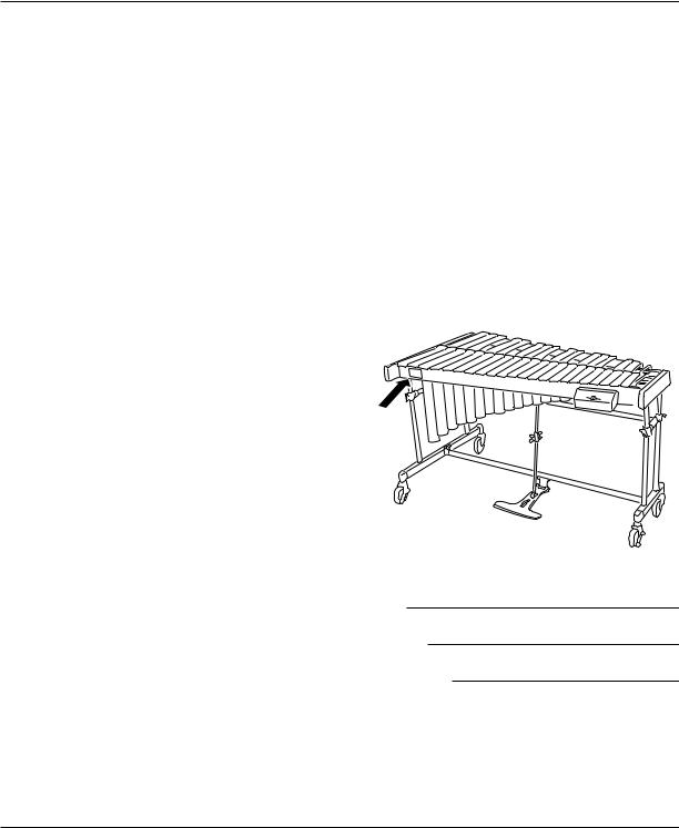
● Moving and Transporting the Instrument
•Move the instrument carefully to avoid shocks. Before moving the instrument, make sure that the AC adapter is disconnected and the caster brakes are released. Also make sure to lift the instrument slightly when moving over rough surfaces.
•When the instrument must be transported to a different location make sure to fully disassemble it, taking care to pack each component properly. Disassembly steps are in the opposite order of assembly.
•After final adjustment of the legs the fixing screws must be tightened securely to prevent loosening. Looseness may cause the instrument to shift during performance and can also cause noise and other problems. Retighten the screws from time to time.
1

NOMENCLATURE : YV-3910/3710/3700/2700/2700G/1600A/520
Accidental Tone Bars
Natural Tone Bars
Controller
Fan Belt
Frame End
(Large) Frame End
(Small)
Rail No. 1 |
|
Slide Leg |
Resonators |
|
|
(Natural Tone Side) |
|
Slant Shaft |
|
|
Driver |
Leg (Large) |
|
|
|
Resonators |
Leg (Small) |
Pedal Stay |
(Accidental |
|
|
Tone Side) |
|
Pedal |
|
Caster |
AC Adapter |
* The illustration shows model YV-3710 |
|
■Vibes Drive Unit
●Controller (Player Side)
q POWER Switch
Turns the power on and off.
w MOTOR SPEED Slider
Controls the fan rotation speed. e LED Indicator
Lights when the power is turned on and flashes while the fan is rotating.
r START/STOP Button
Starts and stops fan rotation.
t DC 12V IN Jack
y MOTOR OUT Terminal
u MOTOR IN Terminal
i 8P DIN Cable
o AC Adapter
● Controller (Right Side)
● Driver (Player Side)
2

CONFIRMATION OF PACKING CONTENTS : YV-3700
The shipping carton of your YV-3700 should contain the parts shown below. Before assembling the instrument, confirm that all parts are included as listed.
* In the event that a part is missing, please contact the shop where the instrument was purchased.
q Natural Tone Bars |
i Rail (1) : Player Side |
|
|
Name Plate |
|
|
o Rail (2) : Player Side |
Posts (Larger |
|
number than parts |
|
|
Rail Clamp !0and !1) |
|
w Accidental Tone Bars |
|
|
|
!0Rail (3) : Audience Side |
Rail Clamp Posts |
|
|
|
e Resonators (Natural Tone Side) |
!1Rail (4) : Audience Side |
|
YAMAHA Logo |
Posts |
|
|
!2Leg (Large) |
!3Leg (Small) |
r Resonators (Accidental Tone Side) |
|
|
!4AC Adapter |
!5Synchro Belt |
t Sustain Damper |
(Fan Belt): 2 pcs. |
|
y Reinforcement Stay |
|
Vibes Drive Unit: YVM-300 |
|
||
|
|
||||
!6Driver |
!7Controller |
||||
|
|||||
u Pedal Stay |
|
|
|
|
|
|
|
|
!88P DIN Cable |
||
|
|
|
|
|
|
3

CONFIRMATION OF PACKING CONTENTS : YV-3910/3710
The shipping carton of your YV-3910/3710 should contain the parts shown below. Before assembling the instrument, confirm that all parts are included as listed.
* In the event that a part is missing, please contact the shop where the instrument was purchased.
q Natural Tone Bars u Rail (1) : Player Side
w Accidental Tone Bars
e Resonators (Natural Tone Side)
r Resonators (Accidental Tone Side)
t Sustain Damper
y Pedal Stay
Name Plate |
|
|
i Rail (2) |
: Player Side |
Posts (Larger |
number than parts |
||
|
Rail Clamp |
o and !0) |
o Rail (3) |
: Audience Side |
|
|
Rail Clamp Posts |
|
!0Rail (4) : Audience Side
Posts
YAMAHA Logo
!1Leg (Large) |
!2Leg (Small) |
!3AC Adapter |
!4Synchro Belt |
|
(Fan Belt): 2 pcs. |
Vibes Drive Unit: YVM-300
!5Driver |
!6Controller |
!78P DIN Cable
4

CONFIRMATION OF PACKING CONTENTS : YV-3910/3710
■ Dividable Parts and Collapsible Parts (YV-3910/3710 only)
The YV-3910’s/YV-3710’s large parts are designed to either divide or collapse. When the instrument is broken down, its compact size makes it easy to transport and storage requires a minimum amount of space.
● Rails
The rails fold in from the center.
● Pedal Stay
The pedal stay divides into left and right sections and the pedal itself. Loosen the 2 wing nuts and remove the stays from the pedal attachment.
Loosen
● Sustain Damper
The sustain damper divides into 2 sections.
Loosen the bolt and separate left and right sections.
Loosen
● Resonators
Both resonators divide into two sections. |
Pin |
Notch |
Loosen both bolts and separate left and right sections. |
|
|
*When assembling the resonators, make sure that the pin and notch are properly aligned.
Loosen
5

ASSEMBLY : YV-3910/3710/3700
For safety, assembly should be performed by at least 2 persons in a location with sufficient space. We recommend to you to assemble the instrument on a soft rug or carpet.
zConnect the large and the small leg using the reinforcement stay and pedal stay.
*Before proceeding, make sure that the slide leg fixing bolts of the large and small leg are securely fastened.
Leg (Large) |
Leg (Small) |
The tip of each slide leg fixing bolt must be tightly seated in one of the slide leg notches.
Slide Leg
Slide Leg
Fixing Bolt
|
Slide Leg |
Slide Leg |
Fixing Bolt |
Slide Leg |
|
Fixing Bolt |
Fixing Bolt |
1-1 ● YV-3910/3710 : Place the large leg, small leg, pedal stay (and reinforcement stay : YV-3700) so that after assembly each part will be positioned as illustrated.
Low Sound |
Leg (Large) |
|
Side |
|
|
|
|
|
|
Slant Shaft |
Audience Side |
|
Leg (Small) |
|
|
|
|
|
|
High Sound |
|
|
Side |
Pedal Stay
Pedal
Player Side
Align flat surfaces. Flat surface should face player side.
6

ASSEMBLY: YV-3910/3710/3700
1-2 ● YV-3910/3710 : Insert the pedal stay with its notch facing up into the lower joint of the large leg as far as it will go (aligning the notch with the fixing bolt) and tighten the fixing bolt securely.
*The hole next to the notch serves as a reference for the correct insertion position.
1-3 |
● YV-3910/3710 : Connect the other ends of the pedal stay with the small leg in the same way. |
|||
|
Leg |
|
Fixing |
|
|
Tighten |
Bolt |
|
|
|
(Large) |
Reference Hole |
||
|
|
|||
|
|
|
Pedal Stay |
|
|
|
|
Leg (Large) |
Pedal Stay |
|
|
|
Notch |
Notch |
|
|
|
|
|
1-4 |
● YV-3910/3710 : Loosen the slant shaft bolt, extend the shaft and insert the shaft end into the |
|||
|
|
leg joint. |
|
|
|
|
With the notch aligned with the fixing bolt (the same as in the pedal stay |
||
|
|
assembly) tighten the fixing bolt securely. |
|
|
1-5 |
● YV-3910/3710 : Connect the other side slant shaft with the small leg in the same way. |
|||
Leg Joint
Notch
Slant Shaft Bolt
7
 Loading...