


 Loading...
YFM4FAT
YFM400FAT
5TE2-AE2
SUPPLEMENTARY SERVICE MANUAL

FOREWORD
This Supplementary Service Manual has been prepared to introduce new service and data for the YFM4FAT/YFM400FAT. For complete service information procedures it is necessary to use this Supplementary Service Manual together with the following manual.
YFM4FAR/YFM400FAR SERVICE MANUAL: 5TE2-AE1
YFM4FAT/YFM400FAT
SUPPLEMENTARY
SERVICE MANUAL ©2004 by Yamaha Motor Co., Ltd.
First edition, June 2004 All rights reserved.
Any reproduction or unauthorized use without the written permission of Yamaha Motor Co., Ltd.
is expressly prohibited.

EB001000
NOTICE
This manual was produced by the Yamaha Motor Company primarily for use by Yamaha dealers and their qualified mechanics. It is not possible to include all the knowledge of a mechanic in one manual, so it is assumed that anyone who uses this book to perform maintenance and repairs on Yamaha machine has a basic understanding of the mechanical ideas and the procedures of machine repair. Repairs attempted by anyone without this knowledge are likely to render the machine unsafe and unfit for use.
Yamaha Motor Company, Ltd. is continually striving to improve all its models. Modifications and significant changes in specifications or procedures will be forwarded to all authorized Yamaha dealers and will appear in future editions of this manual where applicable.
NOTE:
Designs and specifications are subject to change without notice.
IMPORTANT INFORMATION
Particularly important information is distinguished in this manual by the following notations.
|
|
The Safety Alert Symbol means ATTENTION! BECOME ALERT! YOUR |
|
|
SAFETY IS INVOLVED! |
|
|
|
WARNING |
Failure to follow WARNING instructions could result in severe injury or death |
|
|
|
to the machine operator, a bystander or a person inspecting or repairing the |
|
|
machine. |
|
|
|
CAUTION: |
|
A CAUTION indicates special precautions that must be taken to avoid |
|
|
damage to the machine. |
NOTE: |
A NOTE provides key information to make procedures easier or clearer. |
|

EB002000
HOW TO USE THIS MANUAL
MANUAL ORGANIZATION
This manual consists of chapters for the main categories of subjects. (See “Illustrated symbols”)
1st title 1: This is the title of the chapter with its symbol in the upper right corner of each page.
2nd title 2: This title indicates the section of the chapter and only appears on the first page of each section. It is located in the upper left corner of the page.
3rd title 3: This title indicates a sub-section that is followed by step-by-step procedures accompanied by corresponding illustrations.
EXPLODED DIAGRAMS
To help identify parts and clarify procedure steps, there are exploded diagrams at the start of each removal and disassembly section.
1.An easy-to-see exploded diagram 4 is provided for removal and disassembly jobs.
2.Numbers 5 are given in the order of the jobs in the exploded diagram. A number that is enclosed by a circle indicates a disassembly step.
3.An explanation of jobs and notes is presented in an easy-to-read way by the use of symbol marks
6.The meanings of the symbol marks are given on the next page.
4.A job instruction chart 7 accompanies the exploded diagram, providing the order of jobs, names of parts, notes in jobs, etc.
5.For jobs requiring more information, the step-by-step format supplements 8 are given in addition to the exploded diagram and the job instruction chart.

1 |
|
|
2 |
GEN |
|
|
SPEC |
INFO |
|
|
|
|
|
|
|
3 |
|
|
4 |
CHK |
|
|
ENG |
ADJ |
|
|
|
|
|
|
|
5 |
|
|
6 |
COOL |
|
|
CARB |
7 |
|
|
8 |
DRIV |
|
|
CHAS |
9 |
|
|
0 |
ELEC – |
+ |
|
TRBL |
|
|
|
SHTG |
A |
|
|
B |
C |
|
|
D |
E |
|
|
F |
T |
|
|
|
. |
|
|
|
R |
|
|
|
. |
|
|
|
G |
|
|
H |
I |
J |
|
K |
E |
|
G |
M |
L |
M |
|
N |
B |
|
LS |
M |
O |
|
|
P |
LT |
|
|
New |
|
|
|
EB003000
ILLUSTRATED SYMBOLS
Illustrated symbols 1 to 0 are printed on the top right of each page and indicate the subject of each chapter.
1 General information
2Specifications
3Periodic checks and adjustments
4Engine
5Cooling system
6Carburetion
7Drive train
8Chassis
9Electrical
0 Troubleshooting
Illustrated symbols A to H are used to identify the specifications appearing in the text.
A Can be serviced with engine mounted B Filling fluid
CLubricant
DSpecial tool
ETorque
FWear limit, clearance
GEngine speed
HΩ, V, A
Illustrated symbols I to N in the exploded diagrams indicate the types of lubricants and lubrication points.
I Apply engine oil
J Apply gear oil
K Apply molybdenum disulfide oil
L Apply wheel bearing grease
MApply lithium-soap-based grease
NApply molybdenum disulfide grease
Illustrated symbols O to P in the exploded diagrams indicate where to apply a locking agent O and when to install a new part P.
OApply the locking agent (LOCTITE®)
PReplace

CONTENTS |
|
SPECIFICATIONS ............................................................................................ |
1 |
GENERAL SPECIFICATIONS .................................................................. |
1 |
MAINTENANCE SPECIFICATIONS ......................................................... |
3 |
ENGINE ................................................................................................ |
3 |
CHASSIS .............................................................................................. |
4 |
ELECTRICAL ........................................................................................ |
6 |
CABLE ROUTING ..................................................................................... |
7 |
PERIODIC CHECKS AND ADJUSTMENTS .................................................. |
18 |
INTRODUCTION ..................................................................................... |
18 |
PERIODIC MAINTENANCE/LUBRICATION ........................................... |
18 |
SEAT, CARRIERS, FENDERS AND FUEL TANK .................................. |
20 |
FRONT CARRIER, FRONT BUMPER AND FRONT FENDER .......... |
20 |
CHASSIS ................................................................................................. |
22 |
ADJUSTING THE REAR BRAKE ....................................................... |
22 |
CHECKING THE BRAKE FLUID LEVEL ............................................ |
24 |
CHECKING THE REAR BRAKE PADS .............................................. |
25 |
CHECKING THE BRAKE HOSES ...................................................... |
25 |
BLEEDING THE HYDRAULIC BRAKE SYSTEM ............................... |
26 |
ADJUSTING THE SELECT LEVER CONTROL CABLE |
|
AND SHIFT ROD ................................................................................ |
27 |
CHECKING THE FINAL GEAR OIL LEVEL ........................................ |
29 |
CHECKING THE CONSTANT VELOCITY JOINT DUST BOOTS ...... |
29 |
ADJUSTING THE REAR SHOCK ABSORBERS ............................... |
30 |
ENGINE .......................................................................................................... |
31 |
CRANKCASE .......................................................................................... |
31 |
STARTER MOTOR, TIMING CHAIN AND OIL FILTER ..................... |
31 |
CRANKCASE ...................................................................................... |
34 |
INSTALLING THE SHIFT LEVER ....................................................... |
35 |
TRANSMISSION ..................................................................................... |
36 |
CHECKING THE STOPPER LEVER AND STOPPER WHEEL ......... |
38 |
MIDDLE GEAR ........................................................................................ |
39 |
MIDDLE DRIVEN SHAFT ................................................................... |
39 |
DRIVE TRAIN ................................................................................................. |
41 |
TROUBLESHOOTING ............................................................................ |
41 |
FRONT CONSTANT VELOCITY JOINTS |
|
AND DIFFERENTIAL GEAR .................................................................. |
44 |
MEASURING AND ADJUSTING THE DIFFERENTIAL |
|
GEAR LASH ........................................................................................ |
44 |

REAR CONSTANT VELOCITY JOINTS, FINAL DRIVE GEAR |
|
AND DRIVE SHAFT ............................................................................... |
46 |
ASSEMBLING THE REAR CONSTANT VELOCITY JOINTS ............ |
51 |
DISASSEMBLING THE FINAL DRIVE GEAR .................................... |
52 |
CHECKING THE DRIVE SHAFT/UNIVERSAL JOINT YOKE ............ |
52 |
CHECKING THE FINAL DRIVE GEAR ............................................... |
53 |
REPLACING THE FINAL DRIVE ROLLER BEARING ....................... |
53 |
REPLACING THE FINAL DRIVE PINION GEAR AND BEARING ...... |
54 |
POSITIONING THE FINAL DRIVE PINION GEAR ............................. |
56 |
MEASUREMENT AND ADJUSTING THE FINAL GEAR LASH ......... |
57 |
ASSEMBLING THE FINAL DRIVE GEAR .......................................... |
60 |
CHASSIS ........................................................................................................ |
62 |
FRONT AND REAR WHEELS ................................................................ |
62 |
REAR WHEELS .................................................................................. |
62 |
INSTALLING THE REAR BRAKE DISC ............................................. |
64 |
INSTALLING THE REAR WHEEL HUBS ........................................... |
64 |
REAR BRAKE ......................................................................................... |
65 |
REAR BRAKE PADS .......................................................................... |
65 |
REPLACING THE REAR BRAKE PADS ............................................ |
66 |
REAR BRAKE MASTER CYLINDER .................................................. |
68 |
CHECKING THE MASTER CYLINDER .............................................. |
71 |
ASSEMBLING THE REAR BRAKE MASTER CYLINDER ................. |
71 |
INSTALLING THE REAR BRAKE MASTER CYLINDER .................... |
72 |
REAR BRAKE CALIPER ..................................................................... |
74 |
DISASSEMBLING THE REAR BRAKE CALIPER .............................. |
76 |
CHECKING THE REAR BRAKE CALIPER ........................................ |
76 |
ASSEMBLING THE REAR BRAKE CALIPER .................................... |
77 |
INSTALLING THE REAR BRAKE CALIPER ...................................... |
78 |
STEERING SYSTEM .............................................................................. |
80 |
STEERING STEM ............................................................................... |
80 |
FRONT ARMS AND FRONT SHOCK ABSORBERS ............................. |
82 |
REAR KNUCKLES AND STABILIZER .................................................... |
84 |
CHECKING THE REAR KNUCKLES .................................................. |
85 |
CHECKING THE STABILIZER ........................................................... |
85 |
REAR ARMS AND REAR SHOCK ABSORBERS .................................. |
86 |
CHECKING THE REAR ARMS ........................................................... |
87 |
INSTALLING THE REAR ARMS AND REAR SHOCK ABSORBERS .... |
87 |
ELECTRICAL ................................................................................................. |
88 |
ELECTRICAL COMPONENTS ............................................................... |
88 |
CHECKING THE SWITCHES ................................................................. |
89 |
CHECKING THE SWITCH CONTINUITY ........................................... |
89 |
SIGNAL SYSTEM ................................................................................... |
91 |
CIRCUIT DIAGRAM ............................................................................ |
91 |
CHECKING THE SIGNAL SYSTEM ................................................... |
93 |
YFM4FAT/YFM400FAT WIRING DIAGRAM

|
|
|
|
|
|
|
GENERAL SPECIFICATIONS |
|
SPEC |
|
|
|
|
|
|
|
|
|
SPECIFICATIONS |
||||
GENERAL SPECIFICATIONS |
|
|
|
|
|
|
|
|
|||
Item |
|
Standard |
|||
|
|
|
|||
Model code: |
|
1P11, 1P14 (for USA) |
|||
|
|
1P12 (for CDN) |
|||
|
|
1P13 (for Oceania) |
|||
|
|
|
|
|
|
Dimensions: |
|
|
|
|
|
Overall length |
|
1,993 mm (78.5 in) |
|||
Overall width |
|
1,093 mm (43.0 in) |
|||
Overall height |
|
1,120 mm (44.1 in) |
|||
Seat height |
|
830 mm (32.7 in) |
|||
Wheelbase |
|
1,233 mm (48.5 in) |
|||
Minimum ground clearance |
|
245 mm (9.7 in) |
|||
Minimum turning radius |
|
3,000 mm (118.1 in) |
|||
|
|
|
|
|
|
Basic weight: |
|
|
|
|
|
With oil and full fuel tank |
|
279 kg (615 lb) (for USA and CDN) |
|||
|
|
283 kg (624 lb) (for Oceania) |
|||
|
|
|
|
|
|
Oil capacity: |
|
|
|
|
|
Engine oil |
|
|
|
|
|
Periodic oil change |
|
2.30 L (2.02 Imp qt, 2.43 US qt) |
|||
With oil filter replacement |
|
2.40 L (2.11 Imp qt, 2.54 US qt) |
|||
Total amount |
|
2.60 L (2.29 Imp qt, 2.75 US qt) |
|||
Final gear case oil |
|
|
|
|
|
Periodic oil change |
|
0.16 L (0.14 Imp qt, 0.17 US qt) |
|||
Total amount |
|
0.18 L (0.16 Imp qt, 0.19 US qt) |
|||
Differential gear case oil |
|
|
|
|
|
Periodic oil change |
|
0.35 L (0.31 Imp qt, 0.37 US qt) |
|||
Total amount |
|
0.40 L (0.35 Imp qt, 0.42 US qt) |
|||
Radiator capacity (including all routes) |
1.32 L (1.16 Imp qt, 1.40 US qt) |
||||
|
|
|
|
|
|
Chassis: |
|
|
|
|
|
Frame type |
|
Steel tube frame |
|||
Caster angle |
|
2.5° |
|
|
|
Camber angle |
|
1° |
|
|
|
Kingpin angle |
|
11° |
|
|
|
Kingpin offset |
|
0 mm (0 in) |
|||
Trail |
|
8.5 mm (0.33 in) |
|||
Tread (STD) |
front |
850 mm (33.46 in) |
|||
|
rear |
839 mm (33.03 in) |
|||
Toe-in |
|
0 ~ 10 mm (0 ~ 0.39 in) |
|||
|
|
|
|
|
|
– 1 –

|
|
|
|
|
|
|
GENERAL SPECIFICATIONS |
|
SPEC |
|
|
|
|
|
|
|
|
|
|
|
|||
Item |
|
Standard |
|||
|
|
|
|
|
|
Tires: |
|
|
|
|
|
Type |
|
Tubeless |
|||
Size |
front |
AT25 × 8–12 |
|||
|
rear |
AT25 × 10–12 |
|||
Manufacturer |
front |
MAXXIS (for USA and CDN) |
|||
|
|
CHENG SHIN (for Oceania) |
|||
|
rear |
MAXXIS (for USA and CDN) |
|||
|
|
CHENG SHIN (for Oceania) |
|||
Model |
front |
M911Y (for USA and CDN) |
|||
|
|
C828 (for Oceania) |
|||
|
rear |
M912Y (for USA and CDN) |
|||
|
|
C828 (for Oceania) |
|||
|
|
|
|
|
|
Brakes: |
|
|
|
|
|
Front brake |
type |
Dual disc brake |
|||
|
operation |
Right hand operation |
|||
Rear brake |
type |
Single disc brake |
|||
|
operation |
Left hand and right foot operation |
|||
|
|
|
|
|
|
Suspension: |
|
|
|
|
|
Front suspension |
|
Double wishbone |
|||
Rear suspension |
|
Double wishbone |
|||
|
|
|
|
|
|
Bulb wattage × quantity: |
|
|
|
|
|
Headlight |
|
12 V 30 W/30 W × 2 |
|||
Tail/brake light |
|
12 V 5 W/21 W × 1 |
|||
Meter light |
|
14 V 3 W × 1 |
|||
Indicator lights |
|
|
|
|
|
Neutral |
|
12 V 1.7 W × 1 |
|||
Reverse |
|
12 V 1.7 W × 1 |
|||
Park |
|
12 V 1.7 W × 1 |
|||
Coolant temperature |
|
12 V 1.7 W × 1 |
|||
Four-wheel drive |
|
12 V 1.7 W × 1 |
|||
– 2 –
MAINTENANCE SPECIFICATIONS SPEC
MAINTENANCE SPECIFICATIONS
ENGINE
Item |
|
|
|
|
|
|
Standard |
|
|
Limit |
|
|
|
|
|
|
|
|
|
|
|
|
|
Carburetor: |
|
|
|
|
|
|
|
|
|
|
|
I. D. mark |
|
|
5TEC 00 |
|
|
|
|
---- |
|||
Main jet |
(M.J) |
|
#132.5 |
|
|
|
|
|
---- |
||
Main air jet |
(M.A.J) |
|
#50 |
|
|
|
|
|
|
|
---- |
Jet needle |
(J.N) |
|
5EP13-55-3 |
|
|
|
|
---- |
|||
Needle jet |
(N.J) |
|
P-0M |
|
|
|
|
|
|
---- |
|
Pilot air jet |
(P.A.J.1) |
|
#80 |
|
|
|
|
|
|
|
---- |
Pilot air jet |
(P.A.J.2) |
|
1.3 |
|
|
|
|
|
|
|
---- |
Pilot outlet |
(P.O) |
|
0.95 |
|
|
|
|
|
|
|
---- |
Pilot jet |
(P.J) |
|
#17.5 |
|
|
|
|
|
|
---- |
|
Bypass 1 |
(B.P.1) |
|
0.8 |
|
|
|
|
|
|
|
---- |
Bypass 2 |
(B.P.2) |
|
0.8 |
|
|
|
|
|
|
|
---- |
Bypass 3 |
(B.P.3) |
|
0.8 |
|
|
|
|
|
|
|
---- |
Pilot screw |
(P.S.) |
|
2-1/2 turns out |
|
|
|
---- |
||||
Valve seat size |
(V.S) |
|
2.0 |
|
|
|
|
|
|
|
---- |
Starter jet |
(G.S.1) |
|
#75 |
|
|
|
|
|
|
|
---- |
Starter jet |
(G.S.2) |
|
0.9 |
|
|
|
|
|
|
|
---- |
Throttle valve size |
(Th.V) |
|
#90 |
|
|
|
|
|
|
|
---- |
Float height |
(F.H) |
|
13 mm (0.51 in) |
|
|
|
---- |
||||
Fuel level |
(F.L) |
|
4.0 ~ 5.0 mm (0.16 ~ 0.20 in) |
---- |
|||||||
Engine idle speed |
|
|
1,450 ~ 1,550 r/min |
|
|
---- |
|||||
Intake vacuum |
|
|
33.3 kPa (250 mmHg, 9.84 inHg) |
---- |
|||||||
|
|
|
|
|
|
|
|
|
|
|
|
Tightening torques |
|
|
|
|
|
|
|
|
|
|
|
|
|
|
|
|
|
|
|
|
|
|
|
Part to be tightened |
Part |
Thread |
|
Q’ty |
|
Tightening torque |
|
Remarks |
|||
|
|
|
|
|
|
||||||
name |
|
size |
|
|
Nm |
m · kg |
ft · lb |
|
|||
|
|
|
|
|
|
|
|||||
|
|
|
|
|
|
|
|
|
|
|
|
Shift lever 2 assembly |
Bolt |
|
M6 |
|
1 |
|
14 |
1.4 |
10 |
|
|
Shift lever cover |
Bolt |
|
M6 |
|
4 |
|
10 |
1.0 |
7.2 |
|
|
Stopper lever |
Bolt |
|
M6 |
|
1 |
|
10 |
1.0 |
7.2 |
|
|
Stopper lever shaft |
Bolt |
|
M6 |
|
1 |
|
10 |
1.0 |
7.2 |
|
|
Park switch |
— |
M10 |
|
1 |
|
20 |
2.0 |
14 |
|
|
|
|
|
|
|
|
|
|
|
|
|
|
|
– 3 –

MAINTENANCE SPECIFICATIONS SPEC
CHASSIS
Item |
|
Standard |
Limit |
|
|
|
|
Front suspension: |
|
|
|
Shock absorber travel |
|
99 mm (3.90 in) |
---- |
Spring free length |
|
285 mm (11.22 in) |
---- |
Spring fitting length |
|
231.9 mm (9.13 in) |
---- |
Spring rate |
(K1) |
15 N/mm |
---- |
|
|
(1.53 kg/mm, 85.68 lb/in) |
|
Stroke |
(K1) |
0 ~ 99 mm (0 ~ 3.90 in) |
---- |
Optional spring |
|
No |
---- |
|
|
|
|
Rear suspension: |
|
|
|
Shock absorber travel |
|
95 mm (3.74 in) |
---- |
Spring free length |
|
277.9 mm (10.94 in) |
---- |
Spring fitting length |
|
247.9 mm (9.76 in) |
---- |
Spring rate |
(K1) |
27 N/mm |
---- |
|
|
(2.75 kg/mm, 153.99 lb/in) |
|
Stroke |
(K1) |
0 ~ 95 mm (0 ~ 3.74 in) |
---- |
Optional spring |
|
No |
---- |
|
|
|
|
Rear disc brake: |
|
|
|
Type |
|
Single |
---- |
Disc outside diameter × thickness |
|
220.0 × 3.5 mm (8.66 ~ 0.14 in) |
---- |
Pad thickness |
inner |
5.0 mm (0.20 in) |
1 mm |
|
|
|
(0.04 in) |
Pad thickness |
outer |
5.0 mm (0.20 in) |
1 mm |
|
|
|
(0.04 in) |
Master cylinder inside diameter |
|
14 mm (0.55 in) |
---- |
Caliper cylinder inside diameter |
|
32.03 mm (1.26 in) |
---- |
Brake fluid type |
|
DOT 4 |
---- |
|
|
|
|
Brake lever and brake pedal: |
|
|
|
Brake lever free play (pivot) |
front |
0 mm (0 in) |
---- |
|
rear |
0.5 ~ 2.0 mm (0.02 ~ 0.08 in) |
---- |
Brake pedal height |
|
67 ~ 77 mm (2.64 ~ 3.03 in) |
---- |
Throttle lever free play |
|
3 ~ 5 mm (0.12 ~ 0.20 in) |
---- |
|
|
|
|
– 4 –

|
|
|
|
|
|
|
|
|
|
|
|
MAINTENANCE SPECIFICATIONS |
|
SPEC |
|
|
|
|
|||||
|
|
|
|
|
|
|
|
|
|
|
|
Tightening torques |
|
|
|
|
|
|
|
|
|
|
|
|
|
|
|
|
|
|
|
|
|
|
|
|
|
|
|
|
|
|
|
|
|
|
|
Part to be tightened |
Thread |
Tightening torque |
|
Remarks |
|||||||
size |
|
|
|
|
|
||||||
Nm |
m · kg |
|
ft · lb |
|
|||||||
|
|
|
|
|
|
|
|
||||
|
|
|
|
|
|
|
|
|
|
|
|
Rear shock absorber and sub-frame |
M10 |
45 |
4.5 |
32 |
|
|
|
|
|
|
|
Rear shock absorber and rear lower arm |
M10 |
45 |
4.5 |
32 |
|
|
|
|
|
|
|
Rear upper arm and sub-frame |
M10 |
45 |
4.5 |
32 |
|
|
LS |
|
|
||
|
|
|
|||||||||
Rear lower arm and sub-frame |
M10 |
45 |
4.5 |
32 |
|
|
|
|
|
||
|
|
LS |
|
|
|||||||
|
|
|
|
||||||||
Rear upper arm and rear knuckle |
M10 |
45 |
4.5 |
32 |
|
|
|
|
|
|
|
|
|
|
|
|
|
||||||
Rear lower arm and rear knuckle |
M10 |
45 |
4.5 |
32 |
|
|
|
|
|
|
|
Stabilizer and sub-frame |
M8 |
30 |
3.0 |
22 |
|
|
|
|
|
|
|
Stabilizer joint and stabilizer |
M10 |
56 |
5.6 |
40 |
|
|
|
|
|
|
|
Stabilizer joint and rear lower arm |
M10 |
56 |
5.6 |
40 |
|
|
|
|
|
|
|
Frame and sub-frame (front lower) |
M12 |
82 |
8.2 |
59 |
|
|
|
|
|
|
|
Frame and sub-frame (rear upper) |
M10 |
48 |
4.8 |
35 |
|
|
|
|
|
|
|
Final drive gear case and sub-frame |
M10 |
45 |
4.5 |
32 |
|
|
|
|
|
|
|
Trailer hitch and sub-frame |
M10 |
40 |
4.0 |
29 |
|
|
|
|
|
|
|
Brake disc guard and steering knuckle |
M6 |
7 |
0.7 |
5.1 |
|
|
|
|
|
|
|
Front lower arm and protector |
M6 |
7 |
0.7 |
5.1 |
|
|
|
|
|
|
|
Steering stem, pitman arm and frame |
M14 |
190 |
19.0 |
140 |
|
|
|
|
|
|
|
Fuel tank and frame |
M6 |
10 |
1.0 |
7.2 |
|
|
|
|
|
|
|
Front wheel and wheel hub |
M10 |
55 |
5.5 |
40 |
|
|
|
|
|
|
|
Rear axle and wheel hub |
M20 |
260 |
26.0 |
190 |
|
Stake |
|||||
Rear knuckle and brake caliper |
M8 |
30 |
3.0 |
22 |
|
|
|
|
|
|
|
Brake disc guard and rear knuckle |
M6 |
7 |
0.7 |
5.1 |
|
|
|
|
|
|
|
Rear brake disc and wheel hub |
M8 |
30 |
3.0 |
22 |
|
|
|
LT |
|||
|
|
||||||||||
|
|
||||||||||
Front brake pipe joint and frame |
M6 |
7 |
0.7 |
5.1 |
|
|
|
|
|
|
|
Brake hose holder and steering knuckle |
M6 |
7 |
0.7 |
5.1 |
|
|
|
|
|
|
|
Brake hose holder and front upper arm |
M6 |
7 |
0.7 |
5.1 |
|
|
|
|
|
|
|
Rear brake hose union bolt |
M10 |
30 |
3.0 |
22 |
|
|
|
|
|
|
|
Rear brake pad holding bolt |
M10 |
17 |
1.7 |
12 |
|
|
|
LT |
|||
|
|
||||||||||
|
|
||||||||||
Rear brake master cylinder |
M8 |
23 |
2.3 |
17 |
|
|
|
|
|
|
|
Rear brake master cylinder bracket |
M8 |
30 |
3.0 |
22 |
|
|
|
|
|
|
|
Rear brake master cylinder cover |
M6 |
7 |
0.7 |
5.1 |
|
|
|
|
|
|
|
Rear brake pipe nut |
M10 |
19 |
1.9 |
13 |
|
|
|
|
|
|
|
Rear brake pipe joint and frame |
M6 |
7 |
0.7 |
5.1 |
|
|
|
|
|
|
|
Final drive gear case filler bolt |
M14 |
23 |
2.3 |
17 |
|
|
|
|
|
|
|
Final drive gear case drain bolt |
M14 |
23 |
2.3 |
17 |
|
|
|
|
|
|
|
Final drive gear case and bearing housing |
M10 |
40 |
4.0 |
29 |
|
|
|
|
|
|
|
Final drive gear case and bearing housing |
M8 |
23 |
2.3 |
17 |
|
|
|
|
|
|
|
Bearing retainer (final drive pinion gear) |
M75 |
115 |
11.5 |
85 |
|
Left-hand |
|||||
|
|
|
|
|
|
|
threads |
||||
Universal joint yoke (final drive pinion gear) |
M14 |
97 |
9.7 |
70 |
|
|
|
|
|
|
|
Ring gear stopper |
M8 |
16 |
1.6 |
11 |
|
|
|
|
|
|
|
Air duct assembly 1 and frame |
M6 |
7 |
0.7 |
5.1 |
|
|
|
|
|
|
|
Engine skid plate and frame |
M6 |
7 |
0.7 |
5.1 |
|
|
|
|
|
|
|
Final gear case skid plate and sub-frame |
M6 |
7 |
0.7 |
5.1 |
|
|
|
|
|
|
|
|
|
|
|
|
|
|
|
|
|
|
|
– 5 –

MAINTENANCE SPECIFICATIONS SPEC
ELECTRICAL
Item |
Standard |
Limit |
|
|
|
C.D.I.: |
|
|
Magneto model/manufacturer |
F4T464/MITSUBISHI |
---- |
Pickup coil resistance/color |
459 ~ 561 Ω at 20 °C (68 °F)/ |
---- |
|
White/Red – White/Green |
|
Rotor rotation direction sensing coil resis- |
0.086 ~ 0.105 Ω at 20 °C (68 °F)/ |
---- |
tance/color |
Red – White/Blue |
|
C.D.I. unit model/manufacturer |
F8T40376/MITSUBISHI |
---- |
|
|
|
– 6 –

CABLE ROUTING SPEC
CABLE ROUTING
1 Rear brake switch lead
2 Starter cable
3 Rear brake cable
4 Front brake hose
5On-command four-wheel drive switch
6Throttle cable
7Horn switch (for Oceania)
8Handlebar switch
9Handlebar switch lead
0 Main switch lead A Fan motor lead
B Fan motor breather hose
C Differential gear case breather hose
DSub-wire harness
EHorn switch lead (for Oceania)
FOn-command four-wheel drive switch lead
GCoolant reservoir hose
HCoolant reservoir breather hose
– 7 –

CABLE ROUTING SPEC
ÈFasten the on-command four-wheel drive switch lead behind the handlebar with the plastic
bands.
ÉFasten the starter cable, handlebar switch lead, rear brake switch lead, and horn switch lead (for Oceania) behind the handlebar with a plastic band.
ÊFasten the handlebar switch lead, rear brake switch lead, and horn switch lead (for Oceania) behind the handlebar with a plastic band.
ËFasten the handlebar switch lead, rear brake switch lead, on-command four-wheel drive switch lead, and horn switch lead (for Oceania) with a plastic band.
Ì To wire harness
ÍLoop the horn switch lead (for Oceania) around the plastic band as shown.
– 8 –

|
|
|
|
|
|
CABLE ROUTING |
|
SPEC |
|
|
|
|
|
|
1 Sub-wire harness |
|
|
|
|
È Fasten the wire harness with a plastic band. |
||||
2 Headlight leads |
É Fasten the auxiliary DC jack lead with a plastic |
|||
3 Auxiliary DC jack lead |
holder. |
|||
4 Meter light coupler |
|
|
|
|
5 Indicator light assembly couplers |
|
|
|
|
6 Differential gear case breather hose |
|
|
|
|
7 Coolant reservoir breather hose |
|
|
|
|
8 Fan motor breather hose |
|
|
|
|
9 Speedometer cable |
|
|
|
|
|
|
|
|
|
|
|
|
|
|
– 9 –

|
|
|
|
|
|
CABLE ROUTING |
|
SPEC |
|
|
|
|
|
|
1 Starter cable |
|
|
|
|
A Thermo switch (radiator) |
||||
2 Fuel tank breather hose |
B Speedometer cable |
|||
3 Cylinder head breather hose |
C Horn (for Oceania) |
|||
4 Fuel hose |
|
|
|
|
5 Carburetor drain hose |
|
|
|
|
6 Coolant reservoir breather hose |
|
|
|
|
7 Radiator outlet hose |
|
|
|
|
8 Coolant reservoir hose |
|
|
|
|
9 Sub-wire harness |
|
|
|
|
0 Differential gear case breather hose |
|
|
|
|
|
|
|
|
|
|
|
|
|
|
– 10 –

CABLE ROUTING SPEC
ÈInsert the fuel tank breather hose into the hole of the handlebar cover.
ÉFasten the sub-wire harness and differential gear case breather hose with a plastic band.
ÊFasten the sub-wire harness, differential gear case breather hose, coolant reservoir hose, coolant reservoir breather hose, fan motor lead and fan motor breather hose with a plastic band.
Ë 11.5 ~ 12.5 mm (0.45 ~ 0.49 in)
– 11 –

|
|
|
|
|
|
CABLE ROUTING |
|
SPEC |
|
|
|
|
|
|
1 Cylinder head breather hose |
|
|
|
|
B Starter cable |
||||
2 Final drive gear case breather hose |
C Float chamber air vent hose |
|||
3 Wire harness |
D Cylinder head breather hose |
|||
4 Starter motor lead |
E Fuel hose |
|||
5 Negative battery lead |
F A.C. magneto lead |
|||
6 Rear brake hose |
G Neutral switch/park switch/reverse switch leads |
|||
7 Rectifier/regulator |
H Rectifier/regulator lead |
|||
8 Air filter case check hose |
I Neutral switch |
|||
9 Water pump breather hose |
J Park switch |
|||
0 Speedometer cable |
K Reverse switch |
|||
A Radiator outlet hose |
|
|
|
|
|
|
|
|
|
|
|
|
|
|
– 12 –
CABLE ROUTING SPEC
È Fasten the wire harness with a plastic band.
É Fasten the starter motor lead, wire harness, negative battery lead, final drive gear case breather hose, rectifier/regulator lead, neutral switch/park switch/reverse switch leads, and A.C. magneto lead with a plastic band.
ÊFasten the wire harness and starter motor lead with a plastic band.
ËFasten the neutral switch/park switch/reverse switch leads, A.C. magneto lead, rectifier/regulator lead, negative battery lead, and final drive gear case breather hose with a plastic band.
Ì 10 ~ 30° Í 35 ~ 45°
– 13 –

|
|
|
|
|
|
CABLE ROUTING |
|
SPEC |
|
|
|
|
|
|
1 Throttle cable |
|
|
|
|
È Fasten the radiator inlet hose and spark plug |
||||
2 Radiator inlet hose |
lead with a plastic band. |
|||
3 Spark plug lead |
É Fasten the select lever control cable with a plas- |
|||
4 Main switch |
tic holder. |
|||
5 Wire harness |
Ê Fasten the radiator inlet hose with a plastic |
|||
6 Rear brake light switch lead |
holder. |
|||
7 Rear brake fluid reservoir hose |
Ë Fasten the select lever control cable and rear |
|||
8 Select lever control cable |
brake light switch lead with the plastic bands. |
|||
9 Rear brake cable |
Ì Fasten the rear brake hose with a plastic holder. |
|||
0 Rear brake hose |
Í 15 ~ 45 mm (0.59 ~ 1.77 in) |
|||
A Rear brake pipe |
|
|
|
|
|
|
|
|
|
|
|
|
|
|
– 14 –

|
|
|
|
|
|
CABLE ROUTING |
|
SPEC |
|
|
|
|
|
|
1 Final drive gear case breather hose |
|
|
|
|
È Fasten the final drive gear case breather hose, |
||||
2 Rectifier/regulator lead |
rectifier/regulator lead, and rear brake hose with |
|||
3 Rear brake hose |
a plastic band. |
|||
4 Rear brake pipe |
É Fasten the brake pipe with the plastic bands. |
|||
|
Ê Fasten the brake hose with the plastic bands. |
|||
|
|
|
|
|
|
|
|
|
|
– 15 –

CABLE ROUTING SPEC
1 Front brake hose
2 Float chamber air vent hose
3 Throttle cable
4 Wire harness
5 Final drive gear case breather hose
6 Starter cable
7 Rear brake cable
– 16 –

|
|
|
|
|
|
CABLE ROUTING |
|
SPEC |
|
|
|
|
|
|
1 Battery |
|
|
|
|
È Fasten the negative battery lead with the plastic |
||||
2 Negative battery lead |
holders. |
|||
3 Tail/brake light lead |
É For CDN |
|||
4 CDI unit |
Ê For Oceania |
|||
5 Positive battery lead |
|
|
|
|
|
|
|
|
|
|
|
|
|
|
– 17 –
INTRODUCTION/ PERIODIC MAINTENANCE/LUBRICATION
CHK ADJ
EB300000
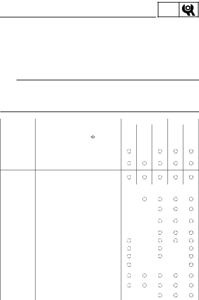
PERIODIC CHECKS AND ADJUSTMENTS
INTRODUCTION
This chapter includes all information necessary to perform recommended checks and adjustments. These preventive maintenance procedures, if followed, will ensure more reliable vehicle operation and a longer service life. The need for costly overhaul work will be greatly reduced. This information applies to vehicles already in service as well as to new vehicles that are being prepared for sale. All service technicians should be familiar with this entire chapter.
PERIODIC MAINTENANCE/LUBRICATION
NOTE:
•For ATVs not equipped with an odometer or an hour meter, follow the month maintenance intervals.
•For ATVs equipped with an odometer or an hour meter, follow the km (mi) or hours maintenance intervals. However, keep in mind that if the ATV isn’t used for a long period of time, the month maintenance intervals should be followed.
|
|
|
|
|
INITIAL |
|
EVERY |
|
|
|
|
|
|
|
|
|
|
|
|
Whichever |
month |
1 |
3 |
6 |
6 |
12 |
ITEM |
ROUTINE |
comes first |
km |
320 |
1,200 |
2,400 |
2,400 |
4,800 |
|
|
|
(mi) |
(200) |
(750) |
(1,500) |
(1,500) |
(3,000) |
|
|
|
|
|
|
|
|
|
|
|
|
hours |
20 |
75 |
150 |
150 |
300 |
|
|
|
|
|
|
|
|
|
Valves* |
• Check valve clearance. |
|
|
|
|
|
|
|
• Adjust if necessary. |
|
|
|
|
|
|
|
|
|
|
|
|
|
|
|
|
|
|
|
|
|
|
|
|
|
|
|
• Check coolant leakage. |
|
|
|
|
|
|
|
Cooling system |
• Repair if necessary. |
|
|
|
|
|
|
|
•Replace coolant every 24 months.
•Check condition.
Spark plug |
• Adjust gap and clean. |
|
|
|
|
|
|
|
• Replace if necessary. |
|
|
|
|
|
|
|
|
|
|
||||
Air filter element |
• Clean. |
|
Every 20–40 hours |
||||
• Replace if necessary. |
(More often in wet or dusty areas.) |
||||||
|
|||||||
|
|
|
|
|
|
|
|
Carburetor* |
• Check starter (choke). |
|
|
|
|
|
|
• Adjust engine idling speed. |
|
|
|
|
|
||
|
|
|
|
|
|
||
|
|
|
|
|
|
|
|
Crankcase breather |
• Check breather hose for cracks or damage. |
|
|
|
|
|
|
system* |
• Replace if necessary. |
|
|
|
|
|
|
|
|
|
|
|
|
|
|
|
• Check for leakage. |
|
|
|
|
|
|
Exhaust system* |
• Tighten if necessary. |
|
|
|
|
|
|
|
• Replace gasket(s) if necessary. |
|
|
|
|
|
|
|
|
|
|
|
|
|
|
Fuel line* |
• Check fuel hose for cracks or damage. |
|
|
|
|
|
|
• Replace if necessary. |
|
|
|
|
|
||
|
|
|
|
|
|
||
|
|
|
|
|
|
|
|
Engine oil |
• Replace. (Warm engine before draining.) |
|
|
|
|
|
|
|
|
|
|
|
|
|
|
Engine oil filter car- |
• Replace. |
|
|
|
|
|
|
tridge |
|
|
|
|
|
||
|
|
|
|
|
|
||
|
|
|
|
|
|
|
|
Engine oil strainer* |
• Clean. |
|
|
|
|
|
|
|
|
|
|
|
|
|
|
Final gear oil |
• Check for oil leakage. |
|
|
|
|
|
|
Differential gear oil |
• Replace every 12 months. |
|
|
|
|
|
|
|
|
|
|
|
|
|
|
Front brake* |
• Check operation/fluid leakage. (See NOTE page 19.) |
|
|
|
|
|
|
• Correct if necessary. |
|
|
|
|
|
||
|
|
|
|
|
|
||
|
|
|
|
|
|
|
|
Rear brake* |
• Check operation/fluid leakage. (See NOTE page 19.) |
|
|
|
|
|
|
• Adjust if necessary. |
|
|
|
|
|
||
|
|
|
|
|
|
||
|
|
|
|
|
|
|
|
Select lever safety |
• Check operation. |
|
|
|
|
|
|
system cable* |
• Adjust if necessary. |
|
|
|
|
|
|
|
|
|
|
|
|
|
|
– 18 –

|
|
|
|
|
|
|
|
|
|
|
|
|
|
PERIODIC MAINTENANCE/LUBRICATION |
|
|
CHK |
|
|
||||||
|
|
|
ADJ |
|
|
|||||||
|
|
|
|
|
|
|
|
|
|
|
|
|
|
|
|
|
|
|
INITIAL |
|
|
|
EVERY |
||
|
|
|
|
|
|
|
|
|
|
|
||
|
|
|
Whichever |
month |
1 |
3 |
6 |
6 |
|
12 |
||
ITEM |
ROUTINE |
|
comes first |
km |
320 |
1,200 |
2,400 |
2,400 |
4,800 |
|||
|
|
|
|
(mi) |
(200) |
(750) |
(1,500) |
(1,500) |
(3,000) |
|||
|
|
|
|
|
|
|
|
|
|
|
||
|
|
|
|
hours |
20 |
75 |
150 |
150 |
|
300 |
||
|
|
|
|
|
|
|
|
|
|
|
|
|
V-belt* |
• Check operation. |
|
|
|
|
|
|
|
|
|
|
|
• Check for cracks or damage. |
|
|
|
|
|
|
|
|
|
|
||
|
|
|
|
|
|
|
|
|
|
|
||
|
|
|
|
|
|
|
|
|
|
|
||
Wheels* |
• Check balance/damage/runout. |
|
|
|
|
|
|
|
|
|
||
• Repair if necessary. |
|
|
|
|
|
|
|
|
|
|
||
|
|
|
|
|
|
|
|
|
|
|
||
|
|
|
|
|
|
|
|
|
|
|||
Wheel bearing* |
• Check bearing assemblies for looseness/damage. |
|
|
|
|
|
|
|
|
|||
• Replace if damaged. |
|
|
|
|
|
|
|
|
|
|
||
|
|
|
|
|
|
|
|
|
|
|
||
|
|
|
|
|
|
|
|
|
|
|
|
|
Front and rear |
• Check operation. |
|
|
|
|
|
|
|
|
|
|
|
suspension* |
• Correct if necessary. |
|
|
|
|
|
|
|
|
|
|
|
|
|
|
|
|
|
|
|
|
|
|
||
Steering system* |
• Check operation./Replace if damaged. |
|
|
|
|
|
|
|
|
|
||
• Check toe-in./Adjust if necessary. |
|
|
|
|
|
|
|
|
|
|||
|
|
|
|
|
|
|
|
|
|
|||
|
|
|
|
|
|
|
|
|
|
|
|
|
Rear upper and |
|
|
|
|
|
|
|
|
|
|
|
|
lower knuckle piv- |
• Lubricate with lithium-soap-based grease. |
|
|
|
|
|
|
|
|
|
||
ots* |
|
|
|
|
|
|
|
|
|
|
|
|
|
|
|
|
|
|
|
|
|
|
|
||
Drive shaft universal |
• Lubricate with lithium-soap-based grease. |
|
|
|
|
|
|
|
|
|
||
joint* |
|
|
|
|
|
|
|
|
|
|
|
|
Engine mount* |
• Check for cracks or damage. |
|
|
|
|
|
|
|
|
|
|
|
|
|
|
|
|
|
|
|
|
|
|
|
|
Front and rear axle |
• Check operation. |
|
|
|
|
|
|
|
|
|
|
|
boots* |
• Replace if damaged. |
|
|
|
|
|
|
|
|
|
|
|
|
|
|
|
|
|
|
|
|
|
|
|
|
Stabilizer bushes* |
• Check for cracks or damage. |
|
|
|
|
|
|
|
|
|
|
|
|
|
|
|
|
|
|
|
|
|
|
||
Fittings and fasten- |
• Check all chassis fittings and fasteners. |
|
|
|
|
|
|
|
|
|
||
ers* |
• Correct if necessary. |
|
|
|
|
|
|
|
|
|
|
|
|
|
|
|
|
|
|
|
|
|
|
|
|
Lights and switches* |
• Check operation. |
|
|
|
|
|
|
|
|
|
|
|
|
• Adjust headlight beams. |
|
|
|
|
|
|
|
|
|
|
|
*Since these items require special tools, data and technical skills, have a Yamaha dealer perform the service.
NOTE:
•Recommended brake fluid: DOT 4
•Brake fluid replacement:
1.When disassembling the master cylinder or caliper, replace the brake fluid. Normally check the brake fluid level and add fluid as required.
2.On the inner parts of the master cylinder and caliper, replace the oil seals every two years.
3.Replace the brake hoses every four years, or if cracked or damaged.
 WARNING
Indicates a potential hazard that could result in serious injury or death.
– 19 –

SEAT, CARRIERS, FENDERS AND FUEL TANK
SEAT, CARRIERS, FENDERS AND FUEL TANK
FRONT CARRIER, FRONT BUMPER AND FRONT FENDER
CHK ADJ
Order |
Job/Part |
Q’ty |
Remarks |
|
|
|
|
|
Removing the front carrier, front |
|
Remove the parts in the order below. |
|
bumper and front fender |
|
|
|
Seat and fuel tank side panels |
|
Refer to “SEAT AND SIDE PANELS” in |
|
|
|
chapter 3. (Manual No.: 5TE2-AE1) |
1 |
Front carrier |
1 |
|
2 |
Front fender panel |
1 |
|
3 |
Engine skid plate |
1 |
|
4 |
Front bumper |
1 |
|
5 |
Front bumper cover |
2 |
|
6 |
Headlight coupler |
2 |
Disconnect. |
7 |
Main switch coupler |
1 |
Disconnect. |
8 |
Handlebar cover |
1 |
|
9 |
Fuel tank cover |
1 |
|
|
|
|
|
– 20 –
CHK
SEAT, CARRIERS, FENDERS AND FUEL TANK ADJ
Order |
Job/Part |
Q’ty |
Remarks |
|
|
|
|
10 |
Auxiliary DC jack connector |
2 |
Disconnect. |
11 |
Indicator light assembly coupler/meter |
3 |
Disconnect. |
|
light coupler |
|
|
12 |
Sub-wire harness 1 coupler |
1 |
Disconnect. |
13 |
Speedometer cable |
1 |
Disconnect. |
14 |
Fan motor breather hose |
1 |
|
15 |
Coolant reservoir breather hose |
1 |
|
16 |
Differential gear case breather hose |
1 |
|
17 |
Front fender |
1 |
|
|
|
|
For installation, reverse the removal pro- |
|
|
|
cedure. |
|
|
|
|
– 21 –

ADJUSTING THE REAR BRAKE
CHASSIS
CHK ADJ
ADJUSTING THE REAR BRAKE
 WARNING
Always adjust both the brake pedal and the rear brake lever whenever adjusting the rear brake.
1.Check:
•rear brake lever free play a Out of specification → Adjust.
Rear brake lever free play 0.5 ~ 2.0 mm (0.02 ~ 0.08 in)
2.Check:
•rear brake pedal height a Out of specification → Adjust.
Rear brake pedal height
67 ~ 77 mm (2.64 ~ 3.03 in)
1 Brake pedal
2 Footrest bracket
3.Adjust:
•rear brake lever free play
•rear brake pedal height
▼▼▼▼▼▼▼▼▼▼▼▼▼▼▼▼▼▼▼▼▼▼▼▼▼▼▼▼▼▼▼▼
a.Loosen the locknut (handlebar) 1 and fully screw in the brake lever cable adjuster (handlebar) 2.
b.Remove the rear brake master cylinder cover 3.
– 22 –
Loading...