


SUPPLEMENTARY SERVICE MANUAL
VK10W
LIT-12618-02-57 |
8GS-28197-10 |
FOREWORD
This Supplementary Service Manual has been prepared to introduce new service and new data for the VK10W. For complete information, on service procedures, it is necessary to use this Supplementary Service Manual together with following manual:
RS90K, RS90RK, RSG90K, RS90MK, RST90K, RST90TFK SERVICE MANUAL: 8FJ-28197-10 (981096) (LIT-12618-02-38)
VK10L SUPPLEMENTARY SERVICE MANUAL: 8FN-28197-10 (LIT-12618-02-42)
VK10W
SUPPLEMENTARY SERVICE MANUAL ©2006 by Yamaha Motor Corporation, U.S.A.
1st Edition, July 2006
All rights reserved. Any reprinting or unauthorized use without the written permission of Yamaha Motor Corporation, U.S.A. is expressly prohibited.
Printed in U.S.A.
P/N.LIT-12618-02-57

NOTICE
This manual was written by the Yamaha Motor Company primarily for use by Yamaha dealers and their qualified mechanics. It is not possible to put an entire mechanic’s education into one manual, so it is assumed that persons using this book to perform maintenance and repairs on Yamaha snowmobiles have a basic understanding of the mechanical concepts and procedures inherent in snowmobile repair. Without such knowledge, attempted repairs or service to this model may render it unfit and/or unsafe to use.
This model has been designed and manufactured to perform within certain specifications in regard to performance and emissions. Proper service with the correct tools is necessary to ensure that the vehicle will operate as designed. If there is any question about a service procedure, it is imperative that you contact a Yamaha dealer for any service information changes that apply to this model. This policy is intended to provide the customer with the most satisfaction from his vehicle and to conform to federal environmental quality objectives.
Yamaha Motor Company, Ltd. is continually striving to improve all models manufactured by Yamaha. Modifications and significant changes in specifications or procedures will be forwarded to all authorized Yamaha dealers and will, where applicable, appear in future editions of this manual.
HOW TO USE THIS MANUAL
Particularly important information is distinguished in this manual by the following notations:
The Safety Alert Symbol means ATTENTION! BE ALERT! YOUR SAFETY IS INVOLVED!
 WARNING Failure to follow WARNING instructions could result in severe injury or death to the snowmobile operator, a bystander, or a person inspecting or repairing the snowmobile.
CAUTION: A CAUTION indicates special precautions that must be taken to avoid damage to the snowmobile.
NOTE: A NOTE provides key information that can make procedures easier or clearer.
MANUAL FORMAT
All of the procedures in this manual are organized in a sequential, step-by-step format. The information has been compiled to provide the mechanic with an easy to read, handy reference that contains comprehensive explanations of all inspection, repair, assembly, and disassembly operations.
In this revised format, the condition of a faulty component will precede an arrow symbol and the course of action required to correct the problem will follow the symbol, e.g.,
•Bearings
Pitting/damage → Replace.
EXPLODED DIAGRAM
Each chapter provides exploded diagrams before each disassembly section to facilitate correct disassembly and assembly procedures.
1 |
2 |
|
|
GEN |
|
INSP |
|
INFO |
|
ADJ |
|
3 |
4 |
|
|
CHAS |
|
POWR |
|
|
TR |
|
|
|
|
|
|
5 |
6 |
|
|
ENG |
|
COOL |
|
7 |
8 |
|
|
CARB |
|
ELEC – |
+ |
9 |
|
|
|
SPEC |
|
|
|
0 |
A |
B |
|
|
|
T |
|
|
|
. |
|
|
|
R |
|
|
|
. |
|
C |
D |
E |
|
F |
G |
H |
|
|
LT |
5 |
|
I |
J |
K |
|
E |
G |
M |
|
L |
M |
N |
|
B |
LS |
M |
|
O |
|
|
|
New |
|
|
|
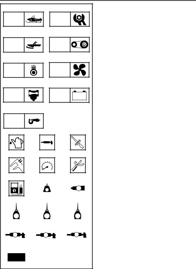
ILLUSTRATED SYMBOLS (Refer to the illustration)
Illustrated symbols 1 to 9 are designed as thumb tabs to indicate the chapter’s number and content.
1General information
2Periodic inspection and adjustment
3Chassis
4Power train
5Engine
6Cooling system
7Carburetion
8Electrical
9Specifications
Illustrated symbols 0 to F are used to identify the specifications which appear.
0 Filling fluid
ALubricant
BTightening
CWear limit, clearance
DEngine speed
ESpecial tool
FΩ, V, A
Illustrated symbols G to O in the exploded diagram indicate grade of lubricant and location of lubrication point.
GApply locking agent (LOCTITE®)
HApply Yamabond No.5®
IApply engine oil
JApply gear oil
KApply molybdenum disulfide oil
LApply wheel bearing grease
MApply low-temperature lithium-soap base grease
NApply molybdenum disulfide grease
OUse new one

INDEX
GENERAL INFORMATION |
GEN |
1 |
|
INFO |
PERIODIC INSPECTION AND ADJUSTMENT
INSPADJ |
2 |
CHASSIS
POWER TRAIN
ENGINE
COOLING SYSTEM
CARBURETION
ELECTRICAL
CHAS 3
POWR 4 TR
ENG 5
COOL 6
CARB 7
–+
ELEC 8
SPECIFICATIONS
SPEC 9

GENERAL INFORMATION |
|
SPECIAL TOOLS ................................................. |
1 |
FOR ELECTRICAL SERVICE ........................ |
1 |
PERIODIC INSPECTION AND |
|
ADJUSTMENT |
|
INTRODUCTION................................................... |
2 |
PERIODIC MAINTENANCE CHART FOR |
|
THE EMISSION CONTROL SYSTEM.................. |
2 |
GENERAL MAINTENANCE AND |
|
LUBRICATION CHART........................................ |
3 |
POWER TRAIN..................................................... |
5 |
DRIVE V-BELT ............................................... |
5 |
BRAKE PAD INSPECTION ............................ |
7 |
AIR BLEEDING (HYDRAULIC BRAKE |
|
SYSTEM) ........................................................ |
7 |
DRIVE CHAIN................................................. |
8 |
TUNING .............................................................. |
11 |
CLUTCH ....................................................... |
11 |
GEAR SELECTION ...................................... |
12 |
HIGH ALTITUDE TUNING............................ |
18 |
POWER TRAIN |
|
SHIFT LEVER..................................................... |
19 |
INSTALLATION ............................................ |
21 |
DRIVE CHAIN HOUSING ................................... |
22 |
REMOVAL .................................................... |
25 |
INSPECTION ................................................ |
25 |
INSTALLATION ............................................ |
27 |
SECONDARY SHAFT ........................................ |
29 |
SECONDARY SHAFT AND DRIVE CHAIN |
|
HOUSING INSTALLATION........................... |
29 |
BRAKE ............................................................... |
31 |
BRAKE PAD REPLACEMENT ..................... |
32 |
BRAKE CALIPER DISASSEMBLY ............... |
36 |
BRAKE CALIPER INSTALLATION............... |
36 |
FRONT AXLE AND TRACK............................... |
37 |
INSTALLATION ............................................ |
37 |
ENGINE |
|
CAMSHAFTS..................................................... |
38 |
INSTALLATION............................................ |
38 |
CARBURETION |
|
CARBURETORS ............................................... |
43 |
THROTTLE POSITION SENSOR (T.P.S.) |
|
INSPECTION AND ADJUSTMENT ............. |
44 |
ELECTRICAL |
|
SIGNAL SYSTEM .............................................. |
46 |
CIRCUIT DIAGRAM..................................... |
46 |
TROUBLESHOOTING ................................. |
48 |
GEAR POSITION SWITCH.......................... |
49 |
GEAR POSITION SWITCH RELAY............. |
49 |
SPECIFICATIONS |
|
GENERAL SPECIFICATIONS........................... |
50 |
MAINTENANCE SPECIFICATIONS.................. |
52 |
ENGINE ....................................................... |
52 |
POWER TRAIN............................................ |
57 |
CHASSIS ..................................................... |
60 |
ELECTRICAL ............................................... |
61 |
HIGH ALTITUDE SETTINGS....................... |
64 |
TIGHTENING TORQUE..................................... |
66 |
ENGINE ....................................................... |
66 |
POWER TRAIN............................................ |
68 |
CHASSIS ..................................................... |
70 |
GENERAL TORQUE SPECIFICATIONS .......... |
71 |
DEFINITION OF UNITS ..................................... |
71 |
CABLE ROUTING ............................................. |
72 |
GEN
SPECIAL TOOLS INFO 

GENERAL INFORMATION
SPECIAL TOOLS
Some special tools are necessary for a completely accurate tune-up and assembly. Using the correct special tool will help prevent damage that can be caused by the use of improper tools or improvised techniques.
NOTE:
•Be sure to use the correct part number when ordering the tool, since the part number may differ according to country.
•For USA and Canada, use part number starting with “YB-”, “YM-”, “YU-” or “YS-”, “ACC-”.
•For others, use part number starting with “90890-”.
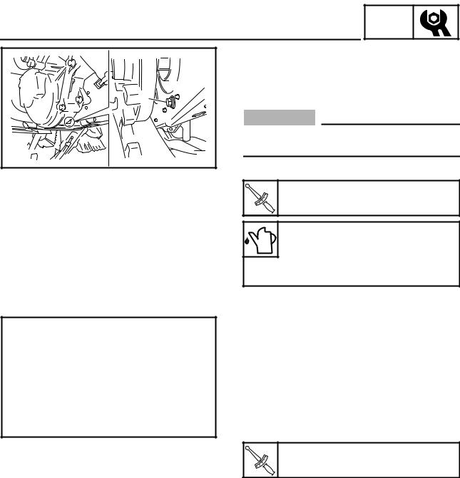
FOR ELECTRICAL SERVICE
• Pocket tester P/N: YU-03112-C
90890-03112
This instrument is necessary for checking the electrical components.
1 |
1

INTRODUCTION/PERIODIC MAINTENANCE CHART FOR THE EMISSION CONTROL SYSTEM
INSP ADJ
PERIODIC INSPECTION AND ADJUSTMENT
INTRODUCTION
This chapter includes all information necessary to perform recommended inspections and adjustments. These preventive maintenance procedures, if followed, will ensure more reliable machine operation and a longer service life. In addition, the need for costly overhaul work will be greatly reduced. This information applies to machines already in service as well as new machines that are being prepared for sale. All service technicians should be familiar with this entire chapter.
PERIODIC MAINTENANCE CHART FOR THE EMISSION CONTROL SYSTEM
|
|
|
Initial |
Every |
|
|
Pre-opera- |
1 month or |
Seasonally |
Item |
Remarks |
tion check |
800 km |
or 4,000 km |
|
|
(Daily) |
(500 mi) |
(2,500 mi) |
|
|
|
(40 hr) |
(200 hr) |
|
|
|
|
|
|
Check condition. |
|
|
|
Spark plugs |
Adjust gap and clean. |
|
|
|
|
Replace if necessary. |
|
|
|
|
|
|
|
|
Valve clearance |
Check clearance. |
Every 40,000 km (25,000 mi) |
|
|
Adjust clearance when engine is cold. |
|
|||
|
|
|
|
|
|
|
|
|
|
Crankcase breather system |
Check breather hose for cracks or damage. |
|
|
|
Replace if necessary. |
|
|
|
|
|
|
|
|
|
|
|
|
|
|
Fuel filter |
Check condition. |
|
|
|
Replace if necessary. |
|
|
|
|
|
|
|
|
|
|
|
|
|
|
Fuel line |
Check fuel hose for cracks or damage. |
|
|
|
Replace if necessary. |
|
|
|
|
|
|
|
|
|
|
|
|
|
|
Idle speed |
Check and adjust engine idle speed. |
|
|
|
|
|
|
|
|
|
Adjust synchronization of carburetors. |
|
|
|
Carburetors |
|
|
|
|
Adjust the jets. |
Whenever operating condition (elevation/ |
|||
|
temperature) is changed. |
|
||
|
|
|
||
|
|
|
|
|
Exhaust system |
Check for leakage. |
|
|
|
Tighten or replace gasket if necessary. |
|
|
|
|
|
|
|
|
|
|
|
|
|
|
2

|
|
|
|
|
|
|
|
|
GENERAL MAINTENANCE AND LUBRICATION CHART |
|
|
INSP |
|
||||
|
|
ADJ |
|
|
||||
GENERAL MAINTENANCE AND LUBRICATION CHART |
|
|
|
|
|
|
||
|
|
|
|
|
|
|||
|
|
|
|
|
|
|
|
|
|
|
|
|
|
Initial |
|
|
Every |
|
|
Pre-opera- |
1 month or |
|
Seasonally |
|||
Item |
Remarks |
tion check |
|
|
800 km |
|
or 4,000 km |
|
|
|
(Daily) |
|
(500 mi) |
|
|
(2,500 mi) |
|
|
|
|
|
|
(40 hr) |
|
|
(200 hr) |
|
|
|
|
|
|
|
|
|
Engine oil |
Check oil level. |
|
|
|
|
|
|
|
|
|
|
|
|
|
|
|
|
Replace. |
|
|
|
|
|
|
|
|
|
|
|
|
|
|
|
|
|
|
|
|
|
|
|
|
|
|
|
|
|
|
|
|
|
Every |
|
Engine oil filter cartridge |
Replace. |
|
|
|
|
|
20,000 km |
|
|
|
|
|
|
|
|
(12,000 mi) |
|
|
|
|
|
|
|
|
|
|
Fuel |
Check fuel level. |
|
|
|
|
|
|
|
|
|
|
|
|
|
|
|
|
Engine coolant |
Check coolant level. |
|
|
|
|
|
|
|
|
|
|
|
|
|
|
|
|
Air bleed the cooling system if necessary. |
|
|
|
|
|
|
|
|
|
|
|
|
|
|
|
|
|
|
|
|
|
|
|
|
|
|
Louvers |
Check condition. |
|
|
|
|
|
|
|
Remove snow if necessary. |
|
|
|
|
|
|
|
|
|
|
|
|
|
|
|
|
|
|
|
|
|
|
|
|
|
|
Throttle lever (carburetor |
Check throttle lever operation. |
|
|
|
|
|
|
|
side) |
|
|
|
|
|
|
|
|
|
|
|
|
|
|
|
|
|
|
|
|
|
|
|
|
|
|
Throttle lever (handlebar |
Check operation. |
|
|
|
|
|
|
|
side) |
Repair if necessary. |
|
|
|
|
|
|
|
|
|
|
|
|
|
|
|
|
Throttle override system |
Check operation. |
|
|
|
|
|
|
|
(T.O.R.S.) |
Repair if necessary. |
|
|
|
|
|
|
|
|
|
|
|
|
|
|
|
|
Engine stop switch |
Check operation. |
|
|
|
|
|
|
|
Repair if necessary. |
|
|
|
|
|
|
|
|
|
|
|
|
|
|
|
|
|
|
|
|
|
|
|
|
|
|
Drive guard |
Check for cracks, bends or damage. |
|
|
|
|
|
|
|
Replace if necessary. |
|
|
|
|
|
|
|
|
|
|
|
|
|
|
|
|
|
|
|
|
|
|
|
|
|
|
V-belt |
Check for wear and damage. |
|
|
|
|
|
|
|
Replace if necessary. |
|
|
|
|
|
|
|
|
|
|
|
|
|
|
|
|
|
|
|
|
|
|
|
|
|
|
Drive track and idler wheels |
Check deflection, and for wear and damage. |
|
|
|
|
|
|
|
Adjust/replace if necessary. |
|
|
|
|
|
|
|
|
|
|
|
|
|
|
|
|
|
|
|
|
|
|
|
|
|
|
Slide runners |
Check for wear and damage. |
|
|
|
|
|
|
|
|
|
|
|
|
|
|
|
|
Replace if necessary. |
|
|
|
|
|
|
|
|
|
|
|
|
|
|
|
|
|
|
|
|
|
|
|
|
|
|
|
Check operation and fluid leakage. |
|
|
|
|
|
|
|
|
|
|
|
|
|
|
|
|
Brake and parking brake |
Adjust free play and/or replace pads if necessary. |
|
|
|
|
|
|
|
|
|
|
|
|
||||
|
Replace brake fluid. |
See NOTE on page 4. |
||||||
|
|
|
|
|
|
|
|
|
|
Check for slight free play. |
|
|
|
|
|
Every |
|
Disc brake installation |
|
|
|
|
|
1,600 km |
||
Lubricate shaft with specified grease as required. |
|
|
|
|
|
|||
|
|
|
|
|
|
(1,000 mi) |
||
|
|
|
|
|
|
|
||
|
|
|
|
|
|
|
|
|
Drive chain oil |
Check oil level. |
|
|
|
|
|
|
|
|
|
|
|
|
|
|
|
|
Replace. |
|
|
|
|
|
|
|
|
|
|
|
|
|
|
|
|
|
|
|
|
|
|
||||
Drive chain |
Check deflection. |
Initial at 500 km (300 mi) and every 800 km |
||||||
Adjust if necessary. |
(500 mi) thereafter. |
|
|
|||||
|
|
|
||||||
|
|
|
|
|
|
|
|
|
Skis and ski runners |
Check for wear and damage. |
|
|
|
|
|
|
|
|
|
|
|
|
|
|
|
|
Replace if necessary. |
|
|
|
|
|
|
|
|
|
|
|
|
|
|
|
|
|
|
|
|
|
|
|
|
|
|
Steering system |
Check operation. |
|
|
|
|
|
|
|
|
|
|
|
|
|
|
|
|
Adjust toe-out if necessary. |
|
|
|
|
|
|
|
|
|
|
|
|
|
|
|
|
|
|
|
|
|
|
|
|
|
|
Strap |
Check for damage. |
|
|
|
|
|
|
|
Replace if necessary. |
|
|
|
|
|
|
|
|
|
|
|
|
|
|
|
|
|
|
|
|
|
|
|
|
|
|
Lights |
Check operation. |
|
|
|
|
|
|
|
Replace bulbs if necessary. |
|
|
|
|
|
|
|
|
|
|
|
|
|
|
|
|
|
|
|
|
|
|
|
|
|
|
Battery |
Check condition. |
|
|
|
|
|
|
|
Charge if necessary. |
|
|
|
|
|
|
|
|
|
|
|
|
|
|
|
|
|
|
|
|
|
|
|
|
|
|
|
Check engagement and shift speed. |
|
|
|
|
|
|
|
|
Adjust if necessary. |
Whenever operating elevation is changed. |
||||||
|
|
|
|
|
|
|
|
|
Primary and secondary |
Inspect sheaves for wear/damage. |
|
|
|
|
|
|
|
Inspect weights/rollers and bushings for wear-for pri- |
|
|
|
|
|
|
|
|
clutches |
mary. |
|
|
|
|
|
|
|
|
Inspect ramp shoes/bushings for wear-for secondary. |
|
|
|
|
|
|
|
|
Replace if necessary. |
|
|
|
|
|
|
|
|
|
|
|
|
|
|
|
|
|
Lubricate with specified grease. |
|
|
|
|
|
|
|
3
2 |
|
|
|
|
|
|
|
|
|
|
GENERAL MAINTENANCE AND LUBRICATION CHART |
|
|
INSP |
|
|
|
|||
|
|
ADJ |
|
|
|
||||
|
|
|
|
|
|
|
|
|
|
|
|
|
|
|
Initial |
|
Every |
||
|
|
Pre-opera- |
1 month or |
|
Seasonally |
||||
Item |
Remarks |
tion check |
|
|
800 km |
or 4,000 km |
|||
|
|
(Daily) |
|
(500 mi) |
|
(2,500 mi) |
|||
|
|
|
|
|
(40 hr) |
|
(200 hr) |
||
|
|
|
|
|
|
|
|
|
|
Steering column bearing |
Lubricate with specified grease. |
|
|
|
|
|
|
|
|
|
|
|
|
|
|
|
|
|
|
Ski and front suspension |
Lubricate with specified grease. |
|
|
|
|
|
|
|
|
|
|
|
|
|
|
|
|
|
|
Suspension component |
Lubricate with specified grease. |
|
|
|
|
|
|
|
|
|
|
|
|
|
|
|
|
|
|
Parking brake cable end and |
Lubricate with specified grease. |
|
|
|
|
|
|
|
|
|
|
|
|
|
|
|
|
|
|
Check cable damage. |
|
|
|
|
|
|
|
|
|
lever end/throttle cable end |
|
|
|
|
|
|
|
|
|
Replace if necessary. |
|
|
|
|
|
|
|
|
|
|
|
|
|
|
|
|
|
|
|
|
|
|
|
|
|
|
|
|
|
Shroud latches |
Make sure that the shroud latches are hooked. |
|
|
|
|
|
|
|
|
Fittings and fasteners
Check tightness.
Repair if necessary.
Tool kit and recommended
Check for proper placement.
equipment
NOTE:
Brake system:
•After disassembling the master cylinder or caliper cylinder, always change the brake fluid. Regularly check the brake fluid level and add fluid if necessary.
•Replace the oil seals of the master cylinder and caliper cylinder every two years.
•Replace the brake hose every four years, or if cracked or damaged.
4
DRIVE V-BELT
POWER TRAIN
DRIVE V-BELT
 WARNING
INSP ADJ
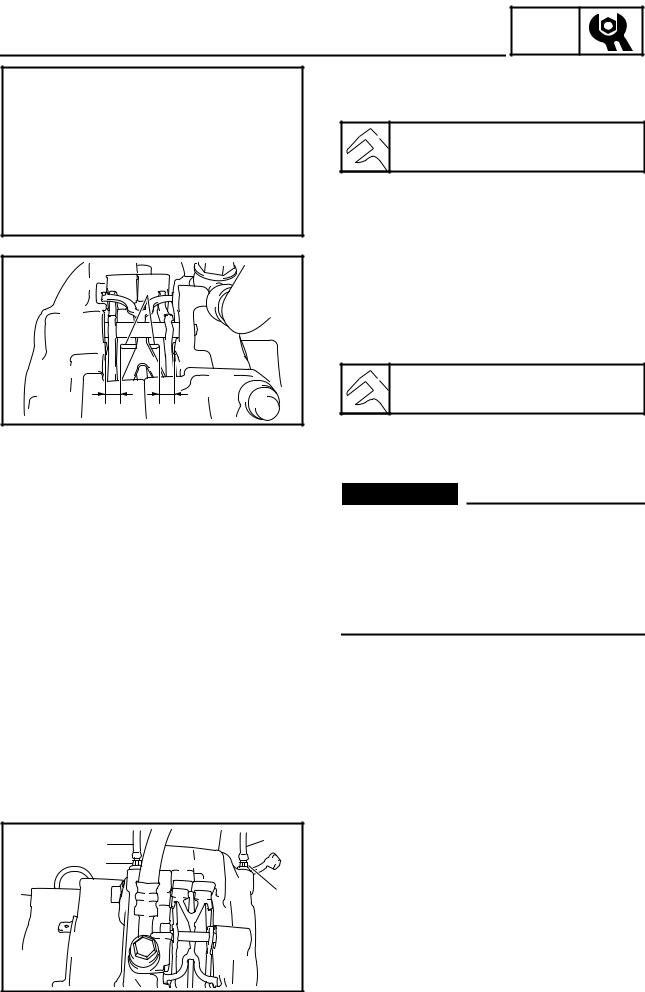
When installing the new V-belt, make sure that it is positioned from 1.5 mm (0.06 in) above the edge of the secondary sheave to –0.5 mm (–0.02 in) below the edge a.
If the V-belt is not positioned correctly, the clutch engagement speed will be changed. The machine may move unexpectedly when the engine is started.
Adjust the V-belt position by removing or adding a spacer 1 on each adjusting bolt 2.
CAUTION:
As the V-belt wears, adjustment may be necessary. To ensure proper clutch performance, the V-belt position should be adjusted by adding a spacer on each adjusting bolt when the V-belt position reaches 1.5 mm (0.06 in) below the edge.
New belt width: 34.1 mm (1.34 in)
Belt wear limit width: 32.1 mm (1.26 in)
1.Measure:
• V-belt position a
NOTE:
Install the new V-belt onto the secondary sheave only. Do not force the V-belt between the sheaves; the sliding and fixed sheaves must touch each other.
Standard V-belt height:
–0.5 ~ 1.5 mm (–0.02 ~ 0.06 in)
5
INSP
DRIVE V-BELT ADJ
2.Adjust the position of the V-belt by removing or adding a spacer 1 on each adjusting bolt 2.
V-belt position |
Adjustment |
|
|
More than 1.5 mm |
|
(0.06 in) above the |
Remove a spacer |
edge |
|
|
|
From 1.5 mm (0.06 in) |
|
above the edge to |
Not necessary |
–0.5 mm (–0.02 in) |
(It is correct.) |
below the edge |
|
|
|
More than –0.5 mm |
|
(–0.02 in) below the |
Add spacer |
edge |
|
|
|
|
|
Part number |
Thickness |
|
|
90201-061H1 |
0.5 mm (0.02 in) |
|
|
90201-06037 |
1.0 mm (0.04 in) |
|
|
3.Tighten:
• Adjusting bolt 2
Adjusting bolt:
10 Nm (1.0 m · kg, 7.2 ft · lb)
T .
R .
4.Inspect:
•Drive V-belt Cracks/damage/wear → Replace.
Oil or grease on the V-belt → Check the primary and secondary sheaves.
5.Inspect:
•Primary sheave
•Secondary sheave
Oil or grease on the primary and secondary sheaves → Use a rag soaked in lacquer thin-
ner or solvent to remove the oil or grease. Check the primary and secondary sheaves.
6
DRIVE V-BELT/BRAKE PAD INSPECTION/ AIR BLEEDING (HYDRAULIC BRAKE SYSTEM)
INSP ADJ
6.Measure:
•Drive V-belt circumference a Out of specification → Replace.
 V-belt circumference:
1,132 ~ 1,138 mm (44.6 ~ 44.8 in)
1
aa
1 1
2
2
BRAKE PAD INSPECTION
1.Apply the brake lever.
2.Inspect:
•Brake pad wear a
Wear indicator 1 nearly contacts the brake disc → Replace as a set.
 Wear limit:
4.7mm (0.19 in)
AIR BLEEDING (HYDRAULIC BRAKE SYSTEM)
 WARNING
Bleed the brake system in the following cases:
•The system has been disassembled.
•A brake hose is loosened or removed.
•The brake fluid has been very low.
•Brake operation is faulty.
If the brake system is not properly bled a loss of braking performance may occur.
1.Bleed:
• Brake system
Air bleeding steps:
a.Fill the brake master cylinder reservoir with the proper brake fluid.
b.Install the diaphragm. Be careful not to spill any fluid or allow the brake master cylinder reservoir to overflow.
c.Connect clear plastic hoses 1 tightly to the brake caliper bleed screws 2.
d.Place the other ends of the hoses in a container.
e.Slowly apply the brake lever several times.
f.Pull the lever in, then hold the lever in position.
g.Loosen the bleed screws and allow the brake lever to travel towards its limit.
h.Tighten the bleed screws when the brake lever limit has been reached, then release the lever.
7
AIR BLEEDING (HYDRAULIC BRAKE SYSTEM)/ DRIVE CHAIN
INSP ADJ
i.Repeat steps (e) to (h) until all of the air bubbles have disappeared from the fluid.
j.Tighten the bleed screws.
Bleed screw:
6 Nm (0.6 m · kg, 4.3 ft · lb)
T .
R .
NOTE:
If bleeding is difficult, it may be necessary to let the brake fluid settle for a few hours.
Repeat the bleeding procedure when the tiny bubbles in the system have disappeared.
k. Add brake fluid to the proper level.
 WARNING
After bleeding the brake system, check the brake operation.
DRIVE CHAIN
Oil level inspection
 WARNING
The engine and muffler will be very hot after the engine has run. Avoid touching a hot engine and muffler while they are still hot with any part of your body or clothing during inspection or repair.
1.Place the machine on a level surface.
2.Check:
• Oil level
8
INSP
DRIVE CHAIN ADJ
 1
1
2
b  a
a
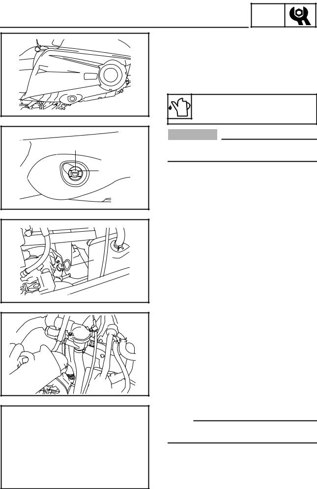
Checking steps:
•Remove the rubber cap 1.
•Check the oil level through the check window 2 located on the drive chain housing.
•If the oil is below the minimum level mark a, remove the dipstick 3 and add sufficient oil to the maximum level mark b.
Recommended oil: Gear oil “GL-3” 75W or 80W
CAUTION:
Make sure that no foreign material enters the drive chain housing.
3
• Reinstall the dipstick 3.
NOTE:
Align the notch c of the dipstick handle with the projection d of the drive chain housing.
• Install the rubber cap.
9
INSP
DRIVE CHAIN ADJ
1 |
Oil replacement
Oil replacement steps:
•Place the oil pan under the drain hole.
•Remove the oil drain bolt (along with the gasket) 1 and drain the oil.
CAUTION:
Be sure to remove any oil from the heat protector.
• Install the new gasket and oil drain bolt 1.
Oil drain bolt:
16 Nm (1.6 m · kg, 11 ft · lb)
T .
R .
Recommended oil: Gear oil “GL-3” 75W or 80W
Oil capacity:
0.35 L (0.31 Imp qt, 0.37 US qt)
Chain slack adjustment
1.Adjust:
• Drive chain slack
Adjustment steps:
•Loosen the locknut 1.
•Turn the adjusting bolt 2 clockwise until it is finger tight, and then loosen it 1/4 turn.
•Hold the adjusting bolt 2 in place while tightening the chain adjusting locknut 1.
Drive chain adjusting locknut: 25 Nm (2.5 m · kg, 18 ft · lb)
T .
R .
10

CLUTCH
TUNING
INSP ADJ
CLUTCH |
|
|
|
|
L |
|
Blue |
|
P |
Pink |
|
High altitude |
|
|
|
|
|
|
|||||
|
|
|
|
|
|
|
|
|
|
||
|
|
|
|
W |
|
White |
|
Y |
Yellow |
||
|
|
|
|
|
|
|
|||||
Specifications |
|
|
|
|
|
|
|
|
|
|
|
|
|
|
|
|
|
|
|
|
|
||
|
|
|
|
|
|
|
|
||||
È Elevation |
~ 800 m |
600 ~ 1,400 m |
1,200 ~ 2,000 m |
|
1,800 ~ 2,600 m |
|
2,400 ~ 3,000 m |
||||
(~ 2,500 ft) |
(2,000 ~ 4,500 ft) |
(4,000 ~ 6,500 ft) |
(6,000 ~ 8,500 ft) |
|
(8,000 ~ 10,000 ft) |
||||||
|
|
||||||||||
|
|
|
|
|
|
|
|
|
|
|
|
É Engine idle speed |
1,400 ± 100 r/min |
← |
← |
|
|
|
← |
|
|
← |
|
|
|
|
|
|
|
|
|
|
|||
Ê Engagement r/min |
Approx. 2,400 r/min |
← |
Approx. 2,500 r/min |
|
|
|
← |
Approx. 2,600 r/min |
|||
|
|
|
|
|
|
|
|
|
|
|
|
Ë Shift r/min |
Approx. 8,500 r/min |
← |
← |
|
|
|
← |
|
|
← |
|
|
|
|
|
|
|
|
|
|
|
|
|
Ì Main jet |
|
|
|
|
|
|
|
|
|
|
|
|
|
|
|
|
|||||||
Í Pilot jet |
, Refer to “HIGH ALTITUDE SETTINGS” in “MAINTENANCE SPECIFICATIONS”. |
|
|
|
|||||||
|
|
|
|
|
|
|
|
|
|
|
|
Î Pilot screw |
|
|
|
|
|
|
|
|
|
|
|
|
|
|
|
|
|
|
|
|
|
|
|
Ï Secondary reduc- |
|
|
|
|
|
|
|
|
|
|
|
tion ratio (number |
20/39 (68 L) |
← |
19/39 (68 L) |
|
|
|
← |
|
|
← |
|
of links) |
|
|
|
|
|
|
|
|
|
|
|
|
|
|
|
|
|
|
|
|
|
|
|
Ð Primary sheave |
90501-550A2 |
← |
← |
|
|
|
← |
90501-580A1 |
|||
spring |
|
|
|
||||||||
|
|
|
|
|
|
|
|
|
|
||
|
|
|
|
|
|
|
|
|
|
||
Ñ Color |
W-L-W |
← |
← |
|
|
|
← |
L-Y-L |
|
||
|
|
|
|
|
|
|
|
|
|||
Ò Free length |
82.3 mm (3.24 in) |
← |
← |
|
|
|
← |
81.4 mm (3.20 in) |
|||
|
|
|
|
|
|
|
|
|
|
|
|
Ó Preload |
196 N (20 kg, 44 lb) |
← |
← |
|
|
|
← |
|
|
← |
|
|
|
|
|
|
|
|
|
|
|||
|
22.1 N/mm |
|
|
|
|
|
|
24.5 N/mm |
|||
Ô Spring rate |
(2.25 kg/mm, |
← |
← |
|
|
|
← |
(2.5 kg/mm, |
|||
|
126 lb/in) |
|
|
|
|
|
|
140 lb/in) |
|||
|
|
|
|
|
|
|
|
|
|||
Õ Wire diameter |
5.5 mm (0.217 in) |
← |
← |
|
|
|
← |
5.8 mm (0.228 in) |
|||
|
|
|
|
|
|
|
|
|
|
|
|
Ö Outside diameter |
59.5 mm (2.34 in) |
← |
← |
|
|
|
← |
|
|
← |
|
|
|
|
|
|
|
|
|
|
|
|
|
× Weight (ID) |
8FN-17605-00 |
← |
← |
|
|
|
← |
|
|
← |
|
(8FN00) |
|
|
|
|
|
||||||
|
|
|
|
|
|
|
|
|
|
||
|
|
|
|
|
|
|
|
||||
|
Steel 17.2 (OUT) |
Steel 17.2 with hole |
Steel 13.3 with hole |
Aluminum 13.3 with |
None (OUT) |
||||||
|
(OUT) |
(OUT) |
hole (OUT) |
||||||||
Ø Weight rivet |
|
|
|
|
|||||||
|
|
|
|
|
|
|
|
|
|
||
Steel 17.2 with hole |
Steel 17.2 with hole |
Steel 13.3 with hole |
Aluminum 13.3 with |
None (IN) |
|||||||
|
|||||||||||
|
(IN) |
(IN) |
(IN) |
hole (IN) |
|
||||||
|
|
|
|
|
|||||||
|
|
|
|
|
|
|
|
|
|
|
|
Ù Weight bushing |
VESPEL TP-8549 |
← |
← |
|
|
|
← |
|
|
← |
|
|
|
|
|
|
|
|
|
|
|
|
|
Ú Roller outer dia. |
15.6 mm (0.61 in) |
← |
← |
|
|
|
← |
|
|
← |
|
|
|
|
|
|
|
|
|
|
|
|
|
Û Roller bushing |
VESPEL TP-8549 |
← |
← |
|
|
|
← |
|
|
← |
|
|
|
|
|
|
|
|
|
|
|
|
|
Ü Pri. clutch shim |
None |
← |
← |
|
|
|
← |
|
|
← |
|
|
|
|
|
|
|
|
|
|
|
|
|
Ý Secondary sheave |
90508-60012 |
← |
← |
|
|
|
← |
|
|
← |
|
spring |
|
|
|
|
|
||||||
|
|
|
|
|
|
|
|
|
|
||
|
|
|
|
|
|
|
|
|
|
|
|
Þ Color |
P |
← |
← |
|
|
|
← |
|
|
← |
|
|
|
|
|
|
|
|
|
|
|
|
|
ß Free length |
75 mm (2.95 in) |
← |
← |
|
|
|
← |
|
|
← |
|
|
|
|
|
|
|
|
|
|
|
|
|
À Preload rate |
60° (3-3) |
← |
← |
|
|
|
← |
|
|
← |
|
1,211 kg · mm/rad |
|
|
|
|
|
||||||
|
|
|
|
|
|
|
|
|
|
||
|
|
|
|
|
|
|
|
|
|
|
|
Á Wire diameter |
6.0 mm (0.236 in) |
← |
← |
|
|
|
← |
|
|
← |
|
|
|
|
|
|
|
|
|
|
|
|
|
+ Outside diameter |
69.5 mm (2.74 in) |
← |
← |
|
|
|
← |
|
|
← |
|
|
|
|
|
|
|
|
|
|
|
|
|
, Sec. torque cam |
39° |
← |
← |
|
|
|
← |
|
|
← |
|
angle |
|
|
|
|
|
||||||
|
|
|
|
|
|
|
|
|
|
||
|
|
|
|
|
|
|
|
|
|
|
|
- Sec. clutch shim |
1.0 mm (0.04 in) |
← |
← |
|
|
|
← |
|
|
← |
|
|
|
|
|
|
|
|
|
|
|
|
|
11

INSP
CLUTCH/GEAR SELECTION ADJ
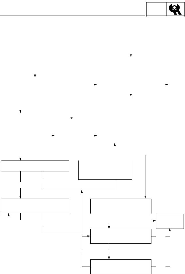
The clutch may require tuning depending upon where the machine will be operated and the desired handling characteristics. The clutch can be tuned by changing the engagement and shifting speeds.
Clutch engagement speed is defined as the engine speed at which the machine first begins to move from a complete stop.
Clutch shifting speed is defined as the engine speed reached when the machine has travelled 800 m (2,500 ft) after being started at full-throttle from a dead stop.
Normally, when a machine reaches shifting speed, the vehicle speed increases but the engine speed remains nearly constant. Under unfavorable conditions (wet snow, icy snow, hills, or rough terrain), however, engine speed may decrease after the shifting speed has been reached.
È Engine speed É Good condition
Ê Clutch shifting speed
Ë Clutch engagement speed Ì Starting position
Í Distance travelled 800 m (2,500 ft)
GEAR SELECTION
The reduction ratio of the driven gear to the drive gear must be set according to the snow conditions. If there are many rough surfaces or unfavorable snow conditions, the drive/driven gear ratio should be increased. If the surfaces are fairly smooth or better snow conditions exist, decrease the ratio.
Gear ratio chart
The drive and driven gears and the chains shown in the gear ratio chart are available as options. The figures containing a decimal point represent the drive/driven gear ratios, while the bottom numbers designate the number of links in the chain.
12
GEAR SELECTION
1 Chain and sprocket part number
INSP ADJ
È Parts name |
É Teeth & links |
|
Ê Parts no. |
|
|
|
|
Ë Standard |
|
|||||||||
|
|
|
|
|
|
|
|
|
|
|
|
|
|
|
|
|
|
|
|
|
|
19 teeth |
|
|
|
8FA-17682-90 |
|
|
|
|
|
|
|
|
|||
|
|
|
|
|
|
|
|
|
|
|
|
|
|
|
|
|
|
|
|
|
|
20 teeth |
|
|
|
8FA-17682-00 |
|
|
|
|
|
|
|
|
|||
|
|
|
|
|
|
|
|
|
|
|
|
|
|
|
|
|
|
|
Ì Drive sprocket |
|
21 teeth |
|
|
|
8FA-17682-10 |
|
|
|
|
|
|
|
|
||||
|
|
|
|
|
|
|
|
|
|
|
|
|
|
|
|
|
||
|
22 teeth |
|
|
|
8FA-17682-20 |
|
|
|
|
|
|
|
|
|||||
|
|
|
|
|
|
|
|
|
|
|
|
|
|
|||||
|
|
|
|
|
|
|
|
|
|
|
|
|
|
|
|
|
|
|
|
|
|
23 teeth |
|
|
|
8FA-17682-30 |
|
|
|
|
|
|
|
|
|||
|
|
|
|
|
|
|
|
|
|
|
|
|
|
|
|
|
|
|
|
|
|
24 teeth |
|
|
|
8FA-17682-40 |
|
|
|
|
|
|
|
|
|||
|
|
|
|
|
|
|
|
|
|
|
|
|
|
|
|
|
|
|
|
|
|
38 teeth |
|
|
|
8FB-47587-80 |
|
|
|
|
|
|
|
|
|||
|
|
|
|
|
|
|
|
|
|
|
|
|
|
|
|
|
|
|
Í Driven sprocket |
|
39 teeth |
|
|
|
8FB-47587-90 |
|
|
|
|
√ |
|
||||||
|
|
|
|
|
|
|
|
|
|
|
|
|
|
|
|
|
|
|
|
|
|
40 teeth |
|
|
|
8FB-47587-00 |
|
|
|
|
|
|
|
|
|||
|
|
|
|
|
|
|
|
|
|
|
|
|
|
|
|
|
|
|
Î Chain |
|
|
68 links |
|
|
|
94890-09068 |
|
|
|
|
√ |
|
|||||
|
|
|
|
|
|
|
|
|
|
|
|
|
|
|
|
|
|
|
|
|
70 links |
|
|
|
94890-09070 |
|
|
|
|
|
|
|
|
||||
|
|
|
|
|
|
|
|
|
|
|
|
|
|
|||||
|
|
|
|
|
|
|
|
|
|
|
|
|
|
|
|
|
|
|
2 Gear ratio |
|
|
|
|
|
|
|
|
|
|
|
|
|
|
|
|
|
|
|
|
|
|
|
|
|
|
|
|
|
|
|
|
|
|
|
|
|
|
È Drive gear |
19 teeth |
|
20 teeth |
|
21 teeth |
|
22 teeth |
23 teeth |
|
24 teeth |
|||||||
É Driven gear |
|
|
|
|
|
|||||||||||||
|
|
|
|
|
|
|
|
|
|
|
|
|
|
|
|
|
||
|
|
|
|
|
|
|
|
|
|
|
|
|
|
|
|
|
|
|
|
38 teeth |
|
|
|
|
|
1.90 |
|
1.81 |
1.73 |
|
1.65 |
|
|
1.58 |
|||
|
|
|
|
|
|
68 links |
|
68 links |
|
|
68 links |
70 links |
|
70 links |
||||
|
|
|
|
|
|
|
|
|
|
|
||||||||
|
|
|
|
|
|
|
|
|
|
|
|
|
|
|
|
|
|
|
|
39 teeth |
|
2.05 |
|
|
1.95 |
|
1.86 |
1.77 |
|
1.70 |
|
|
1.63 |
||||
|
|
68 links |
|
68 links |
|
68 links |
|
|
70 links |
70 links |
|
70 links |
||||||
|
|
|
|
|
|
|
|
|||||||||||
|
|
|
|
|
|
|
|
|
|
|
|
|
|
|
|
|
|
|
|
40 teeth |
|
2.11 |
|
|
2.00 |
|
1.91 |
1.82 |
|
1.74 |
|
|
1.67 |
||||
|
|
68 links |
|
68 links |
|
70 links |
|
|
70 links |
70 links |
|
70 links |
||||||
|
|
|
|
|
|
|
|
|||||||||||
|
|
|
|
|
|
|
|
|
|
|
|
|
|
|
|
|
|
|
3 Secondary sheave spring |
|
|
|
|
|
|
|
|
|
|
|
|
|
|
||||
|
|
|
|
|
|
|
|
|
|
|
|
|
|
|
|
|
||
|
É Spring rate |
Ê Preload |
|
|
|
|
Ì Wire gauge |
|
|
Î Free length |
|
Ï Outside |
|
|
|
|||
È Part No. |
N · mm/rad |
N/mm (kg/mm) |
|
Ë Color |
|
Í No. of coils |
|
|
diameter |
|
Ð Standard |
|||||||
|
(kg · mm/rad) |
(lb/in) |
|
|
|
|
mm (in) |
|
|
|
mm (in) |
|
mm (in) |
|
|
|
||
|
|
|
|
|
|
|
|
|
|
|
|
|
|
|||||
|
|
|
|
|
|
|
|
|
|
|
|
|
|
|
||||
90508-500B1 |
6003 (613) |
6.2 (0.63), 35.28 |
|
Brown |
|
5.0 (0.196) |
5.19 |
|
75 (2.95) |
|
69.5 (2.736) |
|
|
|
||||
|
|
|
|
|
|
|
|
|
|
|
|
|
|
|
||||
90508-536A9 |
7147 (729) |
7.3 (0.74), 41.44 |
|
Red |
|
5.3 (0.209) |
5.53 |
|
75 (2.95) |
|
69.5 (2.736) |
|
|
|
||||
|
|
|
|
|
|
|
|
|
|
|
|
|
|
|
||||
90508-556A2 |
8314 (848) |
8.5 (0.87), 48.72 |
|
Green |
|
5.5 (0.217) |
5.53 |
|
75 (2.95) |
|
69.5 (2.736) |
|
|
|
||||
|
|
|
|
|
|
|
|
|
|
|
|
|
|
|
||||
90508-556A7 |
9460 (965) |
10.2 (1.04), 58.24 |
|
Silver |
|
5.5 (0.217) |
4.86 |
|
75 (2.95) |
|
69.5 (2.736) |
|
|
|
||||
|
|
|
|
|
|
|
|
|
|
|
|
|
|
|
||||
90508-60012 |
11876 (1211) |
12.3 (1.26), 70.56 |
|
Pink |
|
6.0 (0.236) |
5.53 |
|
75 (2.95) |
|
69.5 (2.736) |
|
|
√ |
||||
|
|
|
|
|
|
|
|
|
|
|
|
|
|
|
||||
90508-60007 |
12654 (1290) |
13.5 (1.37) 76.72 |
|
White |
|
6.0 (0.236) |
5.19 |
|
75 (2.95) |
|
69.5 (2.736) |
|
|
|
||||
|
|
|
|
|
|
|
|
|
|
|
|
|
|
|
|
|
|
|
13

|
|
|
|
|
|
|
|
|
|
|
|
GEAR SELECTION |
|
INSP |
|
||
|
|
|
|
ADJ |
|
|||
4 Secondary spring twist angle |
|
|
|
|
|
|
|
|
|
|
|
|
|
|
|
||
|
|
|
|
|
|
|
|
|
È Seat |
|
0 |
3 |
6 |
|
|
9 |
|
É Sheave |
|
|
||||||
|
|
|
|
|
|
|
|
|
|
|
|
|
|
|
|
||
1 |
|
10° |
40° |
70° |
|
|
100° |
|
|
|
|
|
|
|
|
||
2 |
|
20° |
50° |
80° |
|
|
110° |
|
|
|
|
|
|
|
|
||
3 |
|
30° |
60° |
90° |
|
|
120° |
|
|
|
|
|
|
|
|
|
|
5 Torque cam (secondary spring seat)
É Effects |
Ê Part no. |
Ë Cam angle |
Ì Identification mark |
Í Standard |
|||
|
|
|
|
|
|
|
|
Î Quicker upshifting dur- |
8FA-17604-00 |
51-43° |
8BVFA |
|
|||
ing acceleration |
|
|
|
|
|||
8BV-17604-71 |
47° |
8BV71 |
|
||||
|
|
|
|
|
|
|
|
|
|
|
|
8BV-17604-51 |
45° |
8BV51 |
|
|
|
|
|
|
|||
|
|
|
|
|
|
|
|
|
|
|
|
8BV-17604-31 |
43° |
8BV31 |
|
|
|
|
|
|
|||
|
|
|
|
|
|
|
|
Ï Quicker backshifting |
8BV-17604-11 |
41° |
8BV11 |
|
|||
under load |
8BV-17604-91 |
39° |
8BV91 |
√ |
|||
|
|
|
|
|
|
|
|
14
GEAR SELECTION
6 Primary spring
INSP ADJ
Ë Parts No. |
Ì Spring rate |
Í Preload |
Î Color |
Ï Wire gauge |
Ð Outside |
Ñ No. of coils |
Ò Free length |
Ó Standard |
N/mm |
N (kg) |
mm (in) |
diameter |
mm (in) |
||||
|
(kg/mm) |
|
mm (in) |
|
|
|||
|
|
|
|
|
|
|
||
|
|
|
|
|
|
|
|
|
90501-550A2 |
19.6 (2.00) |
196 (20) |
Blue-Blue-Blue |
5.5 (0.217) |
59.5 (2.34) |
4.89 |
83.4 (3.28) |
|
|
|
|
|
|
|
|
|
|
90501-550A3 |
22.1 (2.25) |
196 (20) |
White-Blue-White |
5.5 (0.217) |
59.5 (2.34) |
4.56 |
82.3 (3.24) |
√ |
|
|
|
|
|
|
|
|
|
90501-551L3 |
19.6 (2.00) |
294 (30) |
Blue-Pink-Blue |
5.5 (0.217) |
59.5 (2.34) |
4.91 |
88.4 (3.48) |
|
|
|
|
|
|
|
|
|
|
90501-551L9 |
19.6 (2.00) |
343 (35) |
Blue-Silver-Blue |
5.5 (0.217) |
59.5 (2.34) |
4.91 |
90.9 (3.58) |
|
|
|
|
|
|
|
|
|
|
90501-552L5 |
19.6 (2.00) |
392 (40) |
Blue-Green-Blue |
5.5 (0.217) |
59.5 (2.34) |
4.91 |
93.4 (3.68) |
|
|
|
|
|
|
|
|
|
|
90501-580A1 |
24.5 (2.50) |
196 (20) |
Yellow-Blue-Yellow |
5.8 (0.228) |
59.5 (2.34) |
4.91 |
81.4 (3.20) |
|
|
|
|
|
|
|
|
|
|
90501-581L5 |
24.5 (2.50) |
294 (30) |
Yellow-Pink-Yellow |
5.8 (0.228) |
59.5 (2.34) |
4.92 |
85.4 (3.36) |
|
|
|
|
|
|
|
|
|
|
90501-581L6 |
27.0 (2.75) |
294 (30) |
Green-Pink-Green |
5.8 (0.228) |
59.5 (2.34) |
4.66 |
84.3 (3.32) |
|
|
|
|
|
|
|
|
|
|
90501-582L1 |
24.5 (2.50) |
343 (35) |
Yellow-Silver-Yellow |
5.8 (0.228) |
59.5 (2.34) |
4.92 |
87.4 (3.44) |
|
|
|
|
|
|
|
|
|
|
90501-582L2 |
27.0 (2.75) |
343 (35) |
Green-Silver-Green |
5.8 (0.228) |
59.5 (2.34) |
4.66 |
86.1 (3.39) |
|
|
|
|
|
|
|
|
|
|
90501-582L6 |
22.1 (2.25) |
392 (40) |
White-Green-White |
5.8 (0.228) |
59.5 (2.34) |
5.25 |
91.2 (3.59) |
|
|
|
|
|
|
|
|
|
|
90501-582L7 |
24.5 (2.50) |
392 (40) |
Yellow-Green-Yellow |
5.8 (0.228) |
59.5 (2.34) |
4.92 |
89.4 (3.52) |
|
|
|
|
|
|
|
|
|
|
90501-583L0 |
19.6 (2.00) |
441 (45) |
Blue-White-Blue |
5.8 (0.228) |
59.5 (2.34) |
5.65 |
95.9 (3.78) |
|
|
|
|
|
|
|
|
|
|
90501-583L1 |
22.1 (2.25) |
441 (45) |
White-White-White |
5.8 (0.228) |
59.5 (2.34) |
5.25 |
93.4 (3.68) |
|
|
|
|
|
|
|
|
|
|
90501-583L4 |
22.1 (2.25) |
343 (35) |
White-Silver-White |
5.8 (0.228) |
59.5 (2.34) |
5.25 |
89.0 (3.50) |
|
|
|
|
|
|
|
|
|
|
90501-583L5 |
22.1 (2.25) |
294 (30) |
White-Pink-White |
5.8 (0.228) |
59.5 (2.34) |
5.25 |
86.7 (3.41) |
|
|
|
|
|
|
|
|
|
|
90501-600A1 |
29.4 (3.00) |
196 (20) |
Pink-Blue-Pink |
6.0 (0.236) |
59.5 (2.34) |
4.81 |
80.1 (3.15) |
|
|
|
|
|
|
|
|
|
|
90501-601L7 |
29.4 (3.00) |
294 (30) |
Pink-Pink-Pink |
6.0 (0.236) |
59.5 (2.34) |
4.82 |
83.4 (3.28) |
|
|
|
|
|
|
|
|
|
|
90501-601L8 |
31.9 (3.25) |
294 (30) |
Orange-Pink-Orange |
6.0 (0.236) |
59.5 (2.34) |
4.60 |
82.6 (3.25) |
|
|
|
|
|
|
|
|
|
|
90501-602L3 |
29.4 (3.00) |
343 (35) |
Pink-Silver-Pink |
6.0 (0.236) |
59.5 (2.34) |
4.82 |
85.1 (3.35) |
|
|
|
|
|
|
|
|
|
|
90501-602L8 |
27.0 (2.75) |
392 (40) |
Green-Green-Green |
6.0 (0.236) |
59.5 (2.34) |
5.08 |
87.9 (3.46) |
|
|
|
|
|
|
|
|
|
|
90501-602L9 |
29.4 (3.00) |
392 (40) |
Pink-Green-Pink |
6.0 (0.236) |
59.5 (2.34) |
4.82 |
86.7 (3.41) |
|
|
|
|
|
|
|
|
|
|
90501-603L2 |
24.5 (2.50) |
441 (45) |
Yellow-White-Yellow |
6.0 (0.236) |
59.5 (2.34) |
5.39 |
91.4 (3.60) |
|
|
|
|
|
|
|
|
|
|
90501-603L3 |
27.0 (2.75) |
441 (45) |
Green-White-Green |
6.0 (0.236) |
59.5 (2.34) |
5.08 |
89.8 (3.54) |
|
|
|
|
|
|
|
|
|
|
90501-624L8 |
31.9 (3.25) |
343 (35) |
Orange-Silver-Orange |
6.2 (0.244) |
59.5 (2.34) |
5.00 |
84.2 (3.31) |
|
|
|
|
|
|
|
|
|
|
15

7 Clutch weight
|
É Weight g (oz) |
È Parts No. |
without bush |
|
and rivets |
8BU-17605-20 |
45.41 (1.603) |
8CH-17605-10 |
35.32 (1.246) |
8DG-17605-00 |
34.26 (1.208) |
8DJ-17605-00 |
37.77 (1.332) |
8DN-17605-10 |
39.76 (1.402) |
8ES-17605-00 |
54.63 (1.928) |
8FA-17605-10 |
63.81 (2.251) |
8FN-17605-00 |
75.28 (2.657) |
|
|
INSP
GEAR SELECTION ADJ
Ê Shape & ID mark |
Ë Standard |
8BU 10 |
|
8DN 10 |
|
8ES 00 |
|
00 |
8FA |
00 |
8FN |
√
16

GEAR SELECTION
8 Weight rivets
INSP ADJ
È Parts No. |
|
É Material |
|
Ê Length |
|
Ë Weight |
|
|
Ì Standard |
Í Effects |
||||||
|
|
mm (in) |
|
g (oz) |
|
|
||||||||||
|
|
|
|
|
|
|
|
|
|
|
|
|
|
|
||
|
|
|
|
|
|
|
|
|
|
|
|
|
|
|
|
|
90261-06033 |
|
Steel |
17.2 (0.677) |
|
4.5 (0.159) |
|
√ (OUT) |
|
|
Î Increased force |
||||||
|
|
|
|
|
|
|
|
|
|
|
|
|
|
|
|
|
90261-06034 |
|
Steel |
13.9 (0.547) |
|
3.6 (0.127) |
|
|
|
|
|
|
|
|
|
|
|
|
|
|
|
|
|
|
|
|
|
|
|
|
|
|
|
|
90269-06006 |
|
Steel |
17.2 (0.677) |
|
3.6 (0.127) |
|
√ (IN) |
|
|
|
|
|
|
|
|
|
|
|
|
|
|
|
|
|
|
|
|
|
|
|
|
|
|
90261-06019 |
|
Steel |
13.3 (0.524) |
|
3.1 (0.109) |
|
|
|
|
|
|
|
|
|
|
|
|
|
|
|
|
|
|
|
|
|
|
|
|
|
|
|
|
90261-06015 |
|
Steel |
10.3 (0.406) |
|
2.44 (0.086) |
|
|
|
|
|
|
|
|
|
|
|
|
|
|
|
|
|
|
|
|
|
|
|
|
|
|
|
|
90266-06002 |
|
Steel |
13.3 (0.524) |
|
2.44 (0.086) |
|
|
|
|
|
|
|
|
|
|
|
|
|
|
|
|
|
|
|
|
|
|
|
|
|
|
|
|
90261-06028 |
|
Aluminum |
10.3 (0.406) |
|
0.85 (0.030) |
|
|
|
|
|
|
|
|
|
|
|
|
|
|
|
|
|
Ï Decreased force |
||||||||||
|
|
|
|
|
|
|
|
|
|
|
||||||
90266-06001 |
|
Aluminum |
13.3 (0.524) |
|
0.85 (0.030) |
|
|
|
|
|||||||
|
|
|
|
|
|
|
|
|
|
|
|
|
|
|
|
|
|
|
|
|
|
|
|
|
|
|
|
|
|
|
|
||
|
|
|
|
|
|
|
|
|
|
|
|
|
|
|
|
|
|
|
|
|
|
|
|
|
|
|
|
|
|
|
|
||
|
|
|
|
90386-09001 |
|
(14.6 mm) |
|
|
|
|
|
|
|
|
||
|
|
|
|
|
|
|
|
|
|
|
|
|
||||
|
|
|
|
|
|
|
|
|
|
|
|
|
||||
8FG-17624-10 |
15.0 (0.59) |
|
VESPEL |
Ï Grooved |
|
|
|
|
|
|
|
|
||||
|
|
|
|
TP-8549 |
|
|
|
|
|
|
|
|
|
|
|
|
|
|
|
|
90386-09001 |
|
(14.6 mm) |
|
|
|
|
|
|
|
|
||
|
|
|
|
|
|
|
|
|
|
|
|
|
||||
8FG-17624-20 |
15.6 (0.61) |
|
VESPEL |
Ð No Mark |
|
|
|
|
|
|
|
|
||||
|
|
|
|
TP-8549 |
|
|
|
|
|
|
|
|
|
|
|
|
|
|
|
|
|
|
|
|
|
√ |
|
|
|
|
|
|
|
|
|
|
|
90386-09001 |
|
(14.6 mm) |
|
|
|
|
|
|
|
|
||
|
|
|
|
|
|
|
|
|
|
|
|
|
||||
8FG-17624-30 |
16.0 (0.63) |
|
VESPEL |
Ñ Grooved & Grooved |
|
|
|
|
|
|
|
|
||||
|
|
|
|
TP-8549 |
|
|
|
|
|
|
|
|
|
|
|
|
|
|
|
|
90386-09001 |
|
(14.6 mm) |
|
|
|
|
|
|
|
|
||
|
|
|
|
|
|
|
|
|
|
|
|
|
||||
8FG-17624-40 |
16.5 (0.65) |
|
VESPEL |
Ò Machined |
|
|
|
|
|
|
|
|
||||
9 Rollers |
|
|
TP-8549 |
|
|
|
|
|
|
|
|
|
|
|
||
|
|
90386-09001 |
|
(14.6 mm) |
|
|
|
|
|
|
|
|
||||
|
|
|
|
17 |
|
|
|
|
|
|
|
|
|
|
||
I.D. 9 mm (0.354 in) |
|
|
|
|
|
|
|
|
|
|
|
|
|
|
|
|
È Roller with bush- |
É Outside |
|
Ê Bushing type |
Ë Identification mark |
|
|
|
|
|
|
|
|
||||
ing part number |
diameter |
|
(P/N) |
(Width) |
|
Ì Standard |
|
Í Effects |
||||||||
|
|
mm (in) |
|
|
|
|
|
|
|
|
|
|
|
|
|
|
8FG-17624-00 |
14.5 (0.57) |
|
VESPEL |
Î Grooved & Machined |
|
|
Ó Increased force |
|||||||||
|
|
|
|
TP-8549 |
|
|
|
|
|
|
|
|
|
|
|
|
|
|
|
|
|
|
|
|
|
|
|
Ô Decreased force |
|||||
|
|
|
|
|
|
|
|
|
|
|
|
|
|
|
|
|
HIGH ALTITUDE TUNING
HIGH ALTITUDE TUNING
INSP ADJ
To attain the best performance in high altitude conditions, carefully tune the snowmobile as outlined below.
|
|
|
|
|
|
|
|
|
|
|
|
|
|
|
|
|
|
Check STD settings |
|
|
|
|
|
|
|
|||||||
|
|
|
|
|
|
|
|
|
|
|
|
|
|
|
|
|
|
• |
Carburetors |
|
|
|
|
|
|
|
||||||
|
|
|
|
|
|
|
|
|
|
|
|
|
|
|
|
|
|
• |
Spark plugs |
|
|
|
|
|
|
|
||||||
|
|
|
|
|
|
|
|
|
|
|
|
|
|
|
|
|
|
|
|
|
|
|
|
|
|
|||||||
|
|
|
|
|
|
|
|
|
|
|
|
|
|
|
|
|
|
|
|
|
|
|
|
|
|
|||||||
|
|
|
|
|
|
|
|
|
|
|
|
|
|
|
|
|
|
|
|
|
|
|
|
|
|
|
|
|
|
|
|
|
|
|
|
|
|
|
|
|
|
|
|
|
|
|
|
|
|
|
Adjust the main jet size according to the |
|
|
||||||||||||
|
|
|
|
|
|
|
|
|
|
|
|
|
|
|
|
|
|
chart |
|
|
|
|
|
|
|
|||||||
|
|
|
|
|
|
|
|
|
|
|
|
|
|
|
|
|
|
|
|
|
|
|
|
|
|
|
|
|
|
|
||
|
|
|
|
|
|
|
|
|
|
|
|
|
|
|
|
|
|
|
|
|
|
|
|
|
|
|
|
|
|
|
||
|
|
|
|
|
|
|
|
|
|
|
|
|
|
|
|
|
|
|
|
|
|
|
|
|
|
|
|
|
|
|
|
|
Test the main jet |
|
|
|
|
|
|
|
|
|
|
|
|
|
|
|
|
|
|
|
|
|
|
|
|||||||||
|
|
|
|
|
|
|
|
Adjust the size of the main jet |
|
|
||||||||||||||||||||||
|
|
|
Not OK |
|
|
|
|
|||||||||||||||||||||||||
(performance & plug color) |
|
|
|
|
|
|
|
|||||||||||||||||||||||||
|
|
|
|
|
|
|
|
|
|
|
|
|
|
|
|
|
|
|
|
|
|
|
||||||||||
|
|
|
|
|
|
|
|
|
|
|
|
|
|
|
|
|
|
|
|
|
|
|
|
|
|
|
|
|
|
|||
|
|
|
|
|
|
|
|
|
|
|
|
|
|
|
|
|
|
|
|
|
|
|
|
|
|
|
|
|
|
|
|
|
|
|
|
|
|
|
|
|
|
|
|
|
|
|
|
|
|
|
|
|
|
|
|
|
|
|
|
|
|
|
|
|
|
|
|
|
|
|
|
|
|
|
|
|
|
|
|
|
|
|
|
|
|
|
|
|
|
|
|
|
|
|
|
|
|
|
|
|
|
|
|
|
|
|
|
|
|
|
|
|
|
|
|
|
Re-test |
|
|
|
|
|
|
|
|||||||
|
|
OK |
|
|
|
|
|
|
|
|
|
|
|
|
|
|
|
|
|
|
|
|
||||||||||
|
|
|
|
|
|
|
|
|
|
|
|
|
|
|
|
|
|
|
|
|
|
|
|
|
|
|
|
|
|
|
|
|
|
|
|
|
|
|
|
|
|
|
|
|
|
|
|
|
|
|
|
|
|
|
|
|
|
|
|
|
|
|
|
|
|
|
|
|
|
|
|
|
|
|
|
|
|
|
|
|
|
|
|
|
|
|
|
|
|
|
|
|
|
|
|
|
|
|
|
|
|
|
|
|
|
|
|
|
|
|
|
|
|
|
|
|
|
|
OK |
|
|
|
|
Not OK |
|
|
|
||||
Test the low speed setting |
|
|
|
|
|
|
|
|
|
|
|
|
|
|
|
|
|
|
|
|
|
|
|
|||||||||
|
|
|
|
|
|
|
|
|
|
|
|
|
|
|
|
|
|
|
|
|
|
|
||||||||||
|
|
|
|
|
|
|
|
|
|
|
|
|
|
|
|
|
|
|
|
|
|
|
||||||||||
|
|
|
|
|
|
|
|
|
|
|
|
|
|
|
|
|
|
|
|
|
|
|
|
|
|
|
|
|
|
|
|
|
|
|
|
|
|
|
|
|
|
|
|
|
|
|
|
|
|
|
|
|
|
|
|
|
|
|
|
|
|
|
|
|
|
|
|
|
|
|
|
OK |
|
|
|
|
|
|
|
|
|
|
|
|
|
|
|
|
|
|
|
|
|
|
|
|
|
|
|
|
|
Adjust the engine |
|
|
|
Check to see if the gearing is too high |
|
|
|||||||||||||||||||||||
|
|
|
|
|
|
|
|
|
|
|
|
|
|
|
||||||||||||||||||
|
|
|
|
|
|
|
|
|
|
|
|
|||||||||||||||||||||
|
|
|
|
|
|
|
|
|
|
idle speed by |
|
|
|
or low |
|
|
|
|
|
|
|
|||||||||||
|
|
Not OK |
|
|
turning the stop |
|
|
|
|
|
|
|
|
|
|
|
|
|
|
|
|
|
|
|||||||||
|
|
|
|
|
|
|
|
|
|
screw of carbure- |
|
|
|
|
|
|
|
|
|
|
|
|
|
|
|
|
|
|
||||
|
|
|
|
|
|
|
|
|
|
|
|
|
|
|
|
|
|
|
|
|
|
|
|
|
|
|
|
|||||
|
|
|
|
|
|
|
|
|
|
tor. |
|
|
|
|
|
|
|
|
|
|
|
|
|
|
|
|
|
|
||||
|
|
|
|
|
|
|
|
|
|
|
|
|
|
|
|
|
|
|
|
|
OK |
|
|
|
|
|||||||
|
|
|
|
|
|
|
|
|
|
|
|
|
|
|
|
|
|
|
|
|
|
|
|
|
|
|
|
|
|
|||
|
|
|
|
|
|
|
|
|
|
|
|
|
|
|
|
|
|
|
|
|
|
|
|
|
|
|
|
|
|
|
|
|
|
|
|
|
|
|
|
|
|
|
|
|
|
|
|
|
|
|
|
|
|
|
|
|
|
|
|
|
|
|
|
|
|
|
|
|
|
|
|
|
|
|
|
|
|
|
|
|
|
|
|
|
|
|
|
|
|
|
|
|
|
|
|
|
|
|
|
|
|
|
|
|
|
|
|
|
|
|
|
|
|
|
|
|
|
|
|
|
|
|
|
|
|
|
|
|
|
|
|
Try high altitude settings
OK
Not OK
Adjust the engine idle speed by turning the stop screw of carburetor.
Decide if the problem is with the pilot jet and adjust accordingly
|
|
|
|
|
|
Not OK |
|
OK |
|
|
|
|
|
|
|
|
|
|
|
Check the engagement speed and shift performance
|
|
|
|
|
|
|
|
|
Not OK |
|
|
OK |
|
|
|
|
|
|
|
|
|||
|
|
|
|
|
|
|
|
|
|
|
|
|
|
|
|
Adjust the primary clutch as required
Not OK |
|
Not OK |
|
|
|
Adjust the secondary clutch as required
High altitude tuning OK
OK
OK
18

POWR
SHIFT LEVER TR
POWER TRAIN
SHIFT LEVER
|
È: 10 Nm (1.0 m • kg, 7.2 ft • lb) |
É |
É: 23 Nm (2.3 m • kg, 17 ft • lb) |
|
2 |
|
É |
|
È |
4 |
3 |
|
|
|
É |
1 |
|
Order |
Job name/Part name |
Q’ty |
Remarks |
|
|
|
|
|
Shift lever assembly removal |
|
Remove the parts in the order listed below. |
|
Right side cover |
|
|
1 |
Shift knob |
1 |
|
2 |
Bracket |
1 |
|
3 |
Shift rod |
1 |
Disconnect. |
4 |
Shift lever assembly |
1 |
|
|
|
|
For installation, reverse the removal proce- |
|
|
|
dure. |
|
|
|
|
4 |
19
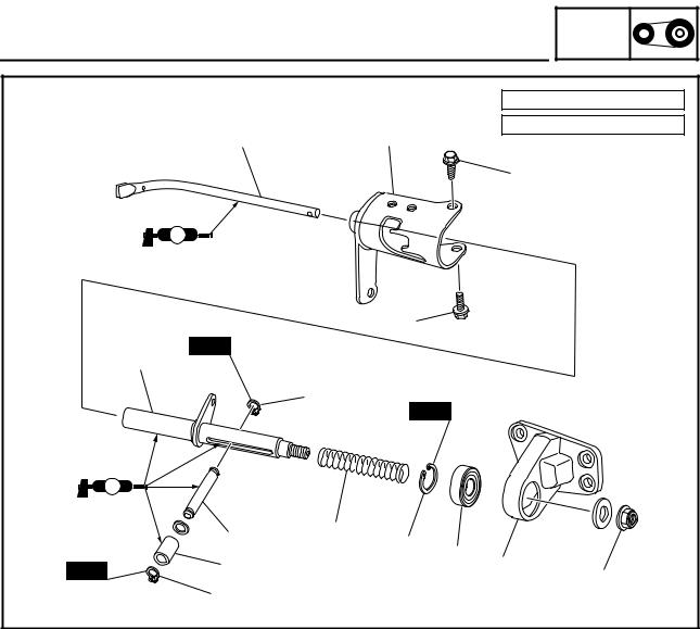
|
|
SHIFT LEVER |
POWR |
||
|
|
TR |
|||
|
|
|
|
È: 23 Nm (2.3 m • kg, 17 ft • lb) |
|
|
7 |
0 |
|
É: 59 Nm (5.9 m • kg, 43 ft • lb) |
|
|
|
|
|
||
|
|
|
|
È |
|
|
LS |
|
|
|
|
|
|
È |
|
|
|
|
New |
|
|
|
|
|
8 |
|
|
|
|
|
|
4 |
|
|
|
|
|
New |
|
|
|
|
LS |
|
|
|
|
|
6 |
9 |
|
|
|
|
2 |
|
|
|
|
|
|
3 |
|
|
|
New |
5 |
|
1 |
É |
|
|
|
|
|
||
|
|
|
|
|
|
|
4 |
|
|
|
|
Order |
Job name/Part name |
Q’ty |
Remarks |
|
|
|
|
|
Shift lever disassembly |
|
Remove the parts in the order listed below. |
1 |
Shift lever stay |
1 |
|
2 |
Circlip |
1 |
|
3 |
Bearing |
1 |
|
4 |
Circlip |
2 |
|
5 |
Collar |
1 |
|
6 |
Shift lever pin |
1 |
|
7 |
Shift lever |
1 |
|
8 |
Shift lever guide |
1 |
|
9 |
Spring |
1 |
|
0 |
Shift lever stopper |
1 |
|
|
|
|
For assembly, reverse the disassembly pro- |
|
|
|
cedure. |
|
|
|
|
20

|
|
SHIFT LEVER |
|
|
|
INSTALLATION |
|
|
1 |
1. Install: |
|
3 |
• Shift lever 1 |
||
|
|||
|
|
• Shift lever stopper 2 |
|
|
|
• Shift guide 3 |
|
2 |
|
• Shift lever pin 4 |
|
4 |
|
• Spring |
POWR
TR
6 4
4
1
2 5
5
 3
3
Installation steps:
•Install the shift lever 1 onto the shift lever stopper 2.
•Install the shift lever guide 3 and spring 5 onto the shift lever, position the shift lever and shift lever guide as shown, and then install the shift lever pin 4.
NOTE:
Make sure that the end of the spring 5 is installed between the washer 6 and the shift lever guide 3.
21
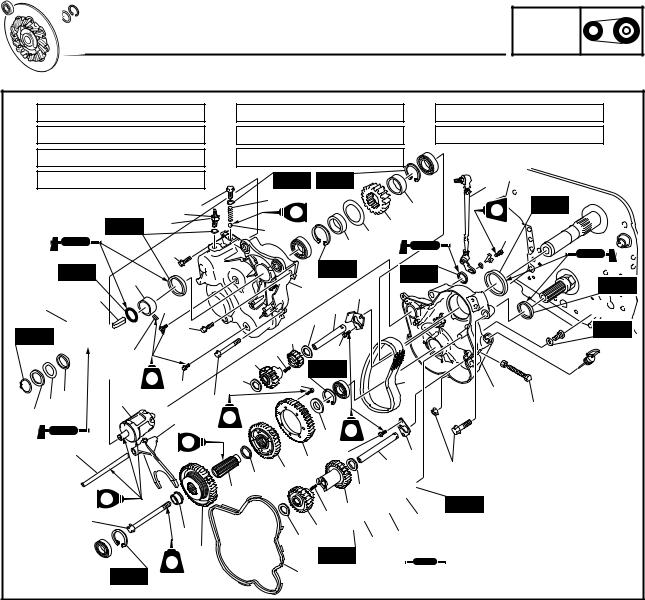
DRIVE CHAIN HOUSING
DRIVE CHAIN HOUSING
POWR
TR
È: 6 Nm (0.6 m • kg, 4.3 ft • lb) |
|
Ì: 18 Nm (1.8 m • kg, 13 ft • lb) |
Ï: 43 Nm (4.3 m • kg, 31 ft • lb) |
||||||||||
É: 10 Nm (1.0 m • kg, 7.2 ft • lb) |
|
Í: 20 Nm (2.0 m • kg, 14 ft • lb) |
Ð: |
55 Nm (5.5 m • kg, 40 ft • lb) |
|||||||||
Ê: 14 Nm (1.4 m • kg, 10 ft • lb) |
|
Î: |
24 Nm (2.4 m • kg, 17 ft • lb) |
|
|
|
|||||||
Ë: 16 Nm (1.6 m • kg, 11 ft • lb) |
|
|
|
New |
|
New |
|
7 |
|
||||
|
|
|
Í |
Ì |
|
|
9 |
|
|
37 |
LTLT |
New |
|
|
|
|
|
|
|
|
G |
|
|
||||
|
|
|
|
|
|
|
|
|
|
||||
|
|
New 11 |
|
|
|
|
10 |
|
32 |
|
Ê |
|
|
|
|
|
|
|
|
|
|
|
|
27 28 |
|
|
|
|
|
|
É |
|
|
|
|
|
|
|
|
|
|
|
New |
6 |
|
|
|
|
|
12 |
New |
New |
|
New |
|
|
|
|
|
|
|
|
38 |
|
|
||||
|
|
5 |
|
|
|
|
|
|
|
||||
4 |
|
|
|
|
|
|
|
|
|
|
|
||
|
|
É |
|
|
|
|
|
|
39 |
|
|
Ë |
|
|
|
|
Î |
|
|
|
|
30 |
|
|
New |
||
New |
|
|
|
|
|
29 |
|
|
|
|
|||
|
|
|
(3) |
|
|
|
|
|
|
||||
|
|
È |
|
|
19 |
|
É |
|
|
|
|||
|
|
|
|
(2) |
17 |
|
|
|
|
||||
|
|
|
|
|
New |
|
|
|
|||||
|
|
|
|
|
|
|
|
|
|||||
|
3 |
LT |
É |
|
|
16 |
Ì |
33 |
44 |
|
|||
|
13 |
|
|
Ï |
|
|
|
|
|
|
|||
2 |
|
|
|
|
|
|
|
|
8 |
||||
|
|
15 |
|
|
|
|
|
|
|
|
|||
1 |
|
|
|
LT |
|
|
|
|
|
|
|
||
14 |
G |
|
|
43 LT |
|
|
|
|
|
É |
|
41 40 |
|
|
|
|
31 |
|
||
|
|
23 |
34 |
|
|
|
|
22 |
|
36 |
|
||
G |
|
|
|
|||
|
|
|
19 35 |
|
|
|
Ð |
|
|
|
|
25 |
|
|
20 |
|
16 |
18 |
26 |
24 |
|
21 |
|
New |
|
||
|
|
|
|
|
||
|
LT |
|
42 |
|
|
|
|
New |
|
|
|
||
(2)
Ï
New
 : 1 ESSO beacon 325 grease or Aeroshell grease #7A
Order |
Job name/Part name |
Q’ty |
Remarks |
|
|
|
|
|
Drive chain housing removal |
|
Remove the parts in the order listed below. |
|
Right side cover/shift lever/parking brake/ |
|
Refer to “SHIFT LEVER” and “BRAKE”. |
|
brake caliper |
|
|
1 |
Shim |
— |
t = 0.5 |
2 |
Washer |
1 |
t = 1.0 |
3 |
Collar |
1 |
|
4 |
Brake disc |
1 |
|
5 |
Straight key |
1 |
|
6 |
Collar |
1 |
|
7 |
Shift rod |
1 |
|
8 |
Chain tension adjusting bolt |
1 |
Loosen. |
9 |
Spring |
1 |
|
10 |
Ball |
1 |
|
11 |
Gear position switch |
1 |
|
12 |
Drive chain housing cover |
1 |
|
13 |
Shift drum |
1 |
|
|
|
|
|
22

|
|
|
|
|
|
|
|
DRIVE CHAIN HOUSING |
POWR |
||||
|
|
|
|
|
|
|
|
TR |
|||||
È: 6 Nm (0.6 m • kg, 4.3 ft • lb) |
|
Ì: 18 Nm (1.8 m • kg, 13 ft • lb) |
Ï: 43 Nm (4.3 m • kg, 31 ft • lb) |
||||||||||
É: 10 Nm (1.0 m • kg, 7.2 ft • lb) |
|
Í: 20 Nm (2.0 m • kg, 14 ft • lb) |
Ð: |
55 Nm (5.5 m • kg, 40 ft • lb) |
|||||||||
Ê: 14 Nm (1.4 m • kg, 10 ft • lb) |
|
Î: |
24 Nm (2.4 m • kg, 17 ft • lb) |
|
|
|
|||||||
Ë: 16 Nm (1.6 m • kg, 11 ft • lb) |
|
|
|
New |
|
New |
|
7 |
|
||||
|
|
|
Í |
Ì |
|
|
9 |
|
|
37 |
LTLT |
New |
|
|
|
|
|
|
|
|
G |
|
|
||||
|
|
|
|
|
|
|
|
|
|
||||
|
|
New 11 |
|
|
|
|
10 |
|
32 |
|
Ê |
|
|
|
|
|
|
|
|
|
|
|
|
27 28 |
|
|
|
|
|
|
É |
|
|
|
|
|
|
|
|
|
|
|
New |
6 |
|
|
|
|
|
12 |
New |
New |
|
New |
|
|
|
|
|
|
|
|
38 |
|
|
||||
|
|
5 |
|
|
|
|
|
|
|
||||
4 |
|
|
|
|
|
|
|
|
|
|
|
||
|
|
É |
|
|
|
|
|
|
39 |
|
|
Ë |
|
|
|
|
Î |
|
|
|
|
30 |
|
|
New |
||
New |
|
|
|
|
|
29 |
|
|
|
|
|||
|
|
|
(3) |
|
|
|
|
|
|
||||
|
|
È |
|
|
19 |
|
É |
|
|
|
|||
|
|
|
|
(2) |
17 |
|
|
|
|
||||
|
|
|
|
|
New |
|
|
|
|||||
|
|
|
|
|
|
|
|
|
|||||
|
3 |
LT |
É |
|
|
16 |
Ì |
33 |
44 |
|
|||
|
13 |
|
|
Ï |
|
|
|
|
|
|
|||
2 |
|
|
|
|
|
|
|
|
8 |
||||
|
|
15 |
|
|
|
|
|
|
|
|
|||
1 |
|
|
|
LT |
|
|
|
|
|
|
|
||
14 |
G |
|
|
43 LT |
|
|
|
|
|
É |
|
41 40 |
|
|
|
|
31 |
|
||
|
|
23 |
34 |
|
|
|
|
22 |
|
36 |
|
||
G |
|
|
|
|||
|
|
|
19 35 |
|
|
|
Ð |
|
|
|
|
25 |
|
|
20 |
|
16 |
18 |
26 |
24 |
|
21 |
|
New |
|
||
|
|
|
|
|
||
|
LT |
|
42 |
|
|
|
|
New |
|
|
|
||
(2)
Ï
New
 : 1 ESSO beacon 325 grease or Aeroshell grease #7A
Order |
Job name/Part name |
Q’ty |
Remarks |
|
|
|
|
14 |
Shift fork guide bar |
1 |
|
15 |
Shift fork |
1 |
|
16 |
Washer |
2 |
|
17 |
Counter gear |
1 |
|
18 |
Low pinion gear |
1 |
|
19 |
Spring |
2 |
|
20 |
Collar |
1 |
|
21 |
Driven gear |
1 |
|
22 |
Journal |
1 |
|
23 |
Washer |
1 |
|
24 |
Chain tensioner |
1 |
|
25 |
Washer |
1 |
|
26 |
Collar |
1 |
|
27 |
Collar |
1 |
|
28 |
Washer |
1 |
|
29 |
Reverse drive gear |
1 |
|
|
|
|
|
23

|
|
|
|
|
|
|
|
DRIVE CHAIN HOUSING |
POWR |
||||
|
|
|
|
|
|
|
|
TR |
|||||
È: 6 Nm (0.6 m • kg, 4.3 ft • lb) |
|
Ì: 18 Nm (1.8 m • kg, 13 ft • lb) |
Ï: 43 Nm (4.3 m • kg, 31 ft • lb) |
||||||||||
É: 10 Nm (1.0 m • kg, 7.2 ft • lb) |
|
Í: 20 Nm (2.0 m • kg, 14 ft • lb) |
Ð: |
55 Nm (5.5 m • kg, 40 ft • lb) |
|||||||||
Ê: 14 Nm (1.4 m • kg, 10 ft • lb) |
|
Î: |
24 Nm (2.4 m • kg, 17 ft • lb) |
|
|
|
|||||||
Ë: 16 Nm (1.6 m • kg, 11 ft • lb) |
|
|
|
New |
|
New |
|
7 |
|
||||
|
|
|
Í |
Ì |
|
|
9 |
|
|
37 |
LTLT |
New |
|
|
|
|
|
|
|
|
G |
|
|
||||
|
|
|
|
|
|
|
|
|
|
||||
|
|
New 11 |
|
|
|
|
10 |
|
32 |
|
Ê |
|
|
|
|
|
|
|
|
|
|
|
|
27 28 |
|
|
|
|
|
|
É |
|
|
|
|
|
|
|
|
|
|
|
New |
6 |
|
|
|
|
|
12 |
New |
New |
|
New |
|
|
|
|
|
|
|
|
38 |
|
|
||||
|
|
5 |
|
|
|
|
|
|
|
||||
4 |
|
|
|
|
|
|
|
|
|
|
|
||
|
|
É |
|
|
|
|
|
|
39 |
|
|
Ë |
|
|
|
|
Î |
|
|
|
|
30 |
|
|
New |
||
New |
|
|
|
|
|
29 |
|
|
|
|
|||
|
|
|
(3) |
|
|
|
|
|
|
||||
|
|
È |
|
|
19 |
|
É |
|
|
|
|||
|
|
|
|
(2) |
17 |
|
|
|
|
||||
|
|
|
|
|
New |
|
|
|
|||||
|
|
|
|
|
|
|
|
|
|||||
|
3 |
LT |
É |
|
|
16 |
Ì |
33 |
44 |
|
|||
|
13 |
|
|
Ï |
|
|
|
|
|
|
|||
2 |
|
|
|
|
|
|
|
|
8 |
||||
|
|
15 |
|
|
|
|
|
|
|
|
|||
1 |
|
|
|
LT |
|
|
|
|
|
|
|
||
14 |
G |
|
|
43 LT |
|
|
|
|
|
É |
|
41 40 |
|
|
|
|
31 |
|
||
|
|
23 |
34 |
|
|
|
|
22 |
|
36 |
|
||
G |
|
|
|
|||
|
|
|
19 35 |
|
|
|
Ð |
|
|
|
|
25 |
|
|
20 |
|
16 |
18 |
26 |
24 |
|
21 |
|
New |
|
||
|
|
|
|
|
||
|
LT |
|
42 |
|
|
|
|
New |
|
|
|
||
(2)
Ï
New
 : 1 ESSO beacon 325 grease or Aeroshell grease #7A
Order |
Job name/Part name |
Q’ty |
Remarks |
|
|
|
|
30 |
Washer |
1 |
|
31 |
Low drive gear |
1 |
|
32 |
Drive sprocket |
1 |
|
33 |
Drive chain |
1 |
|
34 |
Driven sprocket |
1 |
|
35 |
Low wheel gear |
1 |
|
36 |
Washer |
1 |
|
37 |
Collar |
1 |
|
38 |
Plate |
1 |
|
39 |
Shaft |
1 |
|
40 |
Plate |
1 |
|
41 |
Shaft |
1 |
|
42 |
Rubber seal |
1 |
|
43 |
Washer |
1 |
|
44 |
Drive chain housing |
1 |
|
|
|
|
For installation, reverse the removal proce- |
|
|
|
dure. |
|
|
|
|
24
 Loading...