


WaveRunner
VX 700
 VX 700 (F2V)
SERVICE MANUAL
F2V-28197-ZN-11
Preface
This manual has been prepared by Yamaha primarily for use by Yamaha dealers and their trained mechanics when performing maintenance procedures and repairs to Yamaha equipment. It has been written to suit the needs of persons who have a basic understanding of the mechanical and electrical concepts and procedures inherent in the work, for without such knowledge attempted repairs or service to the equipment could render it unsafe or unfit for use.
Because Yamaha has a policy of continuously improving its products, models may differ in detail from the descriptions and illustrations given in this publication. Use only the latest edition of this manual. Authorized Yamaha dealers are notified periodically of modifications and significant changes in specifications and procedures, and these are incorporated in successive editions of this manual. Also, up-to-date parts information is available on YPEC-web. Additional information and up-to-date information on Yamaha products and services are available on Yamaha Service Portal.
Important information
Particularly important information is distinguished in this manual by the following notations:
 The Safety Alert Symbol means ATTENTION! BECOME ALERT! YOUR SAFETY IS INVOLVED!
A WARNING indicates a hazardous situation which, if not avoided, could result in death or serious injury.
A NOTICE indicates special precautions that must be taken to avoid damages to the watercraft or other property.
TIP:
A TIP provides key information to make procedures easier or clearer.
WaveRunner
VX 700
SERVICE MANUAL ©2010 by Yamaha Motor Co., Ltd.
1st Edition, September 2010 All rights reserved.
Any reprinting or unauthorized use without the written permission of Yamaha Motor Co., Ltd.
is expressly prohibited.
Contents
General information
Specification
Maintenance
Fuel system
Power unit
Jet pump unit
Electrical system
Hull and hood
Troubleshooting
GEN INFO
SPEC
MNT
FUEL
POWR
JET
PUMP
–+
ELEC
HULL HOOD
TRBL SHTG
1
2
3
4
5
6
7
8
9
Appendix
A
GEN
INFO
General information
.....................................................Safety while working |
1-1 |
1 |
|
Rotating part |
1-1 |
||
|
|||
Hot part....................................................................................... |
1-1 |
|
|
Electric shock ............................................................................. |
1-1 |
|
|
.......................................................................................Impeller |
1-1 |
|
|
Handling of gasoline................................................................... |
1-1 |
|
|
Ventilation................................................................................... |
1-2 |
|
|
Self-protection ............................................................................ |
1-2 |
|
|
Working with crane..................................................................... |
1-2 |
|
|
Handling of heat gun .................................................................. |
1-3 |
|
|
Part, lubricant, and sealant......................................................... |
1-3 |
|
|
Handling of sealant..................................................................... |
1-3 |
|
|
Special service tool .................................................................... |
1-3 |
|
|
Tightening torque ....................................................................... |
1-3 |
|
|
Non-reusable part....................................................................... |
1-3 |
|
|
Disassembly and assembly........................................................ |
1-4 |
|
|
How to use this manual ..................................................... |
1-5 |
|
|
Manual format ............................................................................ |
1-5 |
|
|
Abbreviation ............................................................................... |
1-6 |
|
|
Adhesive, lubricant, sealant, |
|
|
|
and thread locking agent................................................... |
1-7 |
|
|
Symbol ....................................................................................... |
1-7 |
|
|
Special service tool............................................................ |
1-8 |
|
|
Model feature .................................................................... |
1-10 |
|
|
Identification number ................................................................ |
1-10 |
|
GEN INFO
General information
 Safety while working
To prevent an accident or injury and to provide quality service, observe the following safety procedures.
Rotating part
•Hands, feet, hair, jewelry, clothing, personal flotation device straps, and so on, can become entangled with internal rotating parts of the engine or jet pump unit, resulting in serious injury or death.
•Keep hands, feet, hair, jewelry, clothing, personal flotation device straps, and so on, away from any exposed moving parts when operating the engine with the seat removed.
•Keep away from intake grate while engine is on. Items such as hair, clothing, or personal flotation device straps can become entangled in moving parts resulting in severe injury.
Hot part
During and after operation, engine parts are hot enough to cause burns. Do not touch any parts in the engine compartment until the engine has cooled.
Electric shock
Do not touch any electrical parts while starting or operating the engine. Otherwise, shock or electrocution could result.
Handling of gasoline
•Gasoline is highly flammable. Keep gasoline and all flammable products away from heat, sparks, and open flames.
•Gasoline is poisonous and can cause injury or death. Handle gasoline with care. Never siphon gasoline by mouth. If you swallow some gasoline, inhale a lot of gasoline vapor, or get some gasoline in your eyes, see your doctor immediately. If gasoline spills on your skin, wash with soap and water. If gasoline spills on your clothing, change your clothes.
Impeller
Do not hold the impeller with your hands when loosening or tightening the impeller.
1-1
 Safety while working
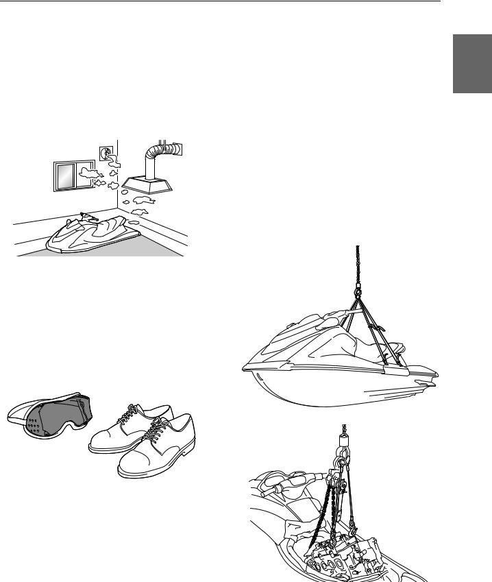
Ventilation
•Gasoline vapor and exhaust gas are heavier than air and extremely poisonous. If gasoline vapor or exhaust gas is inhaled in large quantities, it may cause loss of consciousness and death within a short time.
•When test running an engine indoors (for example, in a water tank) make sure to do so where adequate ventilation can be maintained.
Working with crane
• When moving the watercraft, or when lifting |
|
the engine during removal or installation, |
1 |
make sure to use a crane with a lifting |
|
capacity that is equal to or more than the |
|
weight of the watercraft or engine respec- |
tively.
•When lifting the watercraft, use the watercraft lift harness and make sure that the watercraft is in a stable position when moving it.
•Use the wire ropes of adequate strength, and lift up the engine unit using the three point suspension. If the engine unit does not have three or more points to be suspended, support it using additional ropes or the like so that the engine unit can be lifted and carried in a stable manner.
Self-protection
•Protect your eyes by wearing safety glasses or safety goggles during all operations involving drilling and grinding, or when using an air compressor.
•Protect your hands and feet by wearing protective gloves and safety shoes when necessary.
1-2
GEN INFO
General information
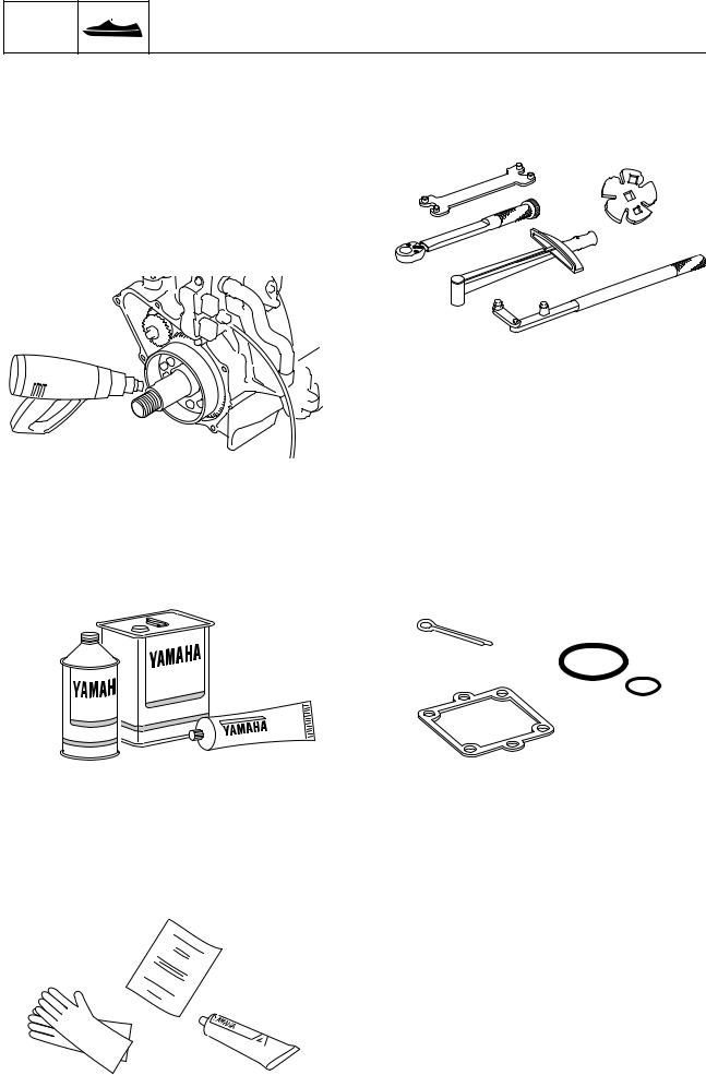
Handling of heat gun
•Improper handling of a heat gun may result in burns. For information on the proper handling of the heat gun, see the operation manual issued by the manufacturer.
•When using a heat gun, keep it away from the gasoline and oil, to prevent a fire.
•Components become hot enough to cause burns. Do not touch any hot components directly.
Special service tool
Use the recommended special service tools to work safely, and to protect parts from damage.
Part, lubricant, and sealant
Use only genuine Yamaha parts, lubricants, and sealants, or those recommended by Yamaha, when servicing or repairing the watercraft.
Handling of sealant
•Wear protective gloves to protect your skin, when using the sealants.
•See the material safety data sheet issued by the manufacturer. Some of the sealants may be harmful to human health.
Tightening torque
Follow the tightening torque specifications provided throughout the manual. When tightening nuts, bolts, and screws, tighten the large sizes first, and tighten fasteners starting in the center and moving outward.
Non-reusable part
Always use new gaskets, seals, O-rings, cotter pins, and so on, when installing or assembling parts.
1-3
 Safety while working
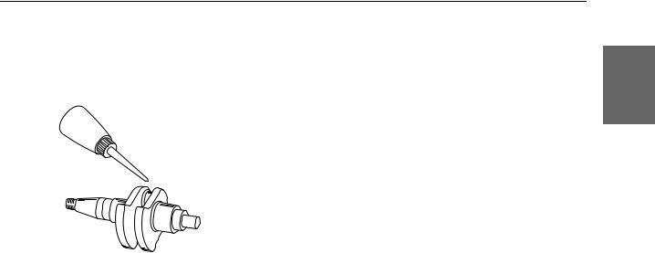
Disassembly and assembly
• Use compressed air to remove dust and dirt during disassembly.
• Apply engine oil to the contact surfaces of 1 moving parts before assembly.
•Install bearings so that the bearing identification mark is facing in the direction indicated in the installation procedure. In addition, make sure to lubricate the bearings liberally.
•Apply a thin coat of water resistant grease to the lip and periphery of an oil seal before installation.
•Check that moving parts operate normally after assembly.
1-4
GEN INFO
General information
How to use this manual
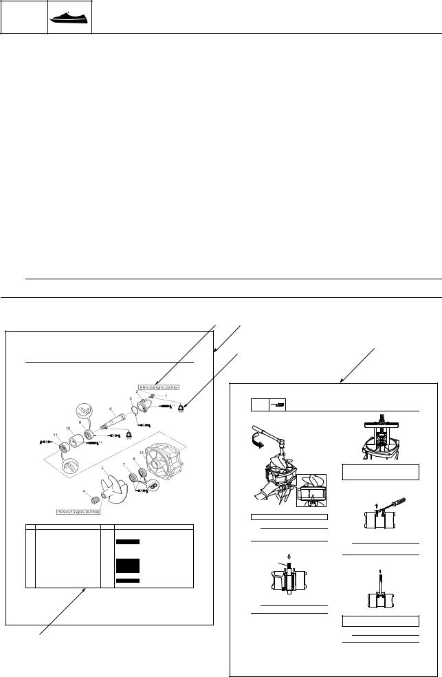
Manual format
The format of this manual has been designed to make service procedures clear and easy to understand. Use the information below as a guide for effective and quality service.
•Parts are shown and detailed in an exploded diagram and are listed in the component list (see 1 in the following figure for an example page).
•The component list consists of part names and quantities, as well as bolt and screw dimensions (see 2 in the following figure). To assemble or install the components, reverse the steps indicated in the component list.
•Symbols are used to indicate important aspects of a procedure, such as the grade of lubricant and the lubrication point (see 3 in the following figure).
•Tightening torque specifications are provided in the exploded diagrams (see 4 in the following figure), and in the related detailed instructions. Some torque specifications are listed in stages as torque figures or angles in degrees.
•Separate procedures and illustrations are used to explain the details of removal, checking, and installation where necessary (see 5 in the following figure for an example page).
TIP:
For troubleshooting procedures, see Chapter 9, “Troubleshooting.”
|
|
|
|
4 |
1 |
|
|
|
|
|
|
|
|
|
3 |
|
|
|
5 |
|
|
|
|
|
|
|
|
|
|
|
Jet thrust nozzle, impeller duct, and impeller housing / Impeller duct and drive shaft |
|
|
|
|
|
|||
Impeller duct and drive shaft |
|
|
|
|
|
|
|
|
|
|
|
|
|
|
|
JET |
|
|
|
|
|
|
|
|
PUMP |
Jet pump unit |
|
|
|
|
|
|
|
|
Drive shaft removal |
|
|
||
|
|
|
|
|
1. |
Remove the impeller. |
|
|
|
|
|
|
|
|
|
|
|
Stopper guide plate: 90890-06501 |
|
|
|
|
|
|
|
|
|
Bearing puller assembly: 90890-06535 |
|
|
|
|
|
|
|
|
|
Stopper guide stand: 90890-06538 |
|
|
|
|
|
|
|
|
|
4. Remove the oil seals. |
|
|
|
|
|
|
|
|
a |
|
|
|
|
|
|
|
|
a |
|
|
|
|
|
|
|
|
Crankshaft holder 20: 90890-06552 |
|
|
||
No. |
Part name |
Q’ty |
|
Remarks |
TIP: |
|
|
|
|
1 |
Bolt |
3 |
M6 |
20 mm |
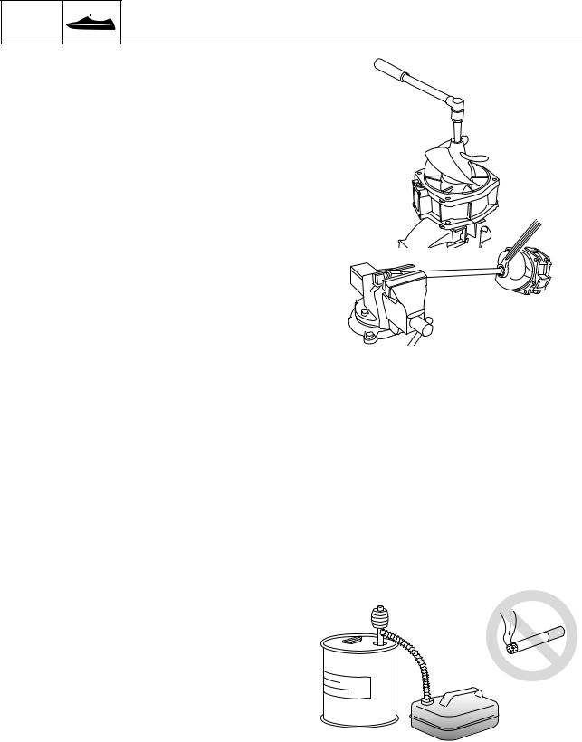
Hold the impeller duct assy. in a vise |
|
|
||
2 |
Cap |
1 |
|
|
between two aluminum plates a. |
TIP: |
|||
3 |
O-ring |
1 |
Not reusable |
|
|
|
|||
4 |
Cap |
1 |
|
|
2. Remove the drive shaft 1. |
Remove the oil seals using a flat head screw- |
|||
5 |
Impeller |
1 |
|
|
driver. |
||||
|
|
|
|
|
|||||
6 |
Drive shaft |
1 |
|
|
|
|
|
|
|
7 |
Oil seal |
1 |
Not reusable |
|
1 |
|
5. |
Remove the front bearing. |
|
8 |
Oil seal |
1 |
Not reusable |
|
|
|
|
|
|
9 |
Rear bearing |
1 |
Not reusable |
|
|
|
|
|
|
10 |
Spacer |
1 |
|
|
|
|
|
|
|
11 |
Front bearing |
1 |
Not reusable |
|
|
|
|
|
|
12 |
Impeller duct |
1 |
|
|
|
|
|
|
|
*: EPNOC grease AP #0 |
|
|
|
|
|
|
|
|
|
|
|
|
|
|
TIP: |
|
|
|
|
|
|
|
|
|
Remove the drive shaft using a press. |
|
|
||
|
|
|
|
6-6 |
|
|
|
|
|
|
|
|
|
|
3. Remove the rear bearing. |
Driver rod L3: 90890-06652 |
|||
|
|
|
|
|
Needle bearing attachment: 90890-06614 |
||||
|
|
|
|
|
|
|
|
||
2 |
|
|
|
|
|
|
TIP: |
||
|
|
|
|
|
|
Remove the front bearing using a press. |
|||
|
|
|
|
|
|
|
|
Impeller check |
|
|
|
|
|
|
|
|
|
1. Check the impeller. Replace if damaged. |
|
|
|
|
|
|
6-7 |
|
|
|
|
1-5 |
|
|
|
|
|
|
|
|
|
How to use this manual
Abbreviation
The following abbreviations are used in this service manual.
|
|
|
1 |
Abbreviation |
Description |
|
|
|
|
|
|
BOW |
Bow end |
|
|
|
|
|
|
CDI |
Capacitor discharge ignition |
|
|
EX |
Exhaust |
|
|
|
|||
|
|
|
|
IN |
Intake |
|
|
|
|
|
|
NMMA |
National Marine Manufacturers Association |
|
|
|
|
|
|
PON |
Pump Octane Number |
|
|
|
|
|
|
PORT |
Port side |
|
|
|
|
|
|
RON |
Research Octane Number |
|
|
|
|
|
|
STBD |
Starboard side |
|
|
|
|
|
|
STERN |
Stern end |
|
|
|
|
|
|
TDC |
Top Dead Center |
|
|
|
|
|
|
1-6
GEN INFO
General information
Adhesive, lubricant, sealant, and thread locking agent
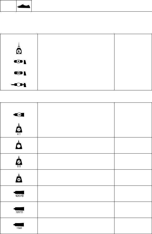
Symbol
Symbols in an exploded diagram or illustration indicate the grade of lubricant and the lubrication points.
|
Symbol |
Name |
Application |
||
|
|
|
|
Yamaha 2-stroke motor oil |
Lubricant |
|
|
|
|
|
|
|
|
|
|
|
|
|
|
|
|
Water resistant grease |
Lubricant |
|
|
|
|
(Yamaha grease A) |
|
|
|
|
|
|
|
|
|
|
|
|
|
|
|
|
|
|
|
|
|
|
|
Molybdenum disulfide grease |
Lubricant |
|
|
|
|
|
|
|
|
|
|
|
|
|
|
|
|
|
|
|
|
|
|
Epnoc grease AP#0 |
Lubricant |
EP
Symbols in an exploded diagram or illustration indicate the type of adhesive, sealant, or thread locking agent and the application points.
Symbol |
Name |
Application |
Gasket Maker |
|
Sealant |
|
|
|
LOCTITE 271 (red) |
|
Thread locking agent |
LOCTITE 242 (blue) |
Thread locking agent |
LT
242
LOCTITE 572 (white) |
Sealant |
Silicone sealant |
Sealant |
ThreeBond 1207B |
Sealant |
ThreeBond 1207D |
Sealant |
ThreeBond 1322 |
Thread locking agent |
1-7
Adhesive, lubricant, sealant, and thread locking agent / Special service tool
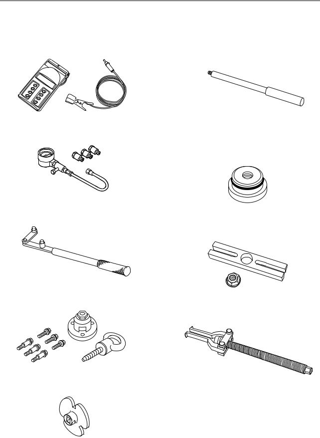
Special service tool
Special service tools with Yamaha part numbers (90890-*****) are distributed by the Parts Division.
Digital tachometer |
Driver rod L3 |
1 |
|
||
90890-06760 |
90890-06652 |
|
|
|
|
Compression gauge |
Needle bearing attachment |
90890-03160 |
90890-06614 |
|
Ball bearing attachment |
|
90890-06634 |
Flywheel holder 90890-06522
Stopper guide plate 90890-06501
Flywheel puller 90890-06521
Bearing puller assembly 90890-06535
Coupler wrench 90890-06425
1-8
GEN INFO
General information
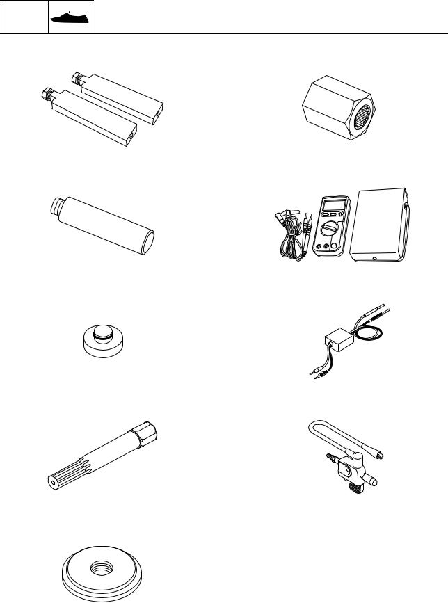
Stopper guide stand |
Drive shaft holder 5 |
90890-06538 |
90890-06519 |
Driver rod LS |
Digital circuit tester |
90890-06606 |
90890-03174 |
Ball bearing attachment |
Peak voltage adapter B |
90890-06631 |
90890-03172 |
Crankshaft holder 20 |
Ignition tester (Spark gap tester) |
90890-06552 |
90890-06754 |
Bearing outer race attachment 90890-06628
1-9

Special service tool / Model feature
Model feature
Identification number
Primary I.D. number
The primary I.D. number is stamped on a label attached to the inside of the engine compartment.
Starting engine serial number: 6CP: 1000001
Jet pump unit serial number |
1 |
The jet pump unit serial number is stamped |
|
on a label attached to the intermediate hous- |
ing.
1 |
2 |
3 |
|
|
PRI-I.D. |
MODEL |
|
F2V |
YAMAHA MOTOR CO., LTD.
ASSEMBLED IN U.S.A. FROM AMERICAN AND JAPANESE
COMPONENTS.
ASSEMBLÉ AUX ÉTATS-UNIS DE PIÈCES AMÉRICAINES ET
JAPONAISES.
1 Model name
2 Hull type
3 Primary I.D. number
Starting primary I.D. number:
F2V: 800101
Engine serial number
The engine serial number is stamped on a label attached to the engine unit.
1
2
3
1 Engine name
2 Engine type
3 Engine serial number
2 1 3
1 Jet pump unit name
2 Jet pump unit type
3 Jet pump unit serial number
Hull identification number (H.I.N.)
The H.I.N. is stamped on a plate attached to the boarding platform.
1-10

GEN INFO
General information
— MEMO —
1-11

SPEC
Specification |
|
|
|
Model data .......................................................................... |
2-1 |
|
|
Model code................................................................................. |
2-1 |
|
|
Dimension and weight ................................................................ |
2-1 |
|
|
Performance............................................................................... |
2-1 |
|
|
Power unit .................................................................................. |
2-1 |
|
|
2 |
|||
Drive unit .................................................................................... |
2-2 |
||
Fuel and oil requirement |
2-2 |
||
|
|||
Battery requirement.................................................................... |
2-2 |
|
|
Fuel system technical data |
2-3 |
|
|
|
|||
Fuel system ................................................................................ |
2-3 |
|
|
Power unit technical data .................................................. |
2-3 |
|
|
Power unit .................................................................................. |
2-3 |
|
|
Cylinder head assy..................................................................... |
2-3 |
|
|
Crank case assy......................................................................... |
2-4 |
|
|
Jet pump unit technical data............................................. |
2-5 |
|
|
Jet pump unit.............................................................................. |
2-5 |
|
|
Electrical technical data .................................................... |
2-5 |
|
|
Ignition system ........................................................................... |
2-5 |
|
|
Charging system ........................................................................ |
2-6 |
|
|
Control system ........................................................................... |
2-6 |
|
|
Starting system........................................................................... |
2-7 |
|
|
Meter system.............................................................................. |
2-7 |
|
|
Specified tightening torque............................................... |
2-8 |
|
|
Fuel system ................................................................................ |
2-8 |
|
|
Power unit .................................................................................. |
2-8 |
|
|
Jet pump unit............................................................................ |
2-10 |
|
|
Electrical system ...................................................................... |
2-10 |
|
|
Hull and hood ........................................................................... |
2-11 |
|
|
General tightening torque ............................................... |
2-12 |
|
|
Cooling system ................................................................ |
2-13 |
|
|
Cable and hose routing ................................................... |
2-14 |
|
Starboard bow view.................................................................. |
2-14 |
Top view ................................................................................... |
2-15 |
Port view................................................................................... |
2-17 |

SPEC
Specification
Model data
Model code
Item |
Unit |
Model |
|
VX 700 |
|||
|
|
||
Hull |
|
F2V |
|
Engine/jet |
|
6CP/6CP |
|
|
|
|
Dimension and weight
Item |
Unit |
Model |
|
VX 700 |
|||
|
|
||
Length |
mm (in) |
3220 (126.8) |
|
Width |
mm (in) |
1170 (46.1) |
|
Height |
mm (in) |
1160 (45.7) |
|
Dry weight |
kg (lb) |
283 (624) |
|
Maximum capacity |
Person/ |
3/240 (530) |
|
kg (lb) |
|||
|
|
||
|
|
|
Performance
Item |
Unit |
Model |
|
VX 700 |
|||
|
|
||
Full throttle operating range |
r/min |
7200 |
|
Trolling speed |
r/min |
1250–1350 |
|
Maximum fuel consumption |
L/h (US gal/ |
34.0 (9.0, 7.5) |
|
h, lmp.gal/h) |
|||
|
|
||
Cruising range |
h |
1.47 |
|
|
|
|
Power unit
Item |
Unit |
Model |
|
VX 700 |
|||
|
|
||
Type |
|
2-stroke L2 |
|
Cylinder quantity |
cm3 (cu. in) |
2 |
|
Total displacement |
701 (42.8) |
||
Bore × stroke |
mm (in) |
81.0 × 68.0 (3.19 × 2.68) |
|
Compression ratio |
|
7.2 : 1 |
|
Intake system |
|
Reed valve |
|
Starting enrichment |
|
Choke valve |
|
Scavenging system |
|
Loop charge |
|
Exhaust system |
|
Wet exhaust |
|
Lubrication system |
|
Oil injection |
|
Cooling system |
|
Water cooled |
|
Starting system |
|
Electric starter |
|
Ignition system |
|
CDI |
|
Maximum ignition timing |
Degree |
BTDC 21° |
|
advance |
|||
|
|
||
Spark plug |
|
BR8HS (NGK) |
|
Spark plug gap |
mm (in) |
0.6–0.7 (0.024–0.038) |
|
Firing order |
|
1–2 |
|
|
|
|
2-1

Model data
Drive unit
Item |
Unit |
Model |
|
|
VX 700 |
|
|
||
|
|
|
|
|
Jet pump type |
|
Axial flow, single stage |
|
|
Impeller rotation |
|
Counterclockwise (viewed from rear) |
|
|
Transmission |
|
Constant mesh 1-speed |
|
|
Jet thrust nozzle horizontal |
Degree |
24 + 24 |
|
|
angle |
|
2 |
||
|
|
|
||
Trim system |
|
— |
|
|
|
|
|
||
Jet thrust nozzle trim angle |
Degree |
3 |
|
|
Fuel and oil requirement |
|
|
|
|
|
|
|
|
|
|
|
|
|
|
Item |
Unit |
Model |
|
|
VX 700 |
|
|
||
|
|
|
|
|
Fuel type |
|
Regular unleaded gasoline |
|
|
Fuel minimum rating |
PON |
86 |
|
|
|
RON |
90 |
|
|
Fuel tank capacity |
|
|
|
|
Total |
L (US gal, |
50 (13.2, 11.0) |
|
|
Imp.gal) |
|
|
||
|
|
|
|
|
Reserve |
L (US gal, |
12 (3.2, 2.6) |
|
|
Imp.gal) |
|
|
||
|
|
|
|
|
Engine oil type |
|
YAMALUBE 2-W |
|
|
Fuel and oil mixing ratio |
|
|
|
|
(Wide open throttle) |
|
50:1 |
|
|
Engine oil grade |
NMMA- |
TC-W3 |
|
|
|
certified |
|
|
|
Oil tank capacity |
L (US gal, |
3.8 (1.0, 0.8) |
|
|
Imp.gal) |
|
|
||
|
|
|
|
|
Battery requirement |
|
|
|
|
|
|
|
|
|
Item |
Unit |
Model |
|
|
VX 700 |
|
|
||
|
|
|
|
|
Type |
|
Fluid |
|
|
Capacity |
V/Ah |
12/19 |
|
|
Specific gravity at 20 °C (68 °F) |
|
1.265 |
|
|
2-2

SPEC
Specification
Fuel system technical data
Fuel system
Item |
Unit |
Model |
|
VX 700 |
|||
|
|
||
Carburetor |
|
|
|
Manufacturer |
|
Mikuni |
|
Model × quantity |
|
BN38 × 2 |
|
Type |
|
Floatless |
|
ID mark |
|
62T03F/03R |
|
Main jet (MJ) |
|
120 (front), 130 (rear) |
|
Main nozzle (MN) |
mm (in) |
2.5 (0.10) |
|
Pilot jet (PJ) |
|
67.5 |
|
Low speed screw |
turns out |
5/8 ± 1/4 |
|
Throttle valve |
|
190 |
|
Valve seat size |
mm (in) |
1.5 (0.06) |
|
Arm height |
mm (in) |
0–0.2 (0–0.008) |
|
High speed screw |
turns out |
5/8 ± 1/4 (front), 1 1/8 ± 1/4 (rear) |
|
Throttle lever free play |
mm (in) |
4.0–7.0 (0.16–0.28) |
|
|
|
|
Power unit technical data
Power unit
Item |
Unit |
Model |
|
VX 700 |
|||
|
|
||
Cylinder |
|
|
|
Minimum compression |
kPa (kgf/ |
590 (5.9, 84) |
|
pressure (*1) |
cm2, psi) |
||
|
(*1) Measuring conditions:
Ambient temperature 20 °C (68 °F), with spark plugs removed from all cylinders. The figures are for reference only.
Cylinder head assy.
Item |
Unit |
Model |
|
VX 700 |
|||
|
|
||
Cylinder head |
|
|
|
Warpage limit |
mm (in) |
0.1 (0.004) |
|
|
|
|
2-3
|
Fuel system technical data / Power unit technical data |
|
|||
Crank case assy. |
|
|
|
|
|
|
|
|
|
|
|
Item |
Unit |
Model |
|
|
|
VX 700 |
|
|
|||
|
|
|
|
||
Cylinder |
|
|
|
|
|
Bore |
mm (in) |
81.000–81.020 (3.1890–3.1898) |
|
|
|
Bore wear limit |
mm (in) |
81.100 (3.1929) |
|
|
|
Taper limit |
mm (in) |
0.080 (0.0031) |
|
|
|
Out-of-round limit |
mm (in) |
0.050 (0.0020) |
|
2 |
|
|
|
|
|
|
|
Piston |
|
|
|
|
|
Diameter |
mm (in) |
80.922–80.941 (3.1859–3.1866) |
|
||
Measuring point |
mm (in) |
10.0 (0.39) |
|
||
Ring groove (Top) |
mm (in) |
1.210–1.240 |
(0.0476–0.0488) |
|
|
|
|||||
Ring groove (2nd) |
mm (in) |
1.210–1.240 |
(0.0476–0.0488) |
|
|
Pin boss bore diameter |
mm (in) |
20.008–20.020 (0.7877–0.7882) |
|
|
|
Pin outside diameter |
mm (in) |
19.995–20.000 (0.7872–0.7874) |
|
|
|
Piston-to-cylinder clearance |
mm (in) |
0.080–0.085 |
(0.0031–0.0033) |
|
|
|
|
|
|
|
|
Piston ring |
|
|
|
|
|
End gap measuring point |
mm (in) |
10.0 (0.39) |
|
|
|
Top ring |
|
|
|
|
|
Type |
|
Keystone |
|
|
|
Dimension height (B) |
mm (in) |
1.170–1.190 |
(0.0461–0.0469) |
|
|
Dimension width (T) |
mm (in) |
2.750–2.950 |
(0.1083–0.1161) |
|
|
End gap (*1) |
mm (in) |
0.20–0.40 |
(0.008–0.015) |
|
|
Side clearance |
mm (in) |
0.03–0.05 |
(0.001–0.002) |
|
|
2nd ring |
|
|
|
|
|
Type |
|
Keystone |
|
|
|
Dimension height (B) |
mm (in) |
1.170–1.190 |
(0.0461–0.0469) |
|
|
Dimension width (T) |
mm (in) |
2.750–2.950 |
(0.1083–0.1161) |
|
|
End gap (*1) |
mm (in) |
0.20–0.40 |
(0.008–0.015) |
|
|
Side clearance |
mm (in) |
0.03–0.05 |
(0.001–0.002) |
|
|
|
|
|
|
|
|
Connecting rod |
|
|
|
|
|
Small end inside diameter |
mm (in) |
24.995–25.008 (0.9841–0.9846) |
|
|
|
Maximum small end axial |
mm (in) |
2.000 (0.0787) |
|
|
|
play |
|
|
|||
|
|
|
|
|
|
|
|
|
|
|
|
Crankshaft |
|
|
|
|
|
Width |
mm (in) |
61.950–62.000 (2.4390–2.4409) |
|
|
|
Deflection limit |
mm (in) |
0.050 (0.0020) |
|
|
|
Big end side clearance |
mm (in) |
0.250–0.750 |
(0.0098–0.0295) |
|
|
|
|
|
|
|
|
Reed valve |
|
|
|
|
|
Thickness |
mm (in) |
0.2 (0.01) |
|
|
|
Stopper height |
mm (in) |
8.8–9.2 |
(0.35–0.36) |
|
|
Warpage limit |
mm (in) |
0.2 (0.01) |
|
|
|
|
|
|
|
|
|
(*1) The figures are for reference only.
2-4

SPEC
Specification
Jet pump unit technical data
Jet pump unit
Item |
Unit |
Model |
|
VX 700 |
|||
|
|
||
Impeller housing |
|
|
|
Inside diameter |
mm (in) |
155.35–155.45 (6.116–6.120) |
|
Impeller-to-housing |
mm (in) |
0.35–0.45 (0.014–0.018) |
|
clearance |
|||
|
|
||
Clearance limit |
mm (in) |
0.60 (0.024) |
|
|
|
|
|
Impeller |
|
|
|
Material |
|
Stainless steel |
|
Blades number |
|
3 |
|
Pitch angle |
Degree |
13.2 |
|
|
|
|
|
Drive shaft |
|
|
|
Runout limit |
mm (in) |
0.01 (0.0004) |
|
|
|
|
|
Intermediate drive shaft |
|
|
|
Runout limit |
mm (in) |
0.30 (0.012) |
|
|
|
|
|
Nozzle |
|
|
|
Diameter |
mm (in) |
86.80–87.40 (3.417–3.441) |
|
maximum difference of jet |
mm (in) |
5 (0.2) |
|
thrust nozzle distances |
|||
|
|
||
|
|
|
Electrical technical data
Ignition system
Item |
Unit |
Model |
|
VX 700 |
|||
|
|
||
CDI unit |
|
|
|
Output peak voltage |
|
|
|
at cranking (loaded) |
V |
10 |
|
at 1500 r/min (loaded) |
V |
200 |
|
at 3500 r/min (loaded) |
V |
130 |
|
|
|
|
|
Pickup coil |
|
|
|
Output peak voltage |
|
|
|
at cranking (unloaded) |
V |
5.2 |
|
at cranking (loaded) |
V |
5.1 |
|
at 1500 r/min (loaded) |
V |
14.1 |
|
at 3500 r/min (loaded) |
V |
29.3 |
|
Resistance (*1) |
|
|
|
at 20 °C (68 °F) |
Ω |
12.6–15.4 |
(*1) The figures are for reference only.
2-5
|
Jet pump unit technical data / Electrical technical data |
|
||
Charging system |
|
|
|
|
|
|
|
|
|
Item |
Unit |
Model |
|
|
VX 700 |
|
|
||
|
|
|
|
|
Charge coil |
|
|
|
|
Output peak voltage |
|
|
|
|
at cranking (unloaded) |
V |
180 |
|
|
at cranking (loaded) |
V |
20 |
|
|
at 1500 r/min (loaded) |
V |
210 |
|
2 |
at 3500 r/min (loaded) |
V |
150 |
|
|
Resistance (*1) |
|
|
|
|
at 20 °C (68 °F) |
Ω |
497.7–608.3 |
|
|
Lighting coil |
|
|
|
|
|
|
|
|
|
Output peak voltage |
|
|
|
|
at cranking (unloaded) |
V |
8.7 |
|
|
at 1500 r/min (unloaded) |
V |
25.6 |
|
|
at 3500 r/min (unloaded) |
V |
47.3 |
|
|
Resistance (*1) |
|
|
|
|
at 20 °C (68 °F) |
Ω |
1.143–1.397 |
|
|
Minimum charging |
A at r/min |
14 at 6000 |
|
|
current |
|
|
||
|
|
|
|
|
|
|
|
|
|
Rectifier regulator |
|
|
|
|
Output peak voltage |
|
|
|
|
at 3500 r/min (loaded) |
V |
13.0 |
|
|
|
|
|
|
|
(*1) The figures are for reference only.
Control system
Item |
Unit |
Model |
|
VX 700 |
|||
|
|
||
Ignition coil |
|
|
|
Primary coil resistance |
|
|
|
at 20 °C (68 °F) |
Ω |
0.078–0.106 |
|
Secondary coil resistance |
|
|
|
at 20 °C (68 °F) |
kΩ |
14.336–30.464 |
|
Thermoswitch (engine) |
|
|
|
Input voltage (*1) |
V |
11.0–12.0 |
|
Continuity temperature |
°C (°F) |
77–83 (171–181) |
|
No continuity temperature |
°C (°F) |
63–77 (145–171) |
|
|
|
|
(*1) The figures are for reference only.
2-6

SPEC
Specification
Starting system
Item |
Unit |
Model |
|
VX 700 |
|||
|
|
||
Fuse |
|
|
|
Rating |
|
|
|
Main |
V/A |
12/10 |
|
|
|
|
|
Starter motor |
|
|
|
Type |
|
Constant mesh |
|
Output |
kW |
0.8 |
|
Cranking time limit |
Seconds |
30 |
|
Commutator diameter |
mm (in) |
27.0–28.0 (1.06–1.10) |
|
Commutator undercut (*1) |
mm (in) |
0.2–0.7 (0.008–0.028) |
|
Brush length |
mm (in) |
6.5–12.5 (0.26–0.49) |
(*1) The figures are for reference only.
Meter system
Item |
Unit |
Model |
|
VX 700 |
|||
|
|
||
Fuel level sensor |
|
|
|
Resistance |
|
|
|
at 20 °C (68 °F) |
|
|
|
Empty position |
Ω |
757.0–803.0 |
|
Full position |
Ω |
0–8.0 |
|
Oil level sensor |
|
|
|
Float distance (for continuity) |
mm |
37.0–41.0 (1.46–1.61) |
|
|
|
|
2-7

Electrical technical data / Specified tightening torque
Specified tightening torque
Fuel system
Part to tightened |
|
Screw |
|
Tightening torque |
|
See |
|
|
|
||
|
size |
N·m |
|
kgf·m |
|
ft·lb |
page |
|
|
|
|
|
|
|
|
|
|
|
|||||
Fuel cock knob screw |
|
ø4 |
2 |
|
0.2 |
|
1.5 |
4-1 |
|
|
|
Fuel cock assy./washer nut |
|
— |
5 |
|
0.5 |
|
3.7 |
4-1 |
|
|
|
Choke knob screw |
|
ø3 |
2 |
|
0.2 |
|
1.5 |
4-3 |
|
|
|
|
|
|
2 |
||||||||
Choke knob nut |
|
— |
2 |
|
0.2 |
|
1.5 |
4-3 |
|
|
|
Oil filler neck/rubber seal nut |
|
— |
6 |
|
0.6 |
|
4.4 |
4-4 |
|
|
|
Oil filler hose clamp |
|
— |
3.7 |
|
0.37 |
|
2.7 |
4-4 |
|
|
|
Fuel filler neck/rubber seal nut |
|
— |
6 |
|
0.6 |
|
4.4 |
4-6 |
|
|
|
Fuel filler hose clamp |
|
— |
3.7 |
|
0.37 |
|
2.7 |
4-6 |
|
|
|
Fuel level sensor assy. clamp |
|
|
1 |
|
0.1 |
|
0.7 |
4-6 |
|
|
|
Carburetor cover 1 bolt |
|
M5 |
1 |
|
0.1 |
|
0.7 |
4-8 |
|
|
|
Flame arrester holder bolt |
|
M6 |
8 |
|
0.8 |
|
5.9 |
4-8 |
|
|
|
Throttle cable locknut |
|
— |
8 |
|
0.8 |
|
5.9 |
4-8 |
|
|
|
Choke cable locknut |
|
— |
8 |
|
0.8 |
|
5.9 |
4-8 |
|
|
|
Carburetor assy. nut |
|
— |
18 |
|
1.8 |
|
13.3 |
4-8 |
|
|
|
Needle valve assy. plate screw |
|
ø3 |
1 |
|
0.1 |
|
0.7 |
4-11 |
|
|
|
Float arm screw |
|
ø3 |
1 |
|
0.1 |
|
0.7 |
4-11 |
|
|
|
Cover (carburetor 1) screw |
|
ø5 |
4.4 |
|
0.44 |
|
3.2 |
4-11 |
|
|
|
Cover (carburetor 2) screw |
|
ø5 |
3.4 |
|
0.34 |
|
2.5 |
4-11 |
|
|
|
Diaphragm cover screw |
|
ø5 |
3.4 |
|
0.34 |
|
2.5 |
4-11 |
|
|
|
Body assy. screw |
|
ø4 |
2 |
|
0.2 |
|
1.5 |
4-11 |
|
|
|
Main jet |
|
— |
1.8 |
|
0.18 |
|
1.3 |
4-11 |
|
|
|
Pilot jet |
|
— |
0.7 |
|
0.07 |
|
0.5 |
4-11 |
|
|
|
Air bleed screw |
|
ø6 |
5 |
|
0.5 |
|
3.7 |
4-17 |
|
|
|
Oil pump bolt |
|
M6 |
8 |
|
0.8 |
|
5.9 |
4-17 |
|
|
|
Power unit |
|
|
|
|
|
|
|
|
|
|
|
|
|
|
|
|
|
|
|
|
|
||
Part to tightened |
|
Screw |
|
Tightening torque |
|
See |
|
|
|
||
|
size |
N·m |
|
kgf·m |
|
ft·lb |
page |
|
|
|
|
|
|
|
|
|
|
|
|||||
Coupling cover bolt |
|
M6 |
8 |
|
0.8 |
|
5.9 |
5-1 |
|
|
|
Engine mounting bolt |
|
M8 |
17 |
|
1.7 |
|
12.5 |
5-1 |
|
|
|
Engine mount bolt |
|
M8 |
17 |
|
1.7 |
|
12.5 |
5-3 |
|
|
|
Exhaust joint clamp |
|
— |
5 |
|
0.5 |
|
3.7 |
5-10 |
|
|
|
Exhaust ring joint clamp |
|
— |
2 |
|
0.2 |
|
1.5 |
5-10 |
|
|
|
Exhaust ring bolt |
|
M8 |
29 |
|
2.9 |
|
21.4 |
5-10 |
|
|
|
|
1st |
|
2 |
|
0.2 |
|
1.5 |
5-11 |
|
|
|
|
2nd |
|
2 |
|
0.2 |
|
1.5 |
5-11 |
|
|
|
Muffler stay bolt |
3rd |
M10 |
2 |
|
0.2 |
|
1.5 |
5-11 |
|
|
|
4th |
39 |
|
3.9 |
|
28.8 |
5-11 |
|
|
|
||
|
|
|
|
|
|
|
|||||
|
5th |
|
46 |
|
4.6 |
|
33.9 |
5-11 |
|
|
|
|
6th |
|
39 |
|
3.9 |
|
28.8 |
5-11 |
|
|
|
Exhaust outer cover 1 |
|
M6 |
8 |
|
0.8 |
|
5.9 |
5-12 |
|
|
|
Exhaust outer cover 2 |
|
M6 |
8 |
|
0.8 |
|
5.9 |
5-12 |
|
|
|
Muffler bolt |
1st |
M10 |
21 |
|
2.1 |
|
15.5 |
5-13 |
|
|
|
2nd |
39 |
|
3.9 |
|
28.8 |
5-13 |
|
|
|
||
|
|
|
|
|
|
|
|||||
Reed valve/valve stopper screw |
|
ø3 |
1 |
|
0.1 |
|
0.7 |
5-14 |
|
|
|
|
|
|
|
|
|
|
|
|
2-8 |
|
|

SPEC
Specification
Part to tightened |
|
Screw |
|
Tightening torque |
|
See |
||
|
size |
N·m |
|
kgf·m |
|
ft·lb |
page |
|
|
|
|
|
|||||
Reed valve assy. bolt |
|
M5 |
4 |
|
0.4 |
|
3.0 |
5-14 |
Intake manifold bolt |
|
M6 |
8 |
|
0.8 |
|
5.9 |
5-14 |
Thermoswitch bolt |
|
M6 |
8 |
|
0.8 |
|
5.9 |
5-16 |
Spark plug |
|
— |
25 |
|
2.5 |
|
18.4 |
5-16 |
Cylinder head bolt |
1st |
M8 |
15 |
|
1.5 |
|
11.1 |
5-16 |
2nd |
29 |
|
2.9 |
|
21.4 |
5-16 |
||
|
|
|
|
|||||
Cylinder bolt |
1st |
M10 |
22 |
|
2.2 |
|
16.2 |
5-18 |
2nd |
39 |
|
3.9 |
|
28.8 |
5-18 |
||
|
|
|
|
|||||
Anode screw |
|
ø4 |
3 |
|
0.3 |
|
2.2 |
5-18 |
Starter motor bolt |
|
M8 |
18 |
|
1.8 |
|
13.3 |
5-25 |
Starter motor positive lead nut |
|
— |
5 |
|
0.5 |
|
3.7 |
5-25 |
Flywheel cover bolt |
|
M6 |
8 |
|
0.8 |
|
5.9 |
5-25 |
Flywheel magneto bolt |
|
M10 |
74 |
|
7.4 |
|
54.6 |
5-25 |
Drive coupling |
|
— |
36 |
|
3.6 |
|
26.6 |
5-25 |
Base assy. screw |
|
ø6 |
8 |
|
0.8 |
|
5.9 |
5-25 |
Engine bracket/lower |
1st |
M10 |
23 |
|
2.3 |
|
17.0 |
5-30 |
crankcase bolt |
2nd |
52 |
|
5.2 |
|
38.4 |
5-30 |
|
|
|
|
||||||
Upper crankcase/lower |
1st |
M8 |
15 |
|
1.5 |
|
11.1 |
5-30 |
crankcase bolt |
2nd |
27 |
|
2.7 |
|
19.9 |
5-30 |
|
|
|
|
||||||
2-9

Specified tightening torque
Jet pump unit
Part to tightened |
Screw |
|
Tightening torque |
|
See |
|
|
||
size |
N·m |
|
kgf·m |
|
ft·lb |
page |
|
|
|
|
|
|
|
|
|||||
Intake grate bolt |
M6 |
8 |
|
0.8 |
|
5.9 |
6-1 |
|
|
M10 |
40 |
|
4.0 |
|
29.5 |
6-1 |
|
|
|
|
|
|
|
|
|||||
Ride plate bolt |
M8 |
17 |
|
1.7 |
|
12.5 |
6-1 |
|
|
Cover screw |
ø5 |
4 |
|
0.4 |
|
3.0 |
6-1 |
|
|
|
|
|
|
|
|
|
|
|
2 |
Steering cable joint nut |
— |
6.8 |
|
0.68 |
|
4.9 |
6-2 |
|
|
Jet pump unit assy. bolt |
M6 |
8 |
|
0.8 |
|
5.9 |
6-2 |
|
|
M10 |
40 |
|
4.0 |
|
29.5 |
6-2 |
|
||
|
|
|
|
||||||
Rubber plate bolt |
M6 |
7 |
|
0.7 |
|
5.2 |
6-2 |
|
|
Rubber plate nut |
— |
7 |
|
0.7 |
|
5.2 |
6-2 |
|
|
|
|||||||||
Bracket bolt |
M8 |
17 |
|
1.7 |
|
12.5 |
6-2 |
|
|
14 |
|
1.4 |
|
10.3 |
6-2 |
|
|
||
|
|
|
|
|
|
||||
Spout hose clamp |
— |
1 |
|
0.1 |
|
0.7 |
6-2 |
|
|
2 |
|
0.2 |
|
1.5 |
6-2 |
|
|
||
|
|
|
|
|
|
||||
Jet thrust nozzle bolt |
M8 |
15 |
|
1.5 |
|
11.1 |
6-5 |
|
|
Nozzle/bracket bolt |
M10 |
40 |
|
4.0 |
|
29.5 |
6-5 |
|
|
Water inlet cover/water inlet strainer |
M6 |
7 |
|
0.7 |
|
5.2 |
6-5 |
|
|
bolt |
|
|
|
|
|||||
|
|
|
|
|
|
|
|
|
|
|
|
|
|
|
|
|
|
|
|
Cap bolt |
M6 |
8 |
|
0.8 |
|
5.9 |
6-6 |
|
|
Impeller |
M22 |
75 |
|
7.5 |
|
55.3 |
6-6 |
|
|
Transom plate nut |
— |
26 |
|
2.6 |
|
19.2 |
6-10 |
|
|
Flushing hose nut |
— |
5.5 |
|
0.55 |
|
4.1 |
6-10 |
|
|
Intermediate housing cover bolt |
M8 |
17 |
|
1.7 |
|
12.5 |
6-12 |
|
|
Rubber hose clamp |
— |
4 |
|
0.4 |
|
3.0 |
6-12 |
|
|
Joint bolt |
M6 |
7 |
|
0.7 |
|
5.2 |
6-12 |
|
|
Driven coupling |
M24 |
36 |
|
3.6 |
|
26.6 |
6-13 |
|
|
Intermediate drive shaft extension |
M24 |
36 |
|
3.6 |
|
26.6 |
6-13 |
|
|
Electrical system |
|
|
|
|
|
|
|
|
|
|
|
|
|
|
|
|
|||
Part to tightened |
Screw |
|
Tightening torque |
|
See |
|
|
||
size |
N·m |
|
kgf·m |
|
ft·lb |
page |
|
|
|
|
|
|
|
|
|||||
Electrical box bracket nut |
— |
15 |
|
1.5 |
|
11.1 |
7-2 |
|
|
Ground lead screw |
ø6 |
4 |
|
0.4 |
|
3.0 |
7-2 |
|
|
Starter relay bolt |
M6 |
3 |
|
0.3 |
|
2.2 |
7-2 |
|
|
CDI unit screw |
ø6 |
4 |
|
0.4 |
|
3.0 |
7-2 |
|
|
Rectifier regulator screw |
ø6 |
4 |
|
0.4 |
|
3.0 |
7-2 |
|
|
Ignition coil screw |
ø6 |
4 |
|
0.4 |
|
3.0 |
7-2 |
|
|
Electrical box case screw |
ø6 |
4 |
|
0.4 |
|
3.0 |
7-2 |
|
|
Bracket nut |
— |
17 |
|
1.7 |
|
12.5 |
7-2 |
|
|
Starter motor terminal nut |
— |
5 |
|
0.5 |
|
3.7 |
7-12 |
|
|
Starter motor rear cover bolt |
M5 |
6 |
|
0.6 |
|
4.4 |
7-12 |
|
|
2-10

SPEC
Specification
Hull and hood
Part to tightened |
Screw |
|
Tightening torque |
|
See |
||
size |
N·m |
|
kgf·m |
|
ft·lb |
page |
|
|
|
|
|||||
Upper handlebar cover screw |
ø4 |
1 |
|
0.1 |
|
0.7 |
8-1 |
ø5 |
1 |
|
0.1 |
|
0.7 |
8-1 |
|
|
|
|
|||||
Lower handlebar cover screw |
ø6 |
4 |
|
0.4 |
|
3.0 |
8-1 |
Grip end bolt |
M5 |
1 |
|
0.1 |
|
0.7 |
8-2 |
Left handlebar switch assy. screw |
ø5 |
3 |
|
0.3 |
|
2.2 |
8-2 |
Throttle lever assy. bolt |
M5 |
3 |
|
0.3 |
|
2.2 |
8-2 |
Handlebar holder bolt |
M8 |
20 |
|
2 |
|
14.8 |
8-2 |
Mirror nut |
— |
7 |
|
0.7 |
|
5.2 |
8-8 |
Hood lock bolt |
M5 |
4 |
|
0.4 |
|
3.0 |
8-8 |
Front hood screw |
ø5 |
2 |
|
0.2 |
|
1.5 |
8-8 |
Hinge nut |
— |
7 |
|
0.7 |
|
5.2 |
8-8 |
Hinge bolt |
M6 |
7 |
|
0.7 |
|
5.2 |
8-8 |
Engine hatch cover nut |
— |
5 |
|
0.5 |
|
3.7 |
8-11 |
Engine hatch cover bolt |
M6 |
5 |
|
0.5 |
|
3.7 |
8-11 |
Multifunction meter screw |
ø5 |
4 |
|
0.4 |
|
3.0 |
8-11 |
Steering cable stopper bolt |
M6 |
7 |
|
0.7 |
|
5.2 |
8-13 |
Steering master assy. bolt |
M8 |
17 |
|
1.7 |
|
12.5 |
8-13 |
Steering arm assy. bolt |
M8 |
16 |
|
1.6 |
|
11.8 |
8-13 |
Ball joint nut |
— |
7 |
|
0.7 |
|
5.2 |
8-14 |
Ball joint |
— |
7 |
|
0.7 |
|
5.2 |
8-14 |
Buzzer bracket bolt |
M5 |
4 |
|
0.4 |
|
3.0 |
8-14 |
Case assy. bolt |
M6 |
7 |
|
0.7 |
|
5.2 |
8-14 |
Steering cable locknut |
— |
7 |
|
0.7 |
|
5.2 |
8-16 |
Packing nut |
— |
5.9 |
|
0.59 |
|
4.4 |
8-16 |
Seat lock assy. bolt |
M6 |
6 |
|
0.6 |
|
4.4 |
8-18 |
Projection nut |
— |
26 |
|
2.6 |
|
19.2 |
8-18 |
Handgrip nut |
— |
5 |
|
0.5 |
|
3.7 |
8-18 |
Seat holder nut |
— |
15 |
|
1.5 |
|
11.1 |
8-19 |
Cooling water pilot outlet nut |
— |
4 |
|
0.4 |
|
3.0 |
8-19 |
Water lock/rubber hose clamp |
— |
5 |
|
0.5 |
|
3.7 |
8-23 |
Exhaust outlet/rubber hose clamp |
— |
5 |
|
0.5 |
|
3.7 |
8-23 |
Exhaust outlet/Exhaust outlet bolt |
|
5 |
|
0.5 |
|
3.7 |
8-23 |
Bow eye bolt |
M6 |
13 |
|
1.3 |
|
9.6 |
8-25 |
Front protector nut |
— |
7 |
|
0.7 |
|
5.2 |
8-25 |
Sponson bolt |
M8 |
15 |
|
1.5 |
|
11.1 |
8-25 |
Ski tow nut |
— |
15 |
|
1.5 |
|
11.1 |
8-27 |
Spout hose clamp |
— |
2 |
|
0.2 |
|
1.5 |
8-27 |
Spout nut |
— |
5 |
|
0.5 |
|
3.7 |
8-27 |
Stern eye nut |
— |
15 |
|
1.5 |
|
11.1 |
8-27 |
Drain plug nut |
— |
2 |
|
0.2 |
|
1.5 |
8-27 |
2-11
Specified tightening torque / General tightening torque
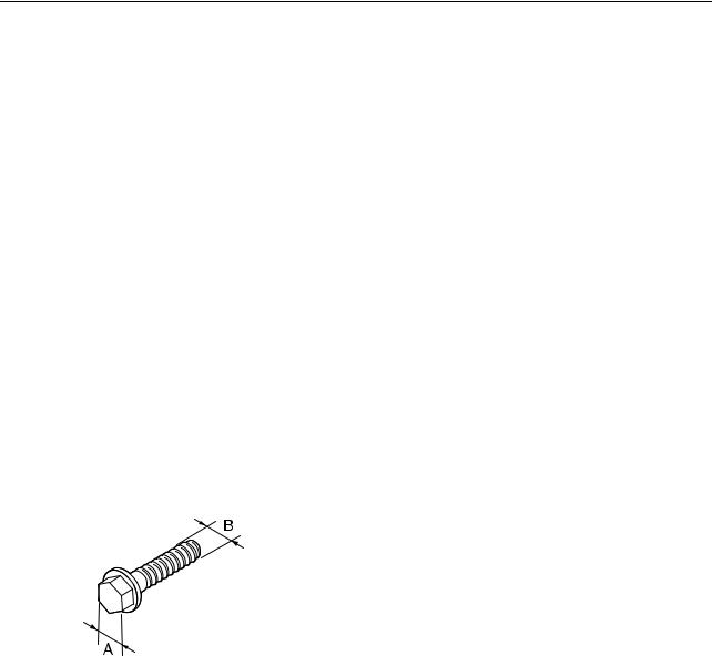
General tightening torque
This chart indicates the tightening torques for |
|
||||||
standard fasteners with a standard ISO |
|
||||||
thread pitch. Tightening torque specifications |
|
||||||
for special components and assemblies are |
|
||||||
provided in the applicable sections of this |
|
||||||
manual. To prevent warpage, tighten multi- |
|
||||||
fastener assemblies in a crisscross fashion |
|
||||||
2 |
|||||||
and progressive stages until the specified |
|||||||
torque is reached. Unless otherwise indi- |
|||||||
cated, torque specifications require clean, dry |
|||||||
threads. |
|
|
|
|
|
|
|
|
|
|
|
|
|
||
Components should be at room temperature. |
|
||||||
|
|
|
|
|
|
|
|
Width |
Screw |
General torque |
|
|
|||
across |
specifications |
|
|
||||
size (B) |
|
|
|||||
flats (A) |
N·m |
kgf·m |
ft·lb |
|
|
||
|
|
|
|||||
|
|
|
|
|
|
|
|
8 mm |
M5 |
5 |
0.5 |
3.7 |
|
|
|
10 mm |
M6 |
8 |
0.8 |
5.9 |
|
|
|
12 mm |
M8 |
18 |
1.8 |
13.3 |
|
|
|
14 mm |
M10 |
36 |
3.6 |
26.6 |
|
|
|
17 mm |
M12 |
43 |
4.3 |
31.7 |
|
|
|
|
|
|
|
|
|
|
|
2-12

SPEC
Specification
Cooling system
To stern outlet |
To exhaust |
|
outlet |
5
6 7
To pilot outlet
3


 2 4
2 4 
From flushing hose
 From jet pump
|
1 |
|
|
|
cooling water flow |
7 Water lock |
6 Exhaust outer cover 1 |
|
|
5 Exhaust chamber |
|
|
4 Exhaust ring |
|
|
3 Cylinder head |
|
|
2 Cylinder block |
|
Exhaust outlet |
1 Exhaust manifold |
Stern outlet |
|
||
Pilot outlet |
|
Flushing hose |
|
Jet pump |
|
|
Water |
|
2-13
 Loading...