


FCC INFORMATION (U.S.A.)
1.IMPORTANT NOTICE: DO NOT MODIFY THIS UNIT!
This product, when installed as indicated in the instructions contained in this manual, meets FCC requirements. Modifications not expressly approved by Yamaha may void your authority, granted by the FCC, to use the product.
2.IMPORTANT: When connecting this product to accessories and/or another product use only high quality shielded cables. Cable/s supplied with this product MUST be used. Follow all installation instructions. Failure to follow instructions could void your FCC authorization to use this product in the USA.
3.NOTE: This product has been tested and found to comply with the requirements listed in FCC Regulations, Part 15 for Class “B” digital devices. Compliance with these requirements provides a reasonable level of assurance that your use of this product in a residential environment will not result in harmful interference with other electronic devices. This equipment generates/uses radio frequencies and, if not installed and used according to the instructions found in the users manual, may cause interference harmful to the operation of other electronic devices. Compliance with FCC regulations does not guaran-
tee that interference will not occur in all installations. If this product is found to be the source of interference, which can be determined by turning the unit “OFF” and “ON”, please try to eliminate the problem by using one of the following measures:
Relocate either this product or the device that is being affected by the interference.
Utilize power outlets that are on different branch (circuit breaker or fuse) circuits or install AC line filter/s.
In the case of radio or TV interference, relocate/ reorient the antenna. If the antenna lead-in is 300 ohm ribbon lead, change the lead-in to co-axial type cable.
If these corrective measures do not produce satisfactory results, please contact the local retailer authorized to distribute this type of product. If you can not locate the appropriate retailer, please contact Yamaha Corporation of America, Electronic Service Division, 6600 Orangethorpe Ave, Buena Park, CA90620
The above statements apply ONLY to those products distributed by Yamaha Corporation of America or its subsidiaries.
* This applies only to products distributed by YAMAHA CORPORATION OF AMERICA.
NEDERLAND / NETHERLAND
•Dit apparaat bevat een lithium batterij voor geheugen back-up.
•This apparatus contains a lithium battery for memory back-up.
•Raadpleeg uw leverancier over de verwijdering van de batterij op het moment dat u het apparaat ann het einde van de levensduur afdankt of de volgende Yamaha Service Afdeiing:
Yamaha Music Nederland Service Afdeiing
Kanaalweg 18-G, 3526 KL UTRECHT
Tel. 030-2828425
•For the removal of the battery at the moment of the disposal at the end of the service life please consult your retailer or Yamaha
Service Center as follows:
Yamaha Music Nederland Service Center
Address : Kanaalweg 18-G, 3526 KL UTRECHT
Tel : 030-2828425
•Gooi de batterij niet weg, maar lever hem in als KCA.
•Do not throw away the battery. Instead, hand it in as small chemical waste.
ADVARSEL!
Lithiumbatteri—Eksplosionsfare ved fejlagtig håndtering. Udskiftning må kun ske med batteri af samme fabrikat og type. Levér det brugte batteri tilbage til leverandoren.
VARNING
Explosionsfara vid felaktigt batteribyte. Använd samma batterityp eller en ekvivalent typ som rekommenderas av apparattillverkaren. Kassera använt batteri enlight fabrikantens instruktion.
VAROITUS
Paristo voi räjähtää, jos se on virheellisesti asennettu. Vaihda paristo ainoastaan laitevalmistajan suosittelemaan tyyppiin. Hävitä käytetty paristo valmistajan ohjeiden mukaisesti.
SPECIAL MESSAGE SECTION
This product utilizes batteries or an external power supply (adapter). DO NOT connect this product to any power supply or adapter other than one described in the manual, on the name plate, or specifically recommended by Yamaha.
WARNING: Do not place this product in a position where anyone could walk on, trip over ,or roll anything over power or connecting cords of any kind. The use of an extension cord is not recommended! IF you must use an extension cord, the minimum wire size for a 25' cord (or less ) is 18 AWG. NOTE: The smaller the AWG number ,the larger the current handling capacity. For longer extension cords, consult a local electrician.
This product should be used only with the components supplied or; a cart, rack, or stand that is recommended by Yamaha. If a cart, etc., is used, please observe all safety markings and instructions that accompany the accessory product.
SPECIFICATIONS SUBJECT TO CHANGE:
The information contained in this manual is believed to be correct at the time of printing. However, Yamaha reserves the right to change or modify any of the specifications without notice or obligation to update existing units.
This product, either alone or in combination with an amplifier and headphones or speaker/s, may be capable of producing sound levels that could cause permanent hearing loss. DO NOT operate for long periods of time at a high volume level or at a level that is uncomfortable. If you experience any hearing loss or ringing in the ears, you should consult an audiologist.
IMPORTANT: The louder the sound, the shorter the time period before damage occurs.
Some Yamaha products may have benches and / or accessory mounting fixtures that are either supplied with the product or as optional accessories. Some of these items are designed to be dealer assembled or installed. Please make sure that benches are stable and any optional fixtures (where applicable) are well secured BEFORE using. Benches supplied by Yamaha are designed for seating only. No other uses are recommended.
NOTICE:
Service charges incurred due to a lack of knowledge relating to how a function or effect works (when the unit is operating as designed) are not covered by the manufacturer’s warranty, and are therefore the owners responsibility. Please study this manual carefully and consult your dealer before requesting service.
ENVIRONMENTAL ISSUES:
Yamaha strives to produce products that are both user safe and environmentally friendly. We sincerely believe that our products and the production methods used to produce them, meet these goals. In keeping with both the letter and the spirit of the law, we want you to be aware of the following:
Battery Notice:
This product MAY contain a small non-rechargeable battery which (if applicable) is soldered in place. The average life span of this type of battery is approximately five years. When replacement becomes necessary, contact a qualified service representative to perform the replacement.
This product may also use “household” type batteries. Some of these may be rechargeable. Make sure that the battery being charged is a rechargeable type and that the charger is intended for the battery being charged.
When installing batteries, do not mix batteries with new, or with batteries of a different type. Batteries MUST be installed correctly. Mismatches or incorrect installation may result in overheating and battery case rupture.
Warning:
Do not attempt to disassemble, or incinerate any battery. Keep all batteries away from children. Dispose of used batteries promptly and as regulated by the laws in your area. Note: Check with any retailer of household type batteries in your area for battery disposal information.
Disposal Notice:
Should this product become damaged beyond repair, or for some reason its useful life is considered to be at an end, please observe all local, state, and federal regulations that relate to the disposal of products that contain lead, batteries, plastics, etc. If your dealer is unable to assist you, please contact Yamaha directly.
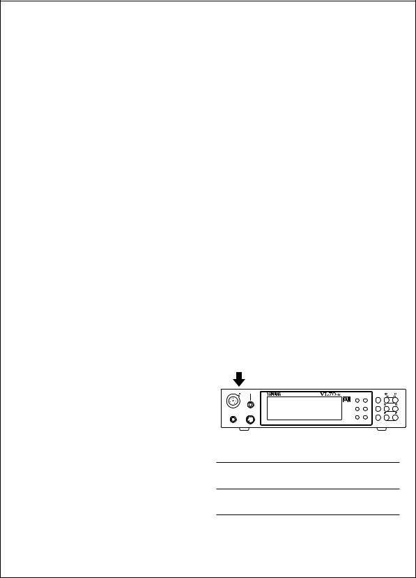
NAME PLATE LOCATION:
The name plate is located on the top of the product. The model number, serial number, power requirements, etc., are located on this plate. You should record the model number, serial number, and the date of purchase in the spaces provided below and retain this manual as a permanent record of your purchase.
WX IN |
BREATH |
|
|
MIDI/ |
PART |
|
|
VIRTUAL ACOUSTIC TONE GENERATOR |
PLAY EDIT |
||
|
|
|
WX |
ALL |
|
|
|
|
UTIL EFFECT |
ENTER |
SELECT |
|
|
|
BC/WX |
|
|
|
|
|
VELOCITY |
|
|
PHONES |
POWER/VOL |
|
TOUCH EG MODE BREATH |
EXIT |
VALUE |
|
|
|
VOICE |
|
|
|
|
|
VL-XG |
|
|
|
PART |
MIDI BANK/PGM# VOL EXP PAN REV CHO VAR KEY |
|
|
|
|
PUSH ON/OFF |
|
|
|
|
Model
Serial No.
Purchase Date
PLEASE KEEP THIS MANUAL
92-BP
* The serial number of this product is shown at the rear panel.
Thank you for choosing a Yamaha VL70-m Virtual Acoustic Tone Generator. The VL70-m is a monophonic tone generator incorporating Yamaha’s revolutionary “Virtual Acoustic Synthesis” tone generation system — based on the most advanced computer physical modeling technology. Virtual Acoustic Synthesis produces sound that is more realistic, more expressive, and more musical than any other system available at this time. The VL70-m includes 256 preset voices, from super-realistic to innovative, that can add a new dimension to your sound … whether you play a keyboard, wind controller, MIDI guitar synthesizer, or use a sequencer to create music.
Please read this owner’s manual carefully, and follow the instructions within in order to ensure proper operation. Also keep this manual in a safe place for later reference.
About the Manual
The VL70-m is a very unique tone generator that operates on totally new principles that were simply unheard of until Yamaha released the worlds first “Virtual Acoustic” synthesizer based on computer physical modelling. If you’ve had some experience with the Yamaha VL1, VL1-m, VL-7, or their “Version 2” upgrades, you will have very little trouble understanding the VL70-m. If you are new to VA synthesis, however, you will need a little background before attempting to edit and modify voices. We urge you to read the following section of this manual — “Virtual Acoustic Synthesis — before getting into the details. It will make a huge difference in how quickly you understand the VL70-m system, and how efficiently you will be able to edit voices to create the sound you’re looking for.
Other than the above, the structure of the manual is fairly straightforward. You can approach it in a “linear” manner, reading through from beginning to end, or on an “on demand” basis, going directly to the information you need as you need it. Use the table of contents at the beginning, and the index at the end of the manual to find the information you need.
Conventions
The following conventions are used through the VL70-m manuals to avoid confusion and make the text easier to read.
■ Buttons & Controls
Button and control names used on the VL70-m panel appear in the text in capital letters within square brackets: “the [ENTER] button”, for example.
■ Parameter Ranges
An ellipsis is used to indicate a range of parameter values: e.g. “0 … 127”. This minimizes the confusion sometimes caused by the use of a hyphen or dash for this purpose.
About the Manual 1

Contents
Precautions |
4 |
||
|
|
|
|
Virtual Acoustic Synthesis |
6 |
||
|
|
|
|
|
|
|
|
VA Advantages . . . . . . . . . . . . . . . . . . . . . . . 6
The VL70-m Model . . . . . . . . . . . . . . . . . . . . 7
■ The Instrument . . . . . . . . . . . . . . . . . . . 8
■ The Controllers . . . . . . . . . . . . . . . . . . . 9
■ The Modifiers . . . . . . . . . . . . . . . . . . . 10
There’s More … . . . . . . . . . . . . . . . . . . . . . . 11
The Controls & Connectors |
12 |
■ Front Panel . . . . . . . . . . . . . . . . . . . . . |
12 |
■ Rear Panel . . . . . . . . . . . . . . . . . . . . . . |
14 |
Setting Up |
15 |
Power Supply . . . . . . . . . . . . . . . . . . . . . . . . 15 MIDI Connections . . . . . . . . . . . . . . . . . . . . 16 Breath Controller . . . . . . . . . . . . . . . . . . . . . 17 WX-series Wind MIDI Controller . . . . . . . . 18 G50 Guitar MIDI Converter . . . . . . . . . . . . . 19 Connecting to a Personal Computer . . . . . 20
■ Connecting to an Apple Macintosh Series Computer . . . . . . . . . . . . . . . . . 20
■ Connecting to an IBM PC/AT Series Computer . . . . . . . . . . . . . . . . . . . . . . . 21
■ Connecting to an NEC PC-9801/9821 Series Computer . . . . . . . . . . . . . . . . . 21
Audio Connections . . . . . . . . . . . . . . . . . . . 22 ● Headphones . . . . . . . . . . . . . . . . . . 22 ● Stereo Sound System . . . . . . . . . . . 22
Power-on Procedure . . . . . . . . . . . . . . . . . . 23 Play the Demo . . . . . . . . . . . . . . . . . . . . . . . 24 The Supplied Demo Disk . . . . . . . . . . . . . . . 25 The VL70-m Voice Editing Software . . . . . 25
Voice Organization and Sound |
|
Module Modes |
26 |
Voice Organization . . . . . . . . . . . . . . . . . . . 26 The VL70-m Sound Module Modes . . . . . . 27 ■ The VOICE Mode . . . . . . . . . . . . . . . . . 27 ■ The VL-XG Mode . . . . . . . . . . . . . . . . . 28
■ Selecting the VOICE or VL-XG Sound Module Mode . . . . . . . . . . . . . . . . . . . 29
● VL Extension for XG . . . . . . . . . . . 30
The VOICE PLAY Mode |
|
31 |
The VOICE PLAY Main Control Mode |
. . . . 31 |
|
The VOICE PLAY Sub-control Mode . . |
. . . . |
34 |
The VL-XG PLAY Mode |
|
36 |
● A Simple XG System Incorporating |
|
|
the VL70-m . . . . . . . . . . . . . . . |
. . . . |
36 |
The VL-XG PLAY Main Control Mode |
. . . . 37 |
|
The VL-XG PLAY Sub-control Mode . . . |
. . . |
40 |
Controllers & Control Editing |
|
42 |
● Physical Controllers . . . . . . . . . |
. . . |
43 |
● VL70-m Controller Parameters . . . |
45 |
|
Accessing & Editing the Control |
|
|
Parameters . . . . . . . . . . . . . . . . . . . . . . . |
. . . |
46 |
The Control Edit Parameters . . . . . . . . |
. . . |
48 |
■ VOICE Sound Module Mode Control |
|
|
Edit Parameters . . . . . . . . . . . . . . . |
. . . |
48 |
■ VL-XG Sound Module Mode Control |
|
|
Edit Parameters . . . . . . . . . . . . . . . |
. . . |
50 |
■ Control Edit Parameter Descriptions . 52 |
||
● Pitch Bend . . . . . . . . . . . . . . . . |
. . . |
52 |
● Modulation Wheel . . . . . . . . . |
. . . |
53 |
● Aftertouch . . . . . . . . . . . . . . . . |
. . . |
53 |
● Assignable Controller . . . . . . . |
. . . |
54 |
● Expression . . . . . . . . . . . . . . . . |
. . . |
54 |
● Pressure . . . . . . . . . . . . . . . . . . |
. . . |
55 |
● Filter . . . . . . . . . . . . . . . . . . . . . |
. . . |
55 |
● Amplitude . . . . . . . . . . . . . . . . |
. . . |
56 |
● Embouchure . . . . . . . . . . . . . . . |
. . . |
57 |
● Tonguing . . . . . . . . . . . . . . . . . |
. . . |
58 |
● Scream . . . . . . . . . . . . . . . . . . . |
. . . |
59 |
● Breath Noise . . . . . . . . . . . . . . |
. . . |
60 |
● Growl . . . . . . . . . . . . . . . . . . . . |
. . . |
61 |
● Throat Formant . . . . . . . . . . . . |
. . . |
62 |
● Harmonic Enhancer . . . . . . . . . |
. . . |
62 |
● Damping . . . . . . . . . . . . . . . . . . |
. . . |
63 |
● Absorption . . . . . . . . . . . . . . . . |
. . . |
64 |
2 Contents

Filter & Envelope Generator Editing 66
● Amplitude & Filter EG . . . . . . . . . . |
66 |
● Pitch & Embouchre EG . . . . . . . . . |
66 |
Accessing & Editing the Filter & |
|
EG Parameters . . . . . . . . . . . . . . . . . . . . . . . |
67 |
The Filter & EG Edit Parameters . . . . . . . . |
69 |
■ VOICE Sound Module Mode Filter & |
|
EG Edit Parameters . . . . . . . . . . . . . . . |
69 |
■ VL-XG Sound Module Mode Filter & |
|
EG Edit Parameters . . . . . . . . . . . . . . . |
70 |
■ Filter & EG Edit Parameter |
|
Descriptions . . . . . . . . . . . . . . . . . . . . . |
71 |
● Filter . . . . . . . . . . . . . . . . . . . . . . . . |
71 |
● Amplitude & Filter Envelope . . . . 72 |
|
● Pitch & Embouchure Envelope . . . |
73 |
Other Edit Parameters |
75 |
Accessing & Editing the “Others” |
|
Parameters . . . . . . . . . . . . . . . . . . . . . . . . . . |
75 |
The “Others” Edit Parameters . . . . . . . . . . |
77 |
■ VOICE Sound Module Mode |
|
“Others” Edit Parameters . . . . . . . . . |
77 |
■ VL-XG Sound Module Mode |
|
“Others” Edit Parameters . . . . . . . . . |
78 |
■ “Others” Edit Parameter Descriptions 79 |
|
● Vibrato . . . . . . . . . . . . . . . . . . . . . . |
79 |
● Detune & Voice Level . . . . . . . . . . |
79 |
● Assignment & Expansion . . . . . . . |
80 |
● Velocity Sensitivity . . . . . . . . . . . . . |
81 |
● Note Limits . . . . . . . . . . . . . . . . . . . |
81 |
● Portamento . . . . . . . . . . . . . . . . . . |
82 |
● Dry Level & Voice Name . . . . . . . . |
82 |
The Store Function |
84 |
Storing an Edited Voice . . . . . . . . . . . . . . . |
84 |
Effects & Effect Editing |
86 |
|
|
|
|
Effect Signal Flow . . . . . . . . . . . . . . . . . . . . 86 ● When the Variation Stage is
an Insertion Effect . . . . . . . . . . . . . 86 ● When the Variation Stage is
a System Effect . . . . . . . . . . . . . . . 87 Accessing & Editing the Effect Parameters 88 The Reverb Parameters . . . . . . . . . . . . . . . . 90 The Chorus Parameters . . . . . . . . . . . . . . . . 91 The Variation Parameters . . . . . . . . . . . . . . 92 The Distortion Parameters . . . . . . . . . . . . . 94
Breath Settings |
95 |
Accessing & Editing the Breath Parameters 95 |
|
The Breath Parameters . . . . . . . . . . . . . . . . |
96 |
The Utility Mode |
97 |
The System Parameters . . . . . . . . . . . . . . . . 98
The Dump Out Function . . . . . . . . . . . . . . 100
● DUMPOUT Operation . . . . . . . . . 100
The Initialize Function . . . . . . . . . . . . . . . 102
Appendix |
103 |
|
|
Show Control Change . . . . . . . . . . . . . . . . 103 Show Exclusive . . . . . . . . . . . . . . . . . . . . . . 103 The Message Window . . . . . . . . . . . . . . . . 104 ● Message Window Data Format . 104 Bitmap Window . . . . . . . . . . . . . . . . . . . . . 105 ● Bitmap Window Data Format . . 105 ● Creating Bitmap Data . . . . . . . . . 105
Checksum . . . . . . . . . . . . . . . . . . . . . . . . . . 106 Troubleshooting . . . . . . . . . . . . . . . . . . . . . 107 Answers to Some Common Questions . . 110 Error Messages . . . . . . . . . . . . . . . . . . . . . . 112 Specifications . . . . . . . . . . . . . . . . . . . . . . . 113
Index |
114 |
|
|
Contents 3

Precautions !! PLEASE READ THIS BEFORE PROCEEDING !!
■ Location
Do not expose the instrument to the following conditions to avoid deformation, discoloration, or more serious damage.
•Direct sunlight (e.g. near a window).
•High temperatures (e.g. near a heat source, outside, or in a car during the daytime).
•Excessive humidity.
•Excessive dust.
•Strong vibration.
■ Power Supply
•Turn the power switch OFF when the instrument is not in use.
•The power adaptor should be unplugged from the AC outlet if the instrument is not to be used for an extended period of time.
•Unplug the instrument during electric storms.
•Avoid plugging the instrument into the same AC outlet as appliances with high power consumption, such as electric heaters or ovens. Also avoid using multi-plug adaptors since these can result in reduced sound quality and possibly damage.
■ Turn Power OFF When Making Connections
• To avoid damage to the instrument and other devices to which it is connected (a sound system, for example), turn the power switches of all related devices OFF prior to connecting or disconnecting audio and MIDI cables.
■ MIDI Connections
• When connecting the VL70-m to MIDI equipment, be sure to use highquality cables made especially for MIDI data transmission.
• Avoid MIDI cables longer than about 15 meters. Longer cables can pick up electrical noise that can causes data errors.
■ Handling and Transport
•Never apply excessive force to the controls, connectors or other parts of the instrument.
•Always unplug cables by gripping the plug firmly, not by pulling on the cable.
•Disconnect all cables before moving the instrument.
•Physical shocks caused by dropping, bumping, or placing heavy objects on the instrument can result in scratches and more serious damage.
4 Precautions

■ Cleaning
• Clean the cabinet and panel with a dry soft cloth.
• A slightly damp cloth may be used to remove stubborn grime and dirt.
• Never use cleaners such as alcohol or thinner.
■ Electrical Interference
• This instrument contains digital circuitry and may cause interference if placed too close to radio or television receivers. If this occurs, move the instrument further away from the affected equipment.
■ Data Backup
•The VL70-m contains a special long-life battery that retains the contents of its internal memory even when the power is turned OFF. The backup battery should last for several years. When the backup battery needs to be replaced “Battery Low!” will appear on the display when the power is turned on. When this happens, have the backup battery replaced by qualified Yamaha service personnel. DO NOT ATTEMPT TO REPLACE THE BACKUP BATTERY YOURSELF!
■ Service and Modification
• The VL70-m contains no user serviceable parts. Opening it or tampering with it in any way can lead to irreparable damage and possibly electric shock. Refer all servicing to qualified YAMAHA personnel.
■ Third-party Software
•Yamaha can not take any responsibility for software produced for this product by third-party manufacturers. Please direct any questions or comments about such software to the manufacturer or their agents.
YAMAHA is not responsible for damage caused by improper handling or operation.
Precautions 5

Virtual Acoustic Synthesis
Unlike previous tone generation systems which use oscillators, function generators, preset waveforms or samples to produce sound, Yamaha Virtual Acoustic (“VA”) Synthesis applies sophisticated computer-based “physical modeling” technology to musical sound synthesis. In the same way that computer “models” are used to simulate weather systems or the flight characteristics of aircraft in the design stage, the VL70-m simulates the very complex vibrations, resonances, reflections and other acoustic phenomena that occur in a real wind or string instrument.
VA Advantages
The VL70-m offers many advantages in terms of musical performance. Not just in terms of sound, but also in terms of the “behavior” that makes
acoustic instruments so … well, musical! Yamaha Virtual Acoustic Synthesis is simply the most musical tone generation system ever created.
•The VL70-m sounds better, has more depth, and is more realistic in the musical sense than any other tone generation system.
•Simply playing a note in the same way does not always produce precisely the same sound. The instrument is responsive and “alive”.
•Note-to-note transitions have the same continuity exhibited by acoustic instruments. What goes on in between the notes is just as important musically as the notes themselves.
•It has extraordinary expressive capability. Rather than simply controlling parameters like volume or pitch, you can control characteristics such as breath and reed pressure with appropriate complex effects on the timbre of the sound.
6 Virtual Acoustic Synthesis
The VL70-m Model
The overall VL70-m model or “algorithm” consists of three main blocks: the instrument, controllers, and modifiers. In schematic form these blocks
are arranged as follows:
Controllers (also envelopes) |
|
|
Instrument |
Modifiers |
Sound out |
Virtual Acoustic Synthesis |
7 |
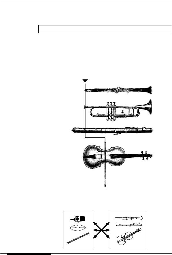
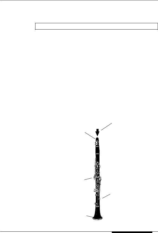
The Instrument
The key block in this algorithm is the instrument, since it is here that the fundamental tone or “timbre” of the sound is defined. The instrument model consists primarily of a driver — the reed/mouthpiece, lip/mouthpiece, or bow/ string system — and a resonant system corresponding to the tube and air column or string.
■ NOTES
•The sound thus produced is amplified and sustained by the body of the instrument.
•The pitch of the sound is determined by the length of the air column or string, and the timbre is a complex product of the driving source (reed, lip, air, string), the shape of the resonant cavity, the materials from which the instrument is made, etc.
In all these instruments pressure applied here (the driving point) causes vibration which results in sound.
Reed vibration
Lip vibration
Air vibration
String vibration
One of the remarkable features of the VL70-m’s Virtual Acoustic Synthesis system is that just about any driver can be used with any type of pipe or string.
Drivers |
Pipes/String |
8 Virtual Acoustic Synthesis
The Controllers
The input to an acoustic wind instrument comes from the player’s lungs, trachea, oral cavity, and lips. In a string instrument it comes from the player’s arm movement, transmitted to the string via a bow. These elements actually form an important part of the sound generating system and, in the VL70-m model, are included in the controllers block. The player also influences the sound of the instrument by playing the keys, tone holes, or frets, and this aspect of control constitutes another part of the controllers block. These and other control parameters provided by the VL70-m are listed in the illustration below.
In essence, the controller parameters determine how the instrument “plays”. All of these parameters can be assigned to any external controller that can be used with the VL70-m: breath controller, foot controller, modulation wheel, etc. The pressure parameter, for example, will normally be assigned to a breath controller so the player can control the dynamics of the instrument by varying the breath pressure applied to the controller — a natural, instinctive way to play windinstrument voices. At the same time the growl and throat parameters might also be assigned to the breath controller in order to achieve life-like response and effects.
Embouchure
The tightness of the lips against the reed or against each other, or the force of the bow against the string.
Tonguing
Simulates the halftonguing technique used by saxophone players by changing the “slit” of the reed.
Pitch
Changes the length of the air column or string, and thereby the pitch of the sound.
Damping & Absorption
Simulate the effects of air friction in the pipe or on the string, and of high-frequency losses at the end of the pipe or string.
Throat
Controls the characteristics of the “player’s” throat or bowing arm.
Pressure
The amount of breath pressure applied to the reed or mouthpiece, or bow velocity applied to the string.
Growl
A periodic pressure (bow velocity) modulation which produces the “growl” effect often heard in wind instruments.
Scream
Drives the entire system into chaotic oscillation, creating effects that can only be achieved with physical modelling technology.
Virtual Acoustic Synthesis |
9 |

The Modifiers
The modifiers block consists of 4 sections as shown in the diagram. Although these may appear to be simple effects, they are actually intimately related to the VL70-m’s sound-producing model and have a significant effect on the sound (the VL70-m has a separate effects stage with reverb, chorus, variation, and distortion effects — see page 86).
● Harmonic Enhancer
The Harmonic Enhancer determines the harmonic structure of the sound to the extent that it can produce radical timbral variations within an instrument “family” (e.g. saxes). The harmonic enhancer parameters can be accessed via the Yamaha VL70- m Expert Editor software (page 25).
● Dynamic Filter
This section is similar to the dynamic filters found in many conventional synthesizers, with high-pass, bandpass, band elimination, and low-pass modes. Some filter parameters are available via the VL70-m controls, but detailed editing of parameters such as the filter type requires the Yamaha VL70-m Expert Editor software (page 25)
● Frequency Equalizer
Harmonic
Enhancer
Dynamic
Filter
Frequency
Equalizer
Resonator
This is a 5-band parametric equalizer with frequency, Q (bandwidth), and level control. The equalizer also has pre-EQ highand low-pass filters as well as key scaling capability for precise response control throughout the instrument’s range. Although only simplified treble and bass parameters are available via the VL70-m controls, the full range of equalizer parameters can be accessed via the Yamaha VL70-m Expert Editor software (page 25).
● Resonator
The Resonator uses simulated “resonator” pipes or strings and delays to produce a “woody” resonance effect — although it has little or no effect on some voices. The resonator parameters can be accessed via the Yamaha VL70-m Expert Editor software (page 25).
10 Virtual Acoustic Synthesis

There’s More …
In this brief introduction to VL70-m basics we’ve only looked at the central physical model which is the key the VL70-m’s unprecedented sound and
musical performance. There’s actually much more to it. There’s also an extensive range of other functions and features that are similar to those you may be familiar with from conventional synthesizers. There are, for example, programmable envelopes that can be applied to most of the controllers in addition to real-time player control. And, of course, there’s a comprehensive selection of utility functions that give the VL70-m maximum versatility and convenience. Now that you understand the basics, dive in and find out what the VL70-m can really do.
Virtual Acoustic Synthesis 11

The Controls & Connectors
The following brief descriptions of the VL70-m controls and connectors should help you to understand the overall logic of the interface.
Front Panel
q [POWER/VOL] Control
Press to turn power ON or OFF. Rotate to adjust overall output volume (clockwise to increase the volume).
w Breath Controller Jack
An optional Yamaha BC3, BC2 or BC1 Breath Controller can be plugged in here.
page 17
e WX IN Jack
Allows direct connection of a Yamaha WXseries Wind MIDI Controller such as the WX11 or WX7, without the need for a WT11 or BT7 wind controller interface.
page 18
r PHONES Jack
Accepts a standard pair of stereo headphones (stereo mini phone plug) for headphone monitoring of the VL70-m sound without the need for external amplification equipment. The volume of the headphone sound is adjusted via the [POWER/VOL] control.
t Display
This large backlit liquid crystal display panel shows all parameters and prompts necessary for easy, efficient operation and programming of the VL70-m. The display contrast can be adjusted as described on page 99.
page 31
y [PLAY] Button
Press this button to select the VL70-m PLAY mode in which voices can be selected and played. If the PLAY mode is already selected,
pressing the [PLAY] button causes the currently selected voice to sound — a convenient test feature.
page 31
u [EDIT] Button
Activates the VL70-m EDIT mode in which voices can be edited to create new sounds.
page 46
i [UTIL] Button
Selects the VL70-m UTILITY mode. The UTILITY mode includes a range of important utility functions that affect operation of the VL70-m: SYSTEM SETUP, DUMP OUT, INITIALIZE, and DEMO SONG.
page 97
o [EFFECT] Button
Selects the VL70-m EFFECT mode in which the built-in reverb, chorus, variation, and distortion effects can be assigned and edited as required.
page 88
!0[MODE] Button
Accesses the VL70-m sound module mode selection function.
page 29
!1[BREATH] Button
Selects the BREATH SETTING which includes parameters that determine how the VL70-m responds to control from a breath controller, WX-series Wind MIDI Controller, or similar device.
page 95
12 The Controls & Connectors
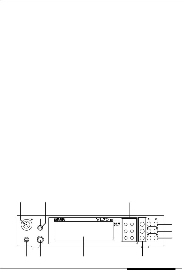
!2[MIDI/WX] Button
Pressing this button alternately selects the VL70- m MIDI and WX control modes (when the rearpanel HOST SELECT switch is set to Mac, PC- 1, PC-2).
page 18
!3[ENTER] Button
The [ENTER] button is used to engage submodes, confirm input, and execute certain operations. Double-clicking this button (i.e. press the button twice in rapid succession) provides access to the SHOW CONTROL and SHOW EXCLUSIVE (page 103) modes.
page 24
!4[EXIT] Button
This button is used to exit from sub-modes and cancel certain operations. No matter where you are in the VL70-m display structure, pressing the [EXIT] button (a number of times if necessary) will eventually return you to the PLAY mode.
page 24
!5PART [-] and [+] Buttons
When the VL-XG sound module mode is selected (page 28) these buttons select the part to be played. Either button can be pressed briefly for single stepping in the specified direction, or held for continuous scrolling. In either the VL-
e w
XG or VOICE sound module mode (page 27) pressing both buttons simultaneously switches in and out of the PLAY mode sub-control mode (pages 34 and 40).
When the EDIT mode is selected the PART buttons can be used to switch between parameters without having to return to the EDIT mode menu.
page 36
!6SELECT [<] and [>] Buttons
These buttons are used to select sub-modes or parameters. In some cases the selection will be made from a menu displays, and in others the SELECT buttons will actually switch display pages.
page 31
!7VALUE [-] and [+] Buttons
Used to select voices and edit parameter values. Either button can be pressed briefly for single stepping in the specified direction, or held for continuous scrolling. They also have a large-step function which allows you to skip ahead or backward in larger increments when selecting voices or editing numeric parameters: press either the [-] or [+] button while holding the other button.
page 31
y u i o !0!1
WX IN |
BREATH |
|
|
MIDI/ |
PART |
|
|
VIRTUAL ACOUSTIC TONE GENERATOR |
PLAY EDIT |
||
|
|
WX |
ALL |
||
|
|
|
|||
|
|
|
UTIL EFFECT |
ENTER |
SELECT |
|
|
|
BC/WX |
|
|
|
|
|
VELOCITY |
|
|
PHONES |
POWER/VOL |
|
TOUCH EG MODE BREATH |
EXIT |
VALUE |
|
|
|
VOICE |
|
|
|
|
|
VL-XG |
|
|
|
PART |
MIDI BANK/PGM# VOL EXP PAN REV CHO VAR KEY |
|
|
|
|
PUSH ON/OFF |
|
|
|
|
!5
!6
!7
r q |
t |
!2!3!4 |
The Controls & Connectors 13
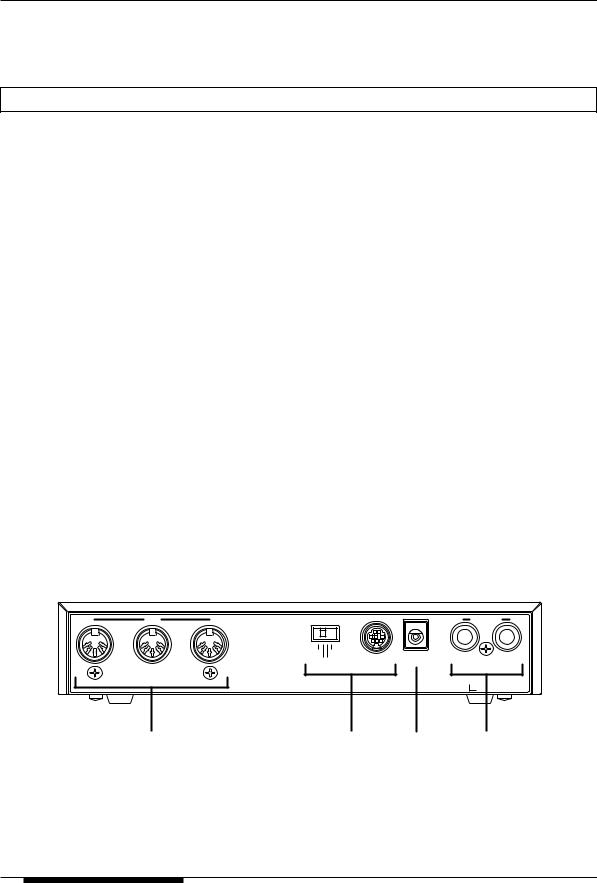
Rear Panel
!8DC IN Connector
The DC output cable from the Yamaha PA-3B AC Power Adaptor supplied with the VL70-m is plugged in here.
page 15
!9OUTPUT L/MONO and R Jacks
These are the main stereo outputs from the VL70-m. Be sure to connect both outputs to the appropriate channels of a stereo sound system in order to appreciate the full quality of the VL70- m sound and effects. The L/MONO jack can be used alone when connecting to a mono sound system (e.g. a musical instrument amplifier).
page 22
@0MIDI IN, OUT and THRU Connectors
The MIDI IN connector receives the data from an external sequencer or other MIDI device which is to control or transmit data to the VL70- m. The MIDI THRU connector simply retransmits the data received at the MIDI IN connector, allowing convenient chaining of MIDI devices. The MIDI OUT connector transmits data corresponding to VL70-m Breath Controller operation, or bulk data when one of the MIDI data transmission functions are activated. The MIDI OUT connector can also be used to “echo” (re-transmit) data received via the MIDI IN or TO HOST connectors.
page 16
@1TO HOST Connector & HOST SELECT Switch
This jack and selector switch allow direct connection to a personal computer for sequencing and other music applications — without the need for a separate MIDI interface.
page 20
|
MIDI |
HOST SELECT |
|
|
OUTPUT |
|
|
MIDI Mac |
TO HOST DC IN |
R |
L/MONO |
|
|
PC-2 PC-1 |
|||
THRU |
OUT |
IN |
|
|
|
|
|
|
SER |
NO. |
|
@0 @1 !8 !9
14 The Controls & Connectors
Setting Up
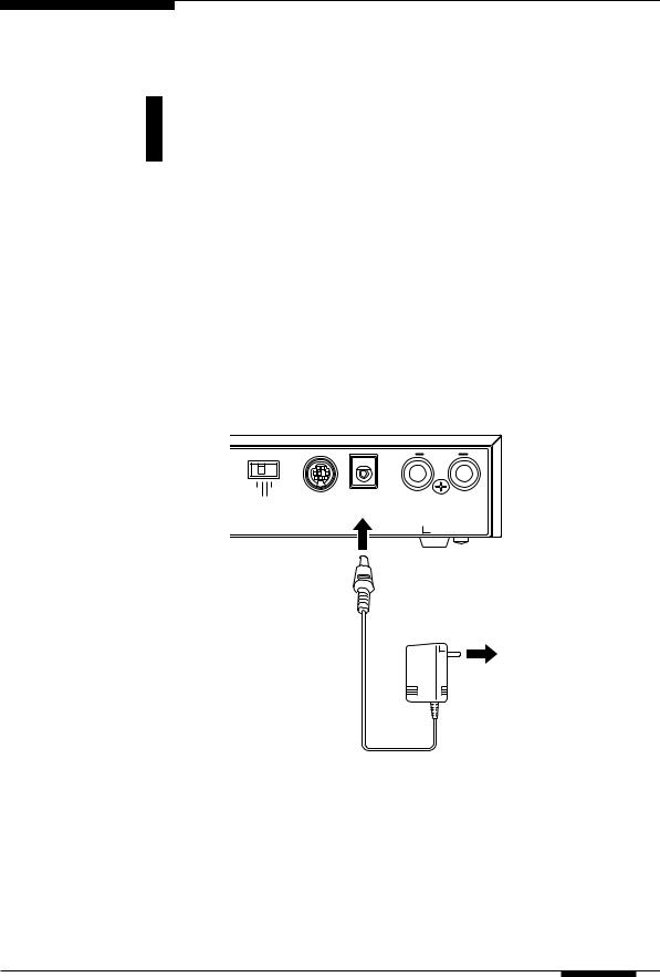
Power Supply
Your VL70-m comes supplied with a Yamaha PA-3B AC adaptor. Plug the DC output cable from the AC adaptor into the DC IN jack on the rear panel,
then plug the adaptor into a convenient wall AC power socket. It is also a good idea to clip the adaptor’s DC cable into the cable clip on the VL70-m rear panel to minimize the possibility of accidentally unplugging the cable during operation.
■ CAUTION
•Do not attempt to use an AC adaptor other than the supplied unit or an appropriate replacement provided by your Yamaha dealer to power the VL70-m. The use of an incompatible adaptor may cause irreparable damage to the VL70-m, and might pose a serious shock hazard!
•Be sure to unplug the AC adaptor from the AC mains socket when the VL70-m is not in use.
DC-IN
HOST SELECT |
|
|
OUTPUT |
MIDI Mac |
TO HOST DC IN |
R |
L/MONO |
PC-2 PC-1 |
|||
|
SER |
NO. |
|
PA-3B
AC power socket
Setting Up 15
MIDI Connections
The VL70-m can be used with virtually any type of MIDI controller: keyboard, wind controller, sequencer, etc. To ensure reliable error-free transfer of MIDI data always use high-quality MIDI cables obtained from your Yamaha
dealer or music equipment store. Also avoid MIDI cables that are longer than about 15 meters, since cables longer than this can pick up noise which can cause data errors.
The VL70-m MIDI receive channel and device number parameters are available via the PLAY mode display and PLAY mode sub-control display (pages 32 and 34). Make sure these parameters are set to match the corresponding settings of the MIDI controller used with the VL70-m.
● The VL70-m receives the following MIDI data:
Note |
The played note and velocity values. |
|
|
Control Change |
Modulation wheel, breath controller, foot controller, sustain, and |
|
other controller data. |
|
|
Aftertouch |
Keyboard aftertouch pressure (channel aftertouch only). |
|
|
Pitch Bend |
Pitch bend wheel position. |
Program Change Voice numbers and bank select messages.
& Bank Select
System Exclusive Voice and system data transmitted in the form of “bulk dumps.”
■ NOTES
•IMPORTANT!: The rear-panel HOST SELECT switch must be set to “MIDI” when the VL70- m is not connected to a computer via the TO HOST connector.
•For detailed MIDI specifications refer to the “MIDI Data Format” on page 26 of the List Book.
•When using the VL70-m with other MIDI equipment, it is a good idea to refer to the MIDI specifications (implementation chart, MIDI data format) of the equipment used to ensure compatibility.
16 Setting Up
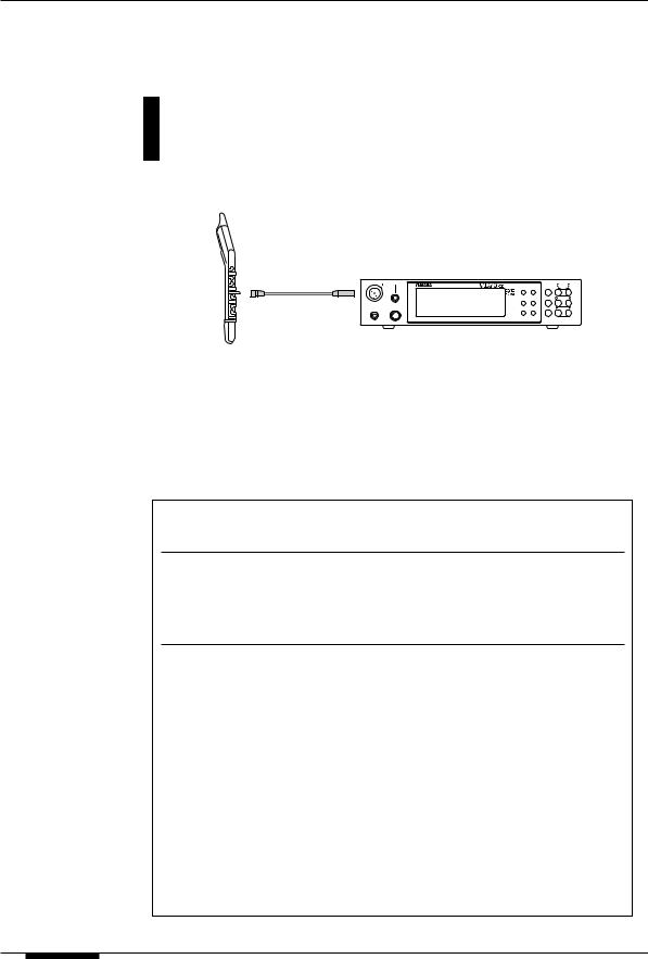
Breath Controller
If you will be using the VL70-m with a keyboard, a breath controller is an essential expressive tool — both for realistic expression with wind-instru- ment voices and unprecedented expressive control with string voices. Plug an
optional Yamaha BC3, BC2 or BC1 Breath Controller into the front-panel breath controller jack. If the controlling MIDI keyboard has a breath controller jack, it might be more convenient to plug the breath contoller in there rather than directly into the VL70-m. The Breath Controller is ideal for controlling parameters that would normally be affected by a wind player’s breath: dynamics, timbre, pitch, and others.
■ IMPORTANT!
•If you will be using a BC3, BC2, or BC1 breath controller plugged into the BREATH jack, the “Breath Mode” parameter must be set to “BC/WX” (page 96). This is also necessary if you plug the breath controller into the keyboard’s breath controller jack.
MIDI OUT
MIDI keyboard
|
|
|
|
MIDI IN |
|
|
|
WX IN |
BREATH |
|
|
MIDI/ |
PART |
|
|
|
VIRTUAL ACOUSTIC TONE GENERATOR |
PLAY EDIT |
||
|
|
|
|
WX |
ALL |
|
|
|
|
|
UTIL EFFECT |
ENTER |
SELECT |
|
|
|
|
BC/WX |
|
|
BREATH |
|
|
|
VELOCITY |
|
|
PHONES |
POWER/VOL |
|
TOUCH EG MODE BREATH |
EXIT |
VALUE |
|
|
|
|
VL-XG |
|
|
|
|
|
|
|
VOICE |
|
|
|
|
PART |
MIDI BANK/PGM# VOL EXP PAN REV CHO VAR KEY |
|
|
|
|
|
PUSH ON/OFF |
|
|
|
|
BC3 |
|
|
VL70-m |
|
|
|
|
|
|
|
|
|
|
Setting Up 17
WX-series Wind MIDI Controller
The VL70-m is an ideal tone generator for use with a Yamaha WX-series Wind MIDI Controller such as the WX11 or WX7. In either case the con-
troller can be plugged directly into the WX IN connector on the VL70-m front panel, without the need for a WT11 or BT7 wind controller interface.
WX IN
WX11
WX IN |
BREATH |
|
|
MIDI/ |
PART |
|
|
VIRTUAL ACOUSTIC TONE GENERATOR |
PLAY EDIT |
||
|
|
|
WX |
ALL |
|
|
|
|
UTIL EFFECT |
ENTER |
SELECT |
|
|
|
BC/WX |
|
|
|
|
|
VELOCITY |
|
|
PHONES |
POWER/VOL |
|
TOUCH EG MODE BREATH |
EXIT |
VALUE |
|
|
|
VOICE |
|
|
|
|
|
VL-XG |
|
|
|
PART |
MIDI BANK/PGM# VOL EXP PAN REV CHO VAR KEY |
|
|
|
|
PUSH ON/OFF |
|
|
|
|
VL70-m
Special care must be taken with the following parameters and controls when using a WX-series Wind MIDI Controller:
■ NOTES
•If a WX controller is unplugged while the VL70-m power is on, the breath level may remain fixed at “0” and subsequently played notes may not sound. If this happens, turn the VL70-m power off and then on again.
BREATH MODE The Breath Mode parameter (page 96) must be set to “BC/WX” in order for the VL70-m to recognize breath data from the controller.
SOUND MODULE If you intend to drive additional MIDI devices via the VL70-m MODE MIDI OUT connector when using a Wind MIDI Controller, the
VL70-m sound module mode should be set to VOICE (page 29). When the VL-XG mode is selected MIDI note data received via the MIDI IN connector is not re-transmitted via the MIDI OUT connector.
LIP MODE |
WX-series Wind MIDI Controllers produce pitch bend data |
|
ranging from “-16” to “+32” in response to lip (reed) pressure. |
|
The WX Lip parameter (page 98) determines whether these |
|
values are used as is (“Norm”), or expanded to a “-64” through |
|
“+63” range (“Expd”). When the “Expd” mode is selected, the |
|
expanded pitch bend data is also transmitted via the MIDI OUT |
|
connector. The “Expd” setting is recommended when using a |
|
WX controller in the “tight lip” mode. The “Norm” setting is |
|
recommended when using the WX controller “loose lip” mode. |
|
|
MIDI/WX |
When the VL70-m is connected to a WX controller and a |
SETTING |
computer via the TO HOST connector, and the HOST SELECT |
|
switch is set to any position other than “MIDI”, the front-panel |
|
[MIDI/WX] button must be used to select the “WX” mode (a |
|
small WX icon will appear on the left side of the display) in |
|
order for the VL70-m to recognize data from the WX controller. |
|
When the HOST SELECT switch is set to “MIDI” the VL70-m |
|
accepts both MIDI and WX data (both the MIDI and WX icons |
|
appear on the display), and the [MIDI/WX] button has no effect. |
18 Setting Up
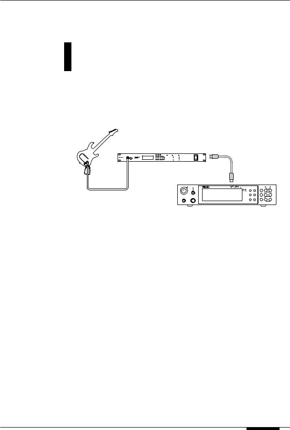
G50 Guitar MIDI Converter
The Yamaha G50 is a high-performance Guitar MIDI Converter designed to work in conjunction with the Yamaha G1D Divided Pickup Unit installed on
an electric or steel-string acoustic guitar. The G50 offers unprecedented MIDI guitar synthesizer performance with exceptionally fast response and a range of advanced features that bring the true creative potential of MIDI control to guitar players for the first time. Naturally, the VL70-m is an ideal tone generator for use with a MIDI guitar system based on the G50.
Guitar
G50 |
MIDI OUT |
GUITAR MIDI CONVERTER
G1D
|
|
|
MIDI IN |
|
|
WX IN |
BREATH |
|
|
MIDI/ |
PART |
|
|
VIRTUAL ACOUSTIC TONE GENERATOR |
PLAY EDIT |
||
|
|
|
WX |
ALL |
|
|
|
|
UTIL EFFECT |
ENTER |
SELECT |
|
|
|
BC/WX |
|
|
|
|
|
VELOCITY |
|
|
PHONES |
POWER/VOL |
|
TOUCH EG MODE BREATH |
EXIT |
VALUE |
|
|
|
VOICE |
|
|
|
|
|
VL-XG |
|
|
|
PART |
MIDI BANK/PGM# VOL EXP PAN REV CHO VAR KEY |
|
|
|
|
PUSH ON/OFF |
|
|
|
|
VL70-m
Since the G50 produces MIDI output, the standard MIDI connection rules that apply to a keyboard or any other MIDI controller also apply when connecting the G50 to the VL70-m (page 16).
Setting Up 19
●Connector Pin Numbers
mini Din 8-pin
6 7 8
3 4 5
1 2
D-SUB 9-pin
5 4 3 2 1
9 8 7 6
D-SUB 25-pin
1 |
2 |
3 |
4 |
5 |
6 |
7 |
8 |
9 10 11 12 13 |
14 15 16 17 18 19 20 21 22 23 24 25
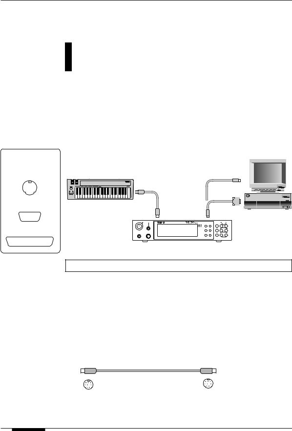
Connecting to a Personal Computer
Although the VL70-m can be connected to a personal computer via the MIDI IN/OUT connectors and a MIDI interface, the TO HOST connector
and selector switch allow direct connection to Apple Macintosh, IBM PC/AT, or NEC PC-9801/9821 series personal computers for sequencing and other music applications without the need for a separate MIDI interface.
■ IMPORTANT!
•If the VL70-m is to be connected to a computer via the TO HOST connector and a MIDI controller via the MIDI IN connector, the “echo back” function of the music software or sequencer you are using must be turned “on” so that the MIDI note data from the controller is returned to the VL70-m and any subsequent devices connected to the VL70- m MIDI OUT connector.
|
|
|
Modem or |
|
|
|
MIDI controller |
|
Printer port |
|
|
||
MIDI OUT |
|
|
|
PS/V |
Personal System/V |
|
|
|
|
|
RS-232C |
|
Personal System/V |
|
|
|
|
IBM |
|
|
|
MIDI IN |
TO HOST |
|
Personal |
||
WX IN |
BREATH |
PLAY EDIT |
WX |
ALL |
|
computer |
|
VIRTUAL ACOUSTIC TONE GENERATOR |
|
MIDI/ |
PART |
|
|
|
|
UTIL EFFECT |
ENTER |
SELECT |
|
|
|
|
BC/WX |
|
|
|
|
|
|
VELOCITY |
|
|
|
|
PHONES |
POWER/VOL |
TOUCH EG MODE BREATH |
EXIT |
VALUE |
|
|
VOICE
VL-XG
PART |
MIDI |
BANK/PGM# VOL EXP PAN REV CHO VAR KEY |
PUSH ON/OFF |
|
|
VL70-m
Connecting to an Apple Macintosh Series Computer
Connect the TO HOST connector of the VL70-m to the modem or printer port on your Macintosh, depending on which port your MIDI software is using for MIDI data communication, using a standard Macintosh 8-pin system peripheral cable. Set the TO HOST selector to the “Mac” position.
You may also have to make other MIDI interface settings on the computer side, depending on the type of software you use (refer to your software owner’s manual). In any case the clock speed should be set to 1 MHz.
● “Mac” Cable Connections
mini Din 8-pin |
mini Din 8-pin |
•8-pin system peripheral cable.
•Data transfer rate: 31,250 bps.
20 Setting Up

Connecting to an IBM PC/AT Series Computer
Connect the TO HOST connector of the VL70-m to the RS-232C port on your IBM computer, using a standard 8-pin MINI DIN → 9-pin D-SUB cross cable. Set the TO HOST selector to the “PC-2” position.
Refer to your software owner’s manual for information on any settings you might have to make on the computer side.
● “PC-2” Cable Connections
|
|
|
|
|
|
|
|
|
|
|
|
|
|
|
|
|
|
|
|
|
|
|
|
mini Din 8-pin |
D-SUB 9-pin |
||||
•8-pin mini DIN → 9-pin D-SUB cable. Use a “PC-1” type cable if your computer uses a 25-pin serial port.
•Data transfer rate: 38,400 bps.
Connecting to an NEC PC-9801/9821 Series Computer
The NEC PC-9801/9821 computers are widely used in Japan. Connect the TO HOST connector of the VL70-m to the RS-232C port on your NEC computer, using a standard 8-pin MINI DIN → 25-pin D-SUB cross cable. Set the TO HOST selector to the “PC-1” position.
Refer to your software owner’s manual for information on any settings you might have to make on the computer side.
■ NOTES
•If your system doesn’t work properly with the connections and settings listed above, your software may require different settings. Check your software operation manual and set the HOST SELECT switch to the position the provides the appropriate data transfer rate.
●“PC-1” Cable Connections
|
|
|
|
|
|
|
|
|
|
|
|
|
|
|
|
|
|
|
|
|
|
|
|
|
|
|
|
|
|
mini Din 8-pin |
D-SUB 25-pin |
||||
•8-pin mini DIN → 25-pin D-SUB cable. Use a “PC-2” type cable if your computer uses a 9-pin serial port.
•Data transfer rate: 31,250 bps.
Setting Up 21

Audio Connections
■ Headphones
For private listening and practice headphones are ideal. You don’t have to hook up and complete sound system, and you won’t disturb the neighbors no matter how loud or late you play. Any standard pair of stereo headphones with a stereo mini phone plug and an impedance of between about 8 and 150 ohms can be used.
■ Stereo Sound System
The VL70-m voices and effects are designed to sound their best in stereo, so you should always use a stereo sound system to appreciate the full impact of the VL70-m voices and expressive features. The VL70-m OUTPUT L/MONO and R jacks can be connected directly to musical instrument amplifiers designed for keyboard use, or to the line inputs of a mixing console. It is also possible to connect the VL70-m outputs directly to the inputs of a multitrack or stereo tape recorder.
■ NOTES
•If you need to drive a mono amp or other device, connect only the L/MONO output jack. The left and right channel signals are automatically combined and delivered via the L/ MONO jack when a single phone plug is inserted in this jack and the R output jack is left unconnected.
•Make sure that both the VL70-m and your sound system are turned OFF when making connections.
22 Setting Up

Power-on Procedure
Always follow proper procedure when powering-up a sound system to minimize the possibility of damage to the equipment (and your ears!).
1.Make sure your sound system’s main level/volume control(s) and the VL70-m volume control are turned all the way down prior to turning power on.
2.Turn on the VL70-m.
3.Turn on your MIDI controller (and computer/sequencer, if used).
4.Turn on the sound system.
5.Raise the sound system volume to a reasonable level.
6.Gradually raise the VL70-m VOLUME control while playing the MIDI controller to set the desired listening level.
■ NOTES
•Some keyboards and other MIDI controllers automatically transmit MIDI control change data corresponding to their control status when the power switch is turned ON or OFF. The VL70-m is programmed to receive this data and respond accordingly, so it is preferable to turn the VL70-m ON before turning the controlling device ON.
Setting Up 23

Play the Demo
Once you’ve set up your VL70-m system, you might like to play the preprogrammed demo sequence to hear how some of the voices sound. This process will also help to familiarize you with some of the VL70-m’s selection
and editing procedures.
■ NOTES
•When the demo is played all system setup parameters and current voice are initialized. If your VL70-m memory contains data you want to keep, be sure to use the bulk dump function (page 100) to save the data to an external MIDI data recorder or other appropriate storage device before playing the demo.
1.Select the Utility Mode
Press the [UTILITY] button to select the utility mode.
2.Select the Demo Mode
Use the SELECT [<] and [>] buttons to select the “DEMO” mode.
3.Press [ENTER] and Confirm
Press the [ENTER] button if it’s OK to go ahead with the demo. The VL70- m will ask you to confirm: press [ENTER] again to proceed to the demo song select display, or [EXIT] to abort.
4.Select a Song
Use the VALUE [-] and [+] buttons to select the demo song number you want to start with.
5.Run the Demo
Press the [ENTER] button to run the demo. Playback will start with the selected song, then all other songs will be played in sequence. The cycle will repeat until stopped.
6.Stop the Demo
Press the [EXIT] button to stop demo playback. This will return you to the demo song select display.
7.Return To the Play Mode When Done
Press the [PLAY] button to return to the PLAY mode.
24 Setting Up

The Supplied Demo Disk
The VL70-m is supplied with a demonstration data disk which contains several songs which demonstrate some of the VL70-m’s advanced musical
capabilities. The songs on this disk can be reproduced using any sequencer or computer-based sequence software which can handle SMF (Standard MIDI File
— format 0) song files.
All of the demo songs use the VL70-m for the main melody line, while a second XG tone generator (Yamaha MU50 or MU80 for example) supplies the backing.
■ NOTES
•The supplied disk is a 2DD type (720 kilobytes) using MS-DOS format. The disk can be read by Macintosh computers by using the PC Exchange application and an application such as ResEdit which can change the file’s file type.
The VL70-m Voice Editing Software
— What It Is & Where To Get It —
The range of parameters accessible via the VL70-m programming interface is limited to the simplest “upper level” of virtual acoustic synthesis parameters. The “core” parameters which are the true foundation of physical modeling are extremely complex, and were therefore not made directly accessible.
The VL70-m Expert Editor voice editing software provides full access to the complete range of physical modeling parameters. It can be used alone to create new voices, or edit voices loaded from the VL70-m. The VL70-m Expert Editor is basically a refined version of the editing software Yamaha voicing professionals use to create original voices for VL-series synthesizers and tone generators. It therefore gives you full professional-level programming power and potential. Another handy VL editing software is the VL Visual Editor. The VL Visual Editor makes it easy for anyone to create new VL voices via a graphic, easy-to- use editing interface. The VL70-m Expert Editor can read voice files created by the VL Visual Editor, allowing further in-depth programming.
The VL Voice Editing Software can be obtained via Yamaha’s XG
home page on the World Wide Web, “http://www.yamaha.co.jp./english/xg/html/ libhm.html”.
Setting Up 25

Voice Organization and Sound Module
Modes
Voice Organization
The VL70-m voices are organized into four main banks. Additional banks are used when the VL70-m is set to operate in the VL-XG sound module
mode (page 29). The four main banks are as follows:
|
PRESET 1 |
The PRESET 1 bank contains 128 preset voices which have been |
|
|
|
created primarily to be played via a keyboard. |
|
|
|
|
|
|
PRESET 2 |
The PRESET 2 bank contains 128 preset voices which have been |
|
|
|
created to provide maximum expressive capability when played |
|
|
|
with a breath controller or WX-series Wind MIDI Controller. |
|
|
|
|
|
|
CUSTOM |
The CUSTOM bank has 6 memory locations in which voices can |
|
|
|
be edited in detail via an appropriate personal computer and |
|
|
|
the Yamaha VL70-m Expert Editor application software (page |
|
|
|
25). When the VL70-m is initially shipped CUSTOM voice num- |
|
|
|
bers 001 through 006 contain a selection of sound-effect type |
|
|
|
voices from the PRESET banks. |
|
|
|
|
|
|
INTERNAL |
The INTERNAL bank has 64 memory locations in which voices |
|
|
|
you have edited can be stored and easy recalled for use as |
|
|
|
required. Unlike CUSTOM voices, INTERNAL voices can be edited |
|
|
|
via the VL70-m panel controls. When the VL70-m is initially |
|
|
|
shipped INTERNAL voice numbers 001 through 064 contain a |
|
|
|
selection of voices from the PRESET 1 and PRESET 2 banks, set |
|
|
|
up to be played via a WX-series Wind MIDI Controller. |
|
|
|
|
|
Banks 112 through 119 become available when the VL70-m is set to the VL-XG sound module mode (page 29). In the VL-XG sound module mode some voices from the PRESET 1 and PRESET 2 banks are assigned MIDI bank and program change numbers conforming to the Yamaha XG format. Since the VL70-m does not have a full set of XG-compatible voices, however, some voice numbers will be skipped (e.g. 23, 24, 27, etc.).
■ NOTES
• PRESET 1, PRESET 2, and CUSTOM voices can be edited via the VL70-m panel controls, but the edited voices cannot be stored to the PRESET 1, PRESET 2, or CUSTOM bank. Edited voices can only be stored to the INTERNAL bank, and only when the VL70-m is set to the VOICE sound module mode (page 29).
• The factory preset CUSTOM and INTERNAL |
|
|
|
|
|
|
BANK |
MSB |
LSB |
|
|
voices can be restored by using the Factory Set |
|
|
|||
Initialize function described on page 102. |
|
PRESET 1 |
33 |
0 |
|
• Refer to the separate “List Book” for a com- |
|
PRESET 2 |
33 |
1 |
|
|
CUSTOM |
33 |
2 |
|
|
plete listing of the VL70-m voices. |
|
|
|||
|
INTERNAL |
33 |
3 |
|
|
• Use the MIDI bank MSB (control number 00) |
|
|
|||
|
BANK 112 |
97 or 81 |
112 |
|
|
and LSB (control number 32) numbers listed at |
|
BANK 113 |
97 or 81 |
113 |
|
right to select VL70-m banks from an external |
|
BANK 114 |
97 or 81 |
114 |
|
MIDI device. In the VOICE sound module mode, |
|
BANK 115 |
97 or 81 |
115 |
|
|
BANK 116 |
97 or 81 |
116 |
|
|
the MSB is ignored (recognized as 33) and only |
|
|
|||
|
BANK 117 |
97 or 81 |
117 |
|
|
LSB numbers 0 through 3 are recognized. |
|
|
|||
|
BANK 118 |
97 or 81 |
118 |
|
|
|
|
|
|||
|
|
BANK 119 |
97 or 81 |
119 |
|
|
|
|
|
|
|
26 Voice Organization and Sound Module Modes
 Loading...