


 Loading...
WaveRunner
FX SHO
FX Cruiser SHO
SERVICE MANUAL
*LIT186160312*
LIT-18616-03-12 |
F1W-28197-1K-11 |
E
NOTICE
This manual has been prepared by Yamaha primarily for use by Yamaha dealers and their trained mechanics when performing maintenance procedures and repairs to Yamaha equipment. It has been written to suit the needs of persons who have a basic understanding of the mechanical and electrical concepts and procedures inherent in the work, for without such knowledge attempted repairs or service to the equipment could render it unsafe or unfit for use.
Because Yamaha has a policy of continuously improving its products, models may differ in detail from the descriptions and illustrations given in this publication. Use only the latest edition of this manual. Authorized Yamaha dealers are notified periodically of modifications and significant changes in specifications and procedures, and these are incorporated in successive editions of this manual.
Important information
Particularly important information is distinguished in this manual by the following notations:
The Safety Alert Symbol means ATTENTION! BECOME ALERT! YOUR SAFETY IS INVOLVED!

 WARNING
Failure to follow WARNING instructions could result in severe injury or death to the machine operator, passengers, a bystander, or a person inspecting or repairing the watercraft.
CAUTION:
A CAUTION indicates special precautions that must be taken to avoid damage to the watercraft.
NOTE:
A NOTE provides key information to make procedures easier or clearer.
WaveRunner
FX SHO, FX Cruiser SHO
SERVICE MANUAL
©2007 by Yamaha Motor Corporation, USA 1st Edition, December 2007
All rights reserved.
Any reprinting or unauthorized use without the written permission of Yamaha Motor Corporation, USA is expressly prohibited.
Printed in USA
LIT-18616-03-12

|
|
|
|
E |
|||||
|
|
|
|
|
|
|
|
|
|
Contents |
|
|
|
|
|
|
|
|
|
|
|
|
|
|
|
|
|
|
|
General information |
|
|
|
|
|
|
|
|
|
|
GEN |
||||||||
|
INFO |
||||||||
|
|
|
|
|
|
|
|
|
|
Specification |
|
|
|
|
|
|
|
|
|
SPEC |
|||||||||
|
|||||||||
|
|
|
|
|
|
|
|
|
|
|
|
|
|
|
|
|
|
|
|
Periodic check and adjustment |
|
|
|
|
|
|
|
|
|
|
CHK |
||||||||
|
|
ADJ |
|||||||
|
|
|
|
|
|
|
|
|
|
Fuel system |
|
|
|
|
|
|
|
|
|
|
|
|
|
|
|
|
|
||
FUEL |
|||||||||
|
|||||||||
|
|
|
|
|
|
|
|
|
|
|
|
|
|
|
|
|
|
|
|
Power unit |
|
|
|
|
|
|
|
|
|
|
|
|
|
|
|
|
|
||
|
|
|
|
|
|
|
|
||
POWR |
|||||||||
|
|||||||||
|
|
|
|
|
|
|
|
|
|
|
|
|
|
|
|
|
|
|
|
Jet pump unit |
|
|
|
|
|
|
|
|
|
|
JET |
||||||||
|
PUMP |
||||||||
|
|
|
|
|
|
|
|
|
|
|
|
|
|
|
|
|
|||
|
|
– + |
|
||||||
Electrical system |
|
|
|
|
|
|
|
|
|
|
|
|
|
|
|
|
|
||
ELEC |
|||||||||
|
|||||||||
|
|
|
|
|
|
|
|
|
|
|
|
|
|
|
|
|
|
|
|
Hull and hood |
|
|
|
|
|
|
|
|
|
HULL |
|||||||||
|
HOOD |
||||||||
|
|
|
|
|
|
|
|
|
|
Trouble analysis |
|
|
|
|
|
|
|
|
|
TRBL |
|||||||||
|
ANLS |
||||||||
1
2
3
4
5
6
7
8
9

GEN INFO
E
Chapter 1
General information
How to use this manual ................................................................................. |
1-1 |
Manual format............................................................................................ |
1-1 |
Symbols..................................................................................................... |
1-2 |
Abbreviation............................................................................................... |
1-3 |
Grease table .............................................................................................. |
1-3 |
Safety while working...................................................................................... |
1-4 |
Fire prevention........................................................................................... |
1-4 |
Ventilation.................................................................................................. |
1-4 |
Self-protection ........................................................................................... |
1-4 |
Parts, lubricants, and sealants .................................................................. |
1-4 |
Good working practices ............................................................................. |
1-5 |
Disassembly and assembly ....................................................................... |
1-5 |
Identification number..................................................................................... |
1-6 |
Primary l.D. number................................................................................... |
1-6 |
Engine serial number................................................................................. |
1-6 |
Jet pump unit serial number ...................................................................... |
1-6 |
Hull identification number (H.l.N.).............................................................. |
1-6 |
Special service tool ....................................................................................... |
1-7 |
Measuring.................................................................................................. |
1-7 |
Removal and installation ........................................................................... |
1-9 |
Feature and benefit ...................................................................................... |
1-14 |
Watercraft overview................................................................................. |
1-14 |
Engine overview ...................................................................................... |
1-15 |
Air filter case and air filter element .......................................................... |
1-16 |
Supercharger assembly........................................................................... |
1-16 |
Air cooler assembly ................................................................................. |
1-17 |
Intake system .......................................................................................... |
1-17 |
Electronic control throttle valve (ETV) system......................................... |
1-18 |
Cylinder head assembly .......................................................................... |
1-19 |
Hydraulic timing chain tensioner.............................................................. |
1-19 |
Ignition coil............................................................................................... |
1-20 |
Piston and connecting rod ....................................................................... |
1-20 |
Cylinder block and crankcase.................................................................. |
1-21 |
Knock sensor........................................................................................... |
1-21 |
Lubrication system................................................................................... |
1-22 |
Oil pump assembly .................................................................................. |
1-23 |
Oil pan ..................................................................................................... |
1-24 |
Oil separator tank .................................................................................... |
1-25 |
Oil cooler assembly ................................................................................. |
1-25 |
Oil filter .................................................................................................... |
1-26 |
Exhaust system ....................................................................................... |
1-26 |
Cooling system ........................................................................................ |
1-27 |

GEN |
|
|
|
|
|
|
INFO |
|
|
|
E |
||
|
|
|
|
|
|
|
|
Water cooled rectifier regulator ............................................................... |
1-28 |
|
|
|
|
|
In-tank fuel pump module ........................................................................ |
1-29 |
|
|
|
|
|
Large intermediate housing and oil seal.................................................. |
1-30 |
|
|
|
|
|
|
|
1 |
|||
|
Intake grate.............................................................................................. |
1-30 |
|
|
||
|
Reverse gate assembly ........................................................................... |
1-31 |
|
|
||
|
QSTS....................................................................................................... |
1-31 |
|
|
||
|
Multifunction meter .................................................................................. |
1-32 |
|
|||
|
Right multifunction display (FX Cruiser SHO) ................................... |
1-35 |
|
|
|
|
|
...................Average speed, tripmeter, and trip time measurements |
1-36 |
|
|
|
|
|
Electrical system...................................................................................... |
1-37 |
|
|
|
|
|
Yamaha diagnostic system (YDIS) ................................................... |
1-37 |
|
|
|
|
|
Cruise assist and no-wake mode ...................................................... |
1-37 |
|
|
|
|
|
Slant detection switch ....................................................................... |
1-38 |
|
|
|
|
|
Off-throttle steering (OTS) system .................................................... |
1-39 |
|
|
|
|
|
L-MODE (low-rpm mode) and yamaha security system ................... |
1-39 |
|
|
|
|
|
Remote control transmitter................................................................ |
1-41 |
|
|
|
|
Technical tips ............................................................................................... |
1-42 |
|
|
|
||
|
Engine control.......................................................................................... |
1-42 |
|
|
|
|
|
Cruise assist control.......................................................................... |
1-43 |
|
|
|
|
|
No-wake mode control ...................................................................... |
1-44 |
|
|
|
|
|
Reverse with traction control............................................................. |
1-45 |
|
|
|
|
|
Idle speed control.............................................................................. |
1-45 |
|
|
|
|
|
Over revolution control ...................................................................... |
1-45 |
|
|
|
|
|
L-MODE (LOW-RPM MODE) control................................................ |
1-45 |
|
|
|
|
|
Slant detection control....................................................................... |
1-45 |
|
|
|
|
|
High intake air pressure control ........................................................ |
1-46 |
|
|
|
|
|
Knock control .................................................................................... |
1-46 |
|
|
|
|
|
Off-throttle steering (OTS) control ........................................................... |
1-47 |
|
|
|
|
|
Remote control transmitter control .......................................................... |
1-48 |
|
|
|
|
|
Warning control ....................................................................................... |
1-49 |
|
|
|
|
|
Overheat warning control .................................................................. |
1-49 |
|
|
|
|
|
Oil pressure warning control ............................................................. |
1-49 |
|
|
|
|
|
ETV failure control............................................................................. |
1-49 |
|
|
|
|
|
Cam position sensor failure control................................................... |
1-50 |
|
|
|
|
|
Battery disconnection warning .......................................................... |
1-50 |
|
|
|
|
|
Fail-safe function table ............................................................................ |
1-51 |
|
|
|
|
GEN INFO
How to use this manual |
E |
|
How to use this manual
Manual format
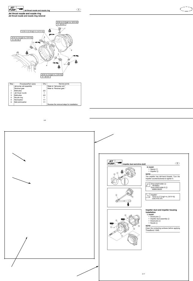
The format of this manual has been designed to make service procedures clear and easy to understand. Use the information below as a guide for effective and quality service.
•Parts are shown and detailed in an exploded diagram and are listed in the component list (refer to 1 in the figure below for an example page).
•The component list consists of part names and quantities (refer to 2 in the figure below).
•Symbols are used to indicate important aspects of a procedure, such as the grade of lubricant and lubrication point (refer to 3 in the figure below).
•Tightening torque specifications are provided in the exploded diagrams (refer to 4 in the figure below for an example), and in the related detailed instructions. Some torque specifications are listed in stages as torque figures or angles in degrees.
•Separate procedures and illustrations are used to explain the details of removal, checking, and installation where necessary (refer to 5 in the figure below for an example page).
NOTE:
For troubleshooting procedures, refer to “Trouble analysis” in Chapter 9.
1
4
3
2
5
1-1
|
GEN |
|
|
|
|
|
|
|
|
|
|
|
|
|
|
|
|
INFO |
|
|
|
|
How to use this manual |
E |
|
|
|||||||
|
|
|
|
|
|
|
|
|
|
|
|
|
|
Symbols |
|
|
1 |
|
|
|
|
2 |
|
|
|
|
|
|
|||||
|
|
|
|
|
|
|
|
|
|
|
|
|
|
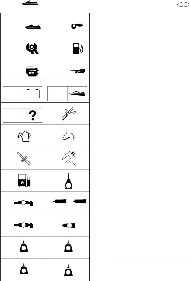
Symbols 1 to 9 are designed to indicate the |
|
|
|
GEN |
|
|
|
|
|
|
|
|
|
|
|
|
|||
|
|
|
|
|
|
SPEC |
|
|
|
|
|
content of a chapter. |
|
|||
|
INFO |
|
|
|
|
|
|
|
|
|
1 |
|||||
|
|
|
|
|
|
|
|
|
|
|
|
1 General information |
||||
|
|
|
|
|
|
|
|
|
|
|
|
|
|
2 Specification |
||
3 |
|
|
|
|
4 |
|
|
|
|
|
||||||
|
|
|
|
|
|
|
|
|
3 Periodic check and adjustment |
|||||||
|
|
|
|
|
|
|
|
|
|
|
|
|
|
|||
|
CHK |
|
|
|
|
|
|
|
|
|
|
|
||||
|
|
|
|
|
|
FUEL |
|
|
|
|
|
4 Fuel system |
||||
|
ADJ |
|
|
|
|
|
|
|
|
|
5 Power unit |
|
||||
|
|
|
|
|
|
|
|
|
|
|
|
6 Jet pump unit |
|
|||
|
|
|
|
|
|
|
|
|
|
|
|
|
||||
|
|
|
|
|
|
|
|
|
|
|
|
|
|
|
||
5 |
|
|
|
|
6 |
|
|
|
|
|
7 Electrical system |
|
||||
|
|
|
|
|
|
|
|
|
|
|
|
|
|
8 Hull and hood |
|
|
|
|
|
|
|
|
|
|
JET |
|
|
|
|
|
|
||
|
POWR |
|
|
|
|
|
|
|
9 Trouble analysis |
|
||||||
|
|
|
|
|
|
|
||||||||||
|
|
|
|
|
|
PUMP |
|
|
|
|
|
|
|
|
||
|
|
|
|
|
|
|
|
|
|
|
|
|
||||
78
ELEC |
– + |
HULL |
|
|
HOOD |
|
|
|
|
|
|
9 |
|
0 |
Symbols 0 to E indicate specific data. |
|
0 Special service tool |
||
TRBL |
|
|
|
|
|
A Specified oil or fluid |
|
ANLS |
|
|
B Specified engine speed |
|
|
C Specified tightening torque |
|
|
|
|
|
A |
|
B |
D Specified measurement |
|
|
|
E Specified electrical value |
|
|
|
(resistance, voltage, electric current) |
CD
T .
R .
E |
F |
|
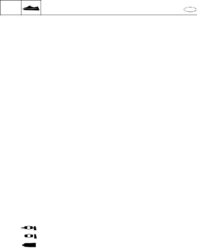
Symbols F to I in an exploded diagram indi- |
|
|
cate the grade of lubricant and the lubrication |
|||
|
|
|
||
|
|
|
point. |
|
|
|
E |
F Apply 4-stroke motor oil |
|
|
|
|
G Apply water resistant grease |
|
G |
H |
|
(Yamaha grease A) |
|
A |
|
|
H Apply ThreeBond 1104J or ThreeBond 1280B |
|
1104J |
1280B |
I Apply molybdenum disulfide grease |
||
|
||||
I |
J |
|
Symbols J to N in an exploded diagram indi- |
|
|
cate the type of sealant or locking agent and |
|||
|
|
|
||
M |
|
GM |
the application point. |
|
|
|
|
J Apply Gasket Maker |
|
K |
L |
|
K Apply LOCTITE 271 (red) |
|
|
L Apply LOCTITE 242 (blue) |
|||
LT |
|
LT |
M Apply LOCTITE 572 |
|
|
N Apply silicone sealant |
|||
|
|
|
||
271 |
|
242 |
|
NOTE:
M |
N |
|
Additional symbols may be used in this man- |
|
|
LT |
|
ual. |
|
|
SS |
|
|
|
|
572 |
|
|
|
|
|
|
|
|
1-2
GEN |
|
|
INFO |
How to use this manual |
E |
Abbreviation
The following abbreviations are used in this service manual.
Abbreviation |
Description |
|
|
API |
American Petroleum Institute |
|
|
APS |
Accelerator position sensor |
|
|
BOW |
Bow end |
|
|
DOWN |
Downside |
|
|
ECM |
Electronic Control Module |
|
|
ETV |
Electronic throttle valve |
|
|
EX |
Exhaust |
|
|
IN |
Intake |
|
|
OL |
Overload |
|
|
OTS |
Off-throttle steering system |
|
|
PORT |
Port side |
|
|
QSTS |
Quick Shift Trim System |
|
|
RPM |
Revolutions Per Minute |
|
|
SAE |
Society of Automotive Engineers |
|
|
STBD |
Starboard side |
|
|
STERN |
Stern end |
|
|
TCI |
Transistor Controlled Ignition |
|
|
TDC |
Top Dead Center |
|
|
TPS |
Throttle Position Sensor |
|
|
UP |
Upside |
|
|
YDIS |
Yamaha Diagnostic System |
|
|
YEMS |
Yamaha Engine Management System |
|
|
Grease table
The following table contains sealants, locking agents, and lubricants used in this service manual that are not listed on the “Symbols” page.
Symbol |
Name |
Application |
||
|
|
|
|
|
|
EP |
|
Epnoc grease AP #0 |
Lubricant |
|
|
|
|
|
|
|
|
Silicone grease |
Water resistant grease |
|
SG |
|||
|
|
|||
|
|
|
|
|
|
1194E |
ThreeBond 1194E |
Sealant |
|
|
|
|
||
|
|
|
|
|
1-3
GEN |
|
|
|
|
|
|
INFO |
|
Safety while working |
E |
|||
|
|
|
Safety while working |
|
|
|
|
|
|
|
|
|
|
|
|
|
To prevent and accident or injury and to |
|||
|
|
|
ensure quality service, follow the safety proce- |
|
||
|
|
1 |
||||
|
|
|
dures provided below. |
|
|
|
|
|
|
Fire prevention |
|
|
|
|
|
|
Gasoline is highly flammable. |
|
||
|
|
|
Keep gasoline and all flammable products |
|
||
|
|
|
||||
|
|
|
away from heat, sparks, and open flames. |
|
|
|
|
|
|
Ventilation |
|
|
|
|
|
|
|
|
|
|
|
|
|
Gasoline vapor and exhaust gas are heavier |
|||
|
|
|
than air and extremely poisonous. If inhaled in |
|||
|
|
|
large quantities, they may cause loss of con- |
|||
|
|
|
sciousness and death within a short time. |
|||
|
|
|
When test running an engine indoors (e.g., in a |
|||
|
|
|
water tank), be sure to do so where adequate |
|||
|
|
|
ventilation can be maintained. |
|
|
|
|
|
|
Self-protection |
|
|
|
|
|
|
Protect your eyes by wearing safety glasses or |
|||
|
|
|
||||
|
|
|
safety goggles during all operation involving |
|||
|
|
|
drilling and grinding, or when using an air com- |
|||
|
|
|
pressor. |
|
|
|
|
|
|
Protect your hands and feet by wearing protec- |
|||
|
|
|
tive gloves and safety shoes when necessary. |
|||
|
|
|
Parts, lubricants, and sealants |
|
|
|
|
|
|
Use only genuine Yamaha parts, lubricants, |
|||
|
|
|
and sealants, or those recommended by |
|||
|
|
|
||||
|
|
|
Yamaha, when servicing or repairing the |
|||
|
|
|
||||
|
|
|
watercraft. |
|
|
|
|
|
|
Under normal conditions, the lubricants men- |
|||
|
|
|
tioned in this manual should not harm or be |
|||
|
|
|
hazardous to your skin. However, you should |
|||
|
|
|
follow these precautions to minimize any risk |
|||
|
|
|
when working with lubricants. |
|
|
|
1.Avoid contact with skin. Do not, for example, place a soiled rag in your pocket.
2.Wash hands and any other part of the body thoroughly with soap and hot water after contact with a lubricant or lubricant soiled clothing has been made.
3.Change and wash clothing as soon as possible if soiled with lubricants.
4.To protect your skin, apply a protective cream to your hands before working on the watercraft.
1-4

GEN INFO
Safety while working |
E |
|
5.Keep a supply of clean, lint-free cloths for wiping up spills, etc.
6.Maintain good standards of personal and industrial hygiene.
Good working practices
Special service tool
Use the recommended special service tools to protect parts from damage. Use the right tool in the right manner; do not improvise.
Tightening torques
Follow the tightening torque specifications provided throughout the manual. When tightening nuts, bolts, and screws, tighten the large sizes first, and tighten fasteners starting in the center and moving outward.
Non-reusable parts
Always use new gaskets, seals, O-rings, cotter pins, circlips, etc., when installing or assembling parts.
Disassembly and assembly
1.Use compressed air to remove dust and dirt during disassembly.
2.Apply oil or fluid to the contact surfaces of moving parts before assembly.
3.Install bearings with the manufacture identification mark in the direction indicated in the installation procedure. In addition, be sure to lubricate the bearings liberally.
4.Apply a thin coat of water resistant grease to the lip and periphery of an oil seal before installation.
5.Check that moving parts operate normally after assembly.
1-5

GEN |
|
|
|
INFO |
Identification number |
E |
|
|
Identification number |
|
|
|
Primary l.D. number |
|
|
|
The primary l.D. number is stamped on a label |
1 |
|
|
attached to the inside of the engine compart- |
||
|
ment. |
|
|
|
Starting primary l.D. number: |
|
|
|
F1W: 800101 |
|
|
|
Engine serial number |
|
|
|
The engine serial number is stamped on a |
|
|
|
label attached to the engine unit. |
|
|
NOTE:
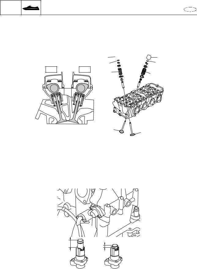
•The label stamped with the engine serial number is located on the cylinder head cover. Remove the engine cover to check the engine serial number.
•Slide the engine cover rearward, and then lift the cover to remove it.
Starting serial number: 6S5: 1000001
Jet pump unit serial number
The jet pump unit serial number is stamped on a label attached to the intermediate housing.
Hull identification number (H.l.N.)
The H.l.N. is stamped on a plate attached to the boarding platform.
1-6
GEN |
|
|
|
|
|
|
INFO |
|
|
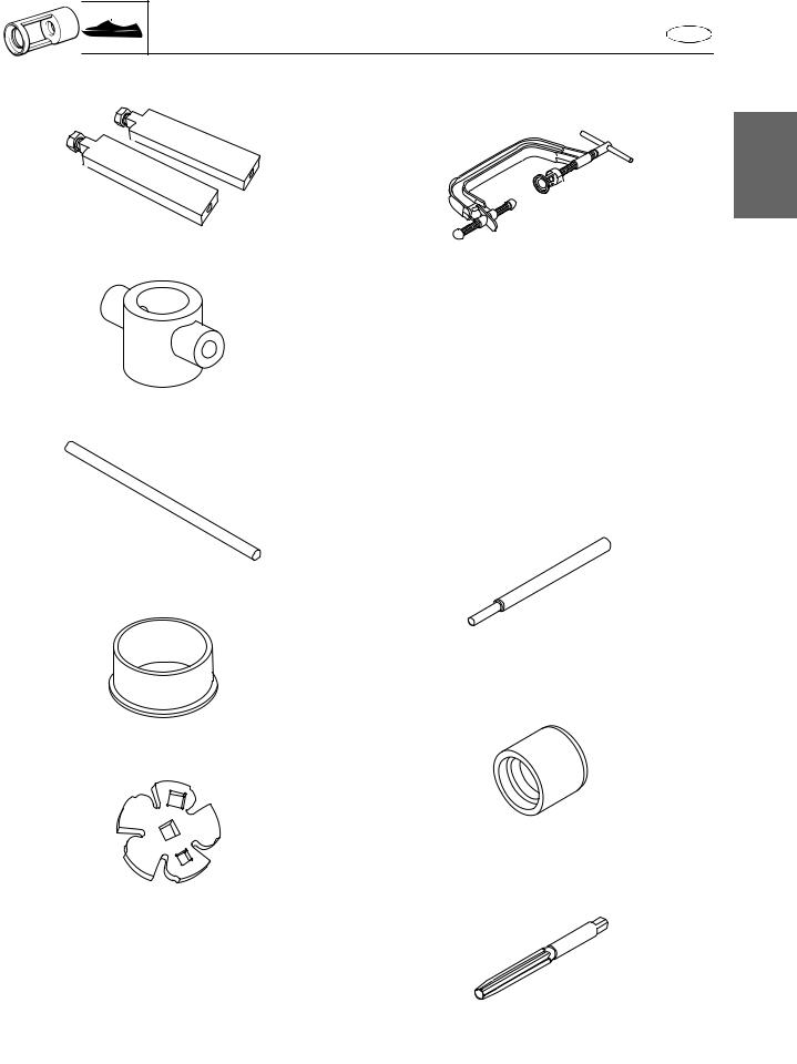
Special service tool |
E |
||
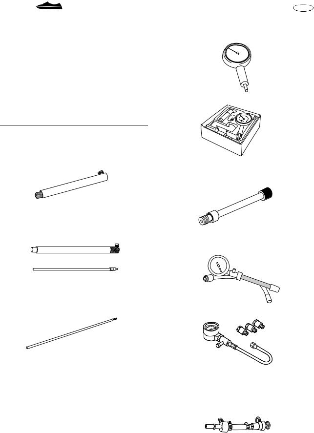
Special service tool |
4 Dial gauge |
|||||
Using the correct special tools recommended |
YU-03097 |
|||||
by Yamaha will aid the work and enable accu- |
|
|||||
rate assembly and tune-up. Improvisations |
|
|||||
and using improper tools can damage the |
|
|||||
equipment. |
|
|
|
|
||
NOTE: |
|
|
|
|
|
|
• For USA and |
Canada, use part numbers |
|
||||
starting with “YB-”, “YM-”, “YU-”, or “YW-.” |
90890-01252 |
|
|
• For other countries, use part numbers start- |
|
ing with “90890-.” |
|
Measuring
1Gauge stand 90890-06725
5 Compression gauge extension
90890-06582
2 Dial gauge stand set (use needle only) YB-06585
6 Compression gauge YU-33223
3 Dial gauge needle
90890-06584
90890-03160
7 Fuel pressure gauge adapter YW-06842
90890-06842
1-7
GEN |
|
|
|
INFO |
|
Special service tool |
E |
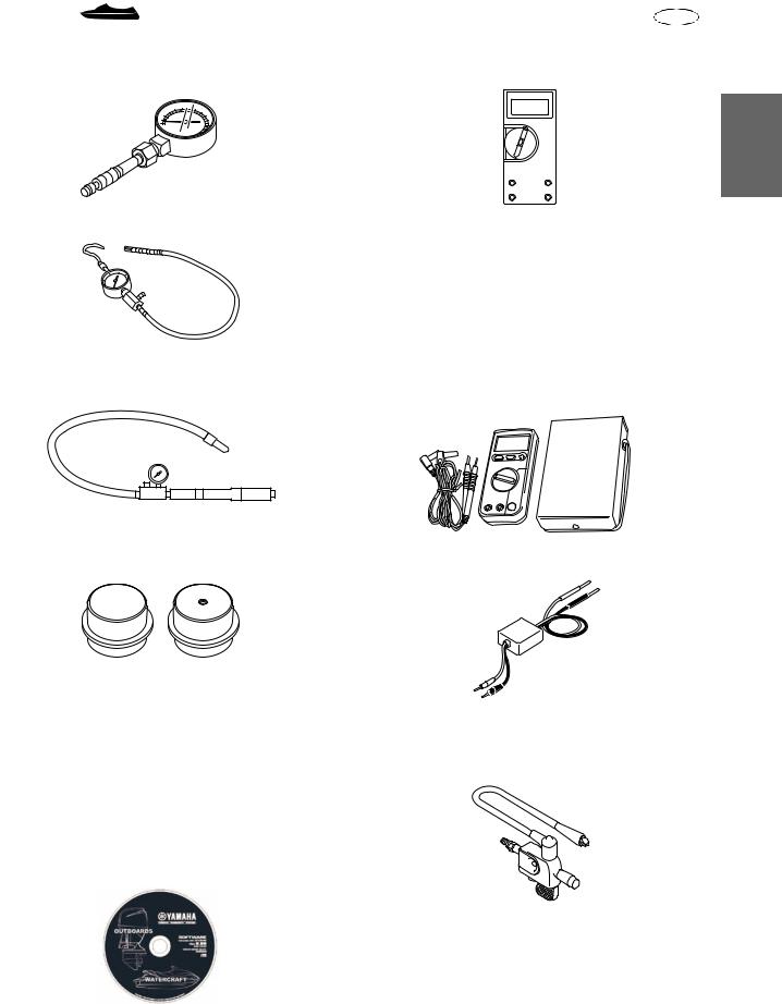
8 Fuel pressure gauge |
C Digital multimeter |
||
YB-06766 |
|
YU-34899-A |
|
1
90890-06786 |
D Peak voltage adapter |
|
YU-39991 |
9 Leakage tester
90890-06840 E Digital circuit tester
90890-03174
0 Air cooler attachment
90890-06731 F Peak voltage adapter B
90890-03172
A YDIS (connecting kit) |
|
60V-85300-04 |
G Spark checker |
|
YM-34487 |
|
Ignition tester |
|
90890-06754 |
B YDIS (CD-ROM, Ver. 1.30)
60V-WS853-04
1-8
GEN |
|
|
|
|
|
|
|
INFO |
|
Special service tool |
E |
||||
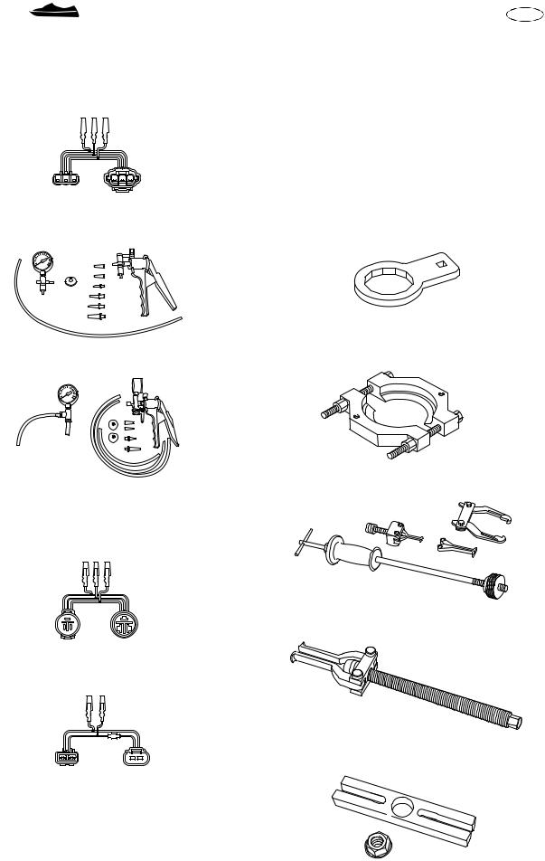
H Test harness (3 pins) |
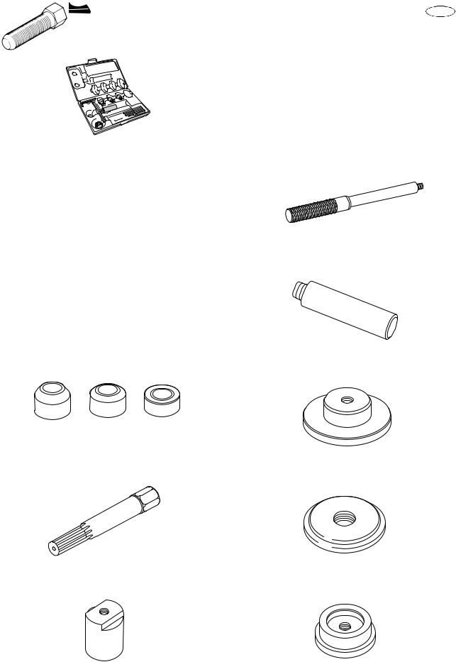
Removal and installation |
||||||
YB-06877 |
|
|
|
|
|
1 Oil filter wrench |
|
Test harness HM090-3 (3 pins) |
90890-06830 |
||||||
90890-06877 |
|
|
|
|
|
|
|
|
|
|
|
|
|
|
|
|
|
|
|
|
|
|
|
2 Exhaust pipe wrench I Lower unit pressure/vacuum tester 90890-06726
YB-35956-A
3 Bearing separator J Vacuum/pressure pump gauge set 90890-06534
90890-06756
K Test harness (3 pins) |
4 Slide hammer and adapters |
YB-06096 |
|
YB-06870 |
|
Test harness SMT250-3 (3 pins) |
|
90890-06870 |
|
5 Bearing puller assembly
90890-06535
L Test harness (2 pins) 90890-06850
6 Stopper guide plate
90890-06501
1-9
GEN |
|
|
INFO |
Special service tool |
E |
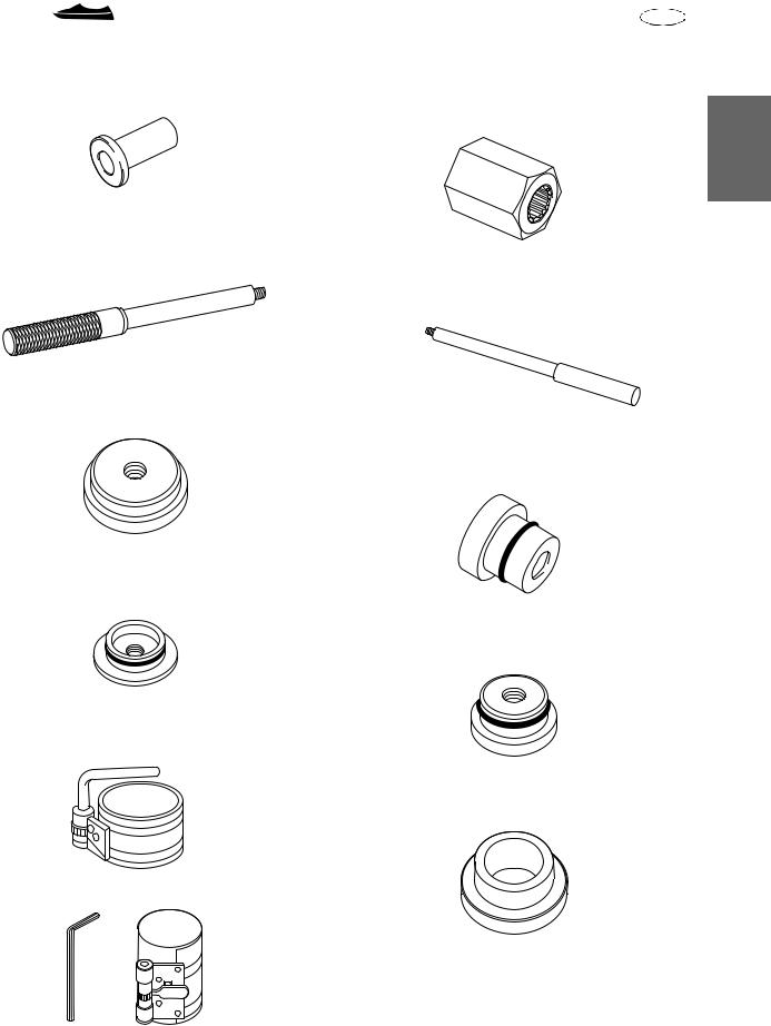
7 Stopper guide stand |
C Valve spring compressor |
|
90890-06538 |
|
YM-04019 |
|
|
90890-04019 |
1
8 Shaft holder |
|
90890-06721 |
D Compressor adapter |
|
YM-04114 |
|
Valve spring compressor attachment |
|
90890-04114 |
9Driver handle 90890-06722
EValve guide remover YB-06801 90890-06801
0Bearing inner race attachment 90890-06661
F Valve guide installer YB-06810 90890-06810
ACoupler wrench 90890-06729
G Valve guide reamer
YM-01196 90890-06804
B Camshaft wrench 90890-06724
1-10
GEN |
|
|
|
INFO |
|
Special service tool |
E |
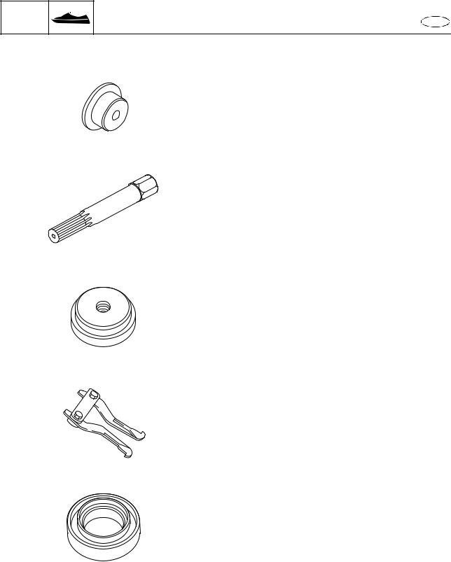
H Neway valve seat kit |
M Rotor puller |
||
YB-91044 |
|
90890-01080 |
|
I Valve seat cutter holder |
N Driver handle (small) |
90890-06812 |
YB-06229 |
J Valve seat cutter |
O Driver rod LS |
Intake |
90890-06606 |
90890-06720 (30°) |
|
90890-06325 (45°) |
|
90890-06324 (60°) |
|
Exhaust |
|
90890-06818 (30°) |
|
90890-06555 (45°) |
|
90890-06323 (60°) |
P Bearing and seal installer |
|
YW-06356 |
KCrankshaft holder YB-06562 90890-06562
QBearing outer race attachment 90890-06623, 90890-06627, 90890-06628
L Flywheel puller |
R Forward bearing race installer |
90890-06723 |
YB-06258 |
1-11
GEN |
|
|
|
INFO |
|
Special service tool |
E |
S Bearing pressure C |
X Drive shaft holder |
||
90890-02393 |
|
YB-06201 |
|
|
|
|
Drive shaft holder 6 |
|
90890-06520 |
1 |
C |
|
|
|
|
TDriver handle (large) YB-06071
YDriver rod L3 90890-06652
UForward gear outer race installer YB-41446
ZDrive shaft needle bearing installer and remover
YB-06194
VBall bearing attachment 90890-06657
[ Needle bearing attachment 90890-06609
W Piston ring compressor
YM-08037
\ Bearing attachment 90890-06728
90890-05158
1-12
GEN INFO
Special service tool |
E |
|
]Bearing cup installer YB-06167
_Shaft holder 90890-06730
aNeedle bearing installer YB-06434
bBearing puller legs YB-06523
cBearing attachment 90890-06727
1-13
GEN INFO
Feature and benefit |
E |
|
Feature and benefit |
|
|
|
|
|
|
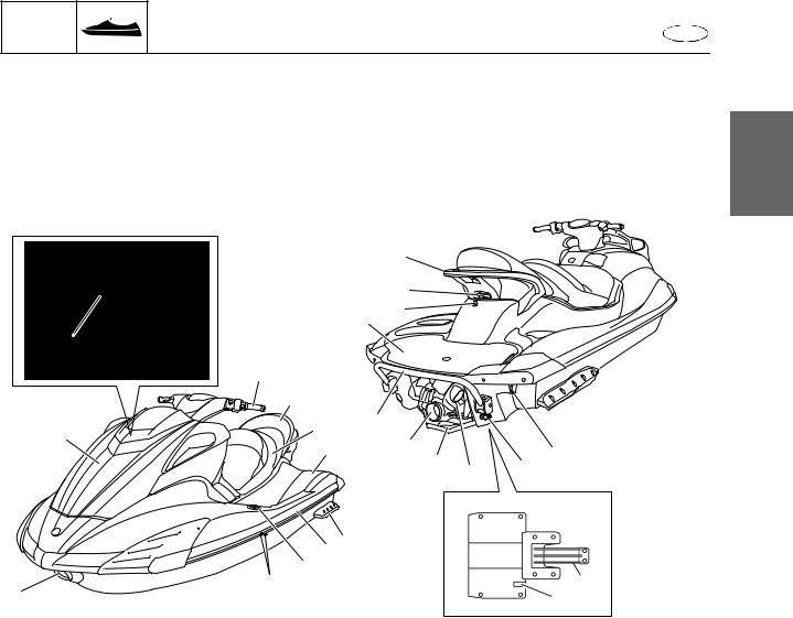
Watercraft overview |
|
|
|
|
|
|
The FX SHO series features a newly designed deck, while keeping the popular hull design of the |
1 |
|||||
FX. Both the deck and hull are made of NanoXcel, which is 25% lighter compared to conventional |
||||||
materials. The fuel filler cap is now located under the hood. |
|
|
||||
|
|
|
||||
|
|
|
M |
|
|
|
|
|
|
L |
|
|
|
|
|
J |
K |
|
|
|
A |
|
|
|
|
|
|
|
1 |
|
|
|
|
|
|
2 |
|
|
|
|
|
|
3 |
I |
|
|
|
|
0 |
|
|
|
|
|
|
4 |
|
H |
|
D |
|
|
|
|
|
|
|||
|
|
G |
|
|
||
|
|
|
F |
E |
|
|
|
|
|
|
|
||
|
|
|
|
|
|
|
|
65 |
|
|
|
|
|
|
7 |
|
|
|
|
|
9 |
8 |
|
|
|
B |
|
|
|
|
|
C |
|
|
|
|
|
|
|
|
|
1 Handlebar |
|
|
H Jet thrust nozzle |
|
|
|
2 Rear seat assembly |
|
|
I Reboarding step assembly |
|
||
3 Front seat assembly |
|
|
J Boarding platform |
|
|
|
4 Foot well |
|
|
K Electric bilge pilot outlet |
|
||
5 Sponson |
|
|
L Ski tow |
|
|
|
6 Gunwale |
|
|
M Hand grip |
|
|
|
7 Pull-up cleat (FX Cruiser SHO) |
|
|
|
|
|
|
8 Cooling water pilot outlet
9 Bow eye
0 Front hood assembly A Fuel filler cap
B Intake grate
C Speed sensor (FX SHO)
Speed and water temperature sensor (FX Cruiser SHO)
D Stern eye E Drain plug
F Reverse gate G Ride plate
1-14
GEN |
|
|
INFO |
Feature and benefit |
E |
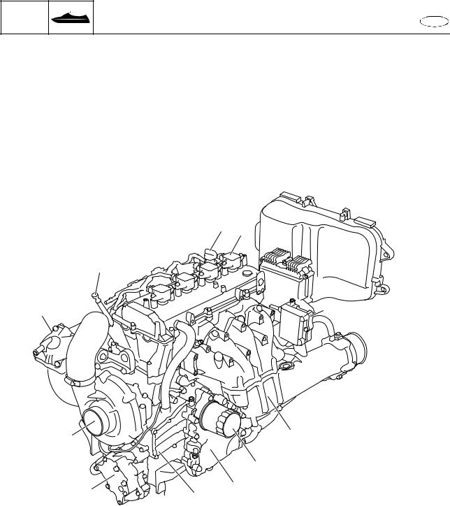
Engine overview
The FX SHO series features a newly designed 1.8 L in-line 4-cylinder supercharged engine. Because of its light and compact design, this engine is roughly the same size as the MR-1 engine used on the FX series watercraft. Both high output and low fuel consumption are achieved using regular unleaded gasoline. The engine meets environmental regulations and complies with the 2006 U.S. EPA (Environmental Protection Agency) emission regulations and the 2008 CARB (California Air Resources Board) 3-star emission regulations.
3 4
2
1
A 
7
0 |
8 |
|
9 |
||
|
1 Air cooler assembly
2 Oil level gauge
3 Oil filler cap
4 Ignition coil
5 Rectifier regulator
6 4 in 1 exhaust system
7 Oil filter
8 Oil cooler assembly
9 Oil separator tank
0 Oil pump assembly
A Supercharger assembly

 5
5
6
1-15
GEN INFO
Feature and benefit |
E |
|
Air filter case and air filter element |
|
|
||
The air filter case and air filter element have been newly designed to handle the increased intake air |
|
|||
volume. The air filter element itself is made of water-repellent material, which prevents water from |
1 |
|||
entering the engine. In addition, the air filter element is secured to the air filter case cover using |
||||
screws. |
|
|
|
|
1 |
|
|
1 Screw |
|
2 |
3 |
2 Air filter element |
|
|
3 Air filter case cover
Supercharger assembly
The supercharger is located on the front of the engine, and is a centrifugal type that rotates the impeller for supercharging. The impeller uses a step-up gear with 2 steps to transmit the rotation of the crankshaft. The impeller rotates about 10 times faster than the crankshaft. The impeller drive gear is equipped with a one-way clutch; therefore, even if the engine stops when the impeller is rotating at high speed, the structure of the impeller allows it alone to continue rotating. The supercharger has excellent durability and is very quiet. In addition, the supercharger is easy to service.
1 |
2 |
DRIVEN GEAR |
|
>>>Number of teeth: |
16 |
IDLE GEAR |
|
>>>Number of teeth |
50 |
BIG: |
|
SMALL: |
19 |
DRIVE GEAR ASSEMBLY
|
>>>Number of teeth: |
60 |
EXAMPLE: |
|
|
Turbine r/min = (60/19) × (50/16) × Engine r/min |
|
|
= 3.16 |
× 3.12 × Engine r/min |
|
= 9.86 |
× Engine r/min |
|
Trolling speed: 9.86 × 1,250 = 12,325 r/min |
3 |
|
1 Impeller
2 Gear
3 One-way clutch
1-16
GEN INFO
Feature and benefit |
E |
|
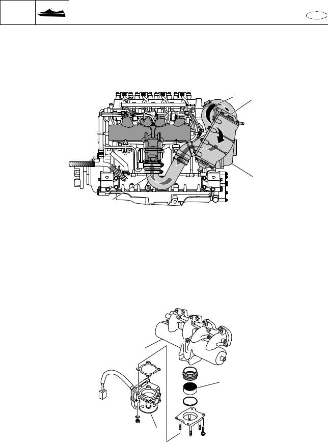
Air cooler assembly
The air cooler assembly uses cooling water to cool the intake air that has been compressed in the supercharger. While the air cooler assembly has an extremely compact design, it functions as a highly efficient heat exchanger to cool the intake air.
È 1
2
|
É |
1 Air cooler assembly |
È Compressed air |
2 Supercharger assembly |
É Cooled air |
Intake system
The intake system has incorporated an electronic control throttle valve (ETV). By using the ETV, the intake system itself is compact and is able to perform various engine controls. Furthermore, the intake air that passes through the ETV is balanced in the intake manifold before it is supplied to each cylinder.
1
2
3
1 Intake manifold
2 Ribbon
3 Throttle body assembly
1-17
GEN INFO
Feature and benefit |
E |
|
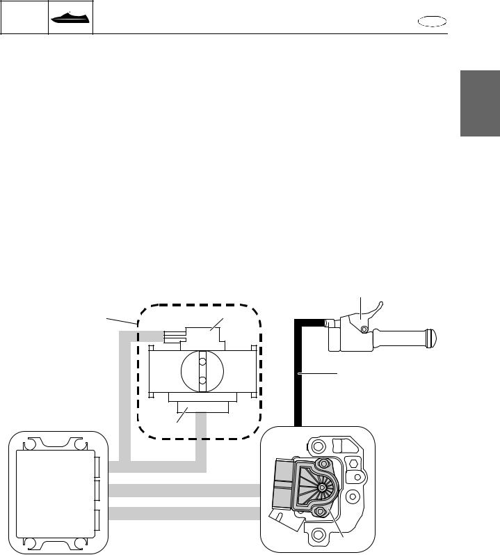
Electronic control throttle valve (ETV) system
The flow chart shows a typical ETV system.
The ETV system consists of a throttle lever, a throttle cable, an accelerator position sensor, electronic control throttle bodies, and an electronic control module (ECM).
A throttle cable connects the throttle lever and the APS. The accelerator position sensor (APS) |
1 |
detects the changes in operation of the throttle lever and changes the output voltage of the APS |
accordingly. This voltage is then transmitted from the APS to the ECM. In accordance with the voltage input from the APS, the ECM operates the DC motor, which is installed on the ETV, and sets the throttle valve to the opening angle that corresponds to the changes in operation of the throttle lever.
At the same time, the throttle position sensor (TPS), which is located on the same axle, detects the changes in the opening angle of the throttle valve and outputs the information to the ECM for optimum operation.
4
1 2
5
3
ECM
6
1 Throttle body assembly
2 TPS
3 DC-motor
4 Throttle lever
5 Throttle cable
6 APS
1-18
GEN INFO
Feature and benefit |
E |
|
Cylinder head assembly
The newly designed cylinder head has 4 valves per cylinder: 2 intake valves and 2 exhaust valves. The shapes of the combustion chamber and piston have been designed to obtain the optimum compression ratio. The valve lifter is a direct-acting type with a valve pad. The valve spring is a single type.
IN |
EX |
1 
 1
1
2 |
2 |
|
|
3 |
3 |
|
|
5 |
4 |
|
|
|
1 Valve lifter |
4 Intake valve |
|
2 Valve pad |
5 Exhaust valve |
|
3 Valve spring |
|
|
Hydraulic timing chain tensioner
A hydraulic timing chain tensioner has been adopted in order to ensure that the tension on timing chain is maintained. When the engine is started and engine oil is supplied to the timing chain tensioner, the structure of the tensioner ensures that the rod is maintained in the proper position.
1
ÈÉ
1 Timing chain tensioner
È Fully extended rod position É Fully retracted rod position
1-19
GEN |
|
|
INFO |
Feature and benefit |
E |
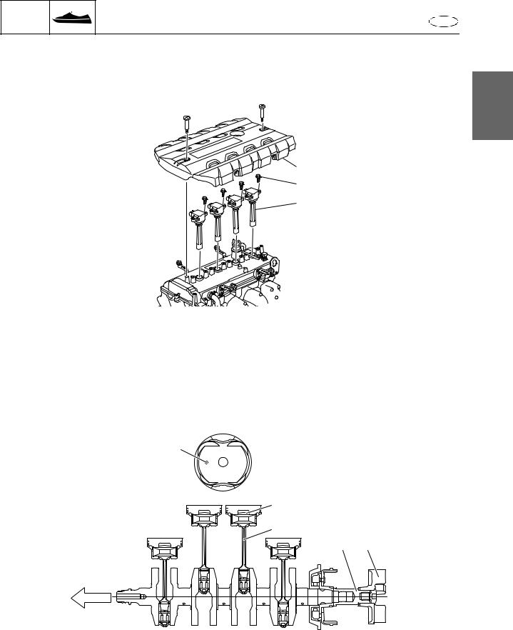
Ignition coil
The ignition coils are a direct-ignition type with a coil installed to each cylinder. The coils are installed to the cylinder head cover using 2 bolts each, which ensures a secure installation and
waterproofing of the spark plug holes.
1
1
2
3
1 Engine cover
2 Bolt
3 Ignition coil
Piston and connecting rod
The pistons and connecting rods have been newly designed. The shape of the piston crown has been designed to achieve the optimum compression ratio and the shape of the connecting rod has been designed to handle the high output. Furthermore, a mark to indicate the installation direction has been placed on the piston crown.
a
1
4
3 2
BOW
1 Piston
2 Drive coupling
3 Transfer shaft
4 Connecting rod
a Piston installation direction mark
1-20
GEN INFO
Feature and benefit |
E |
|
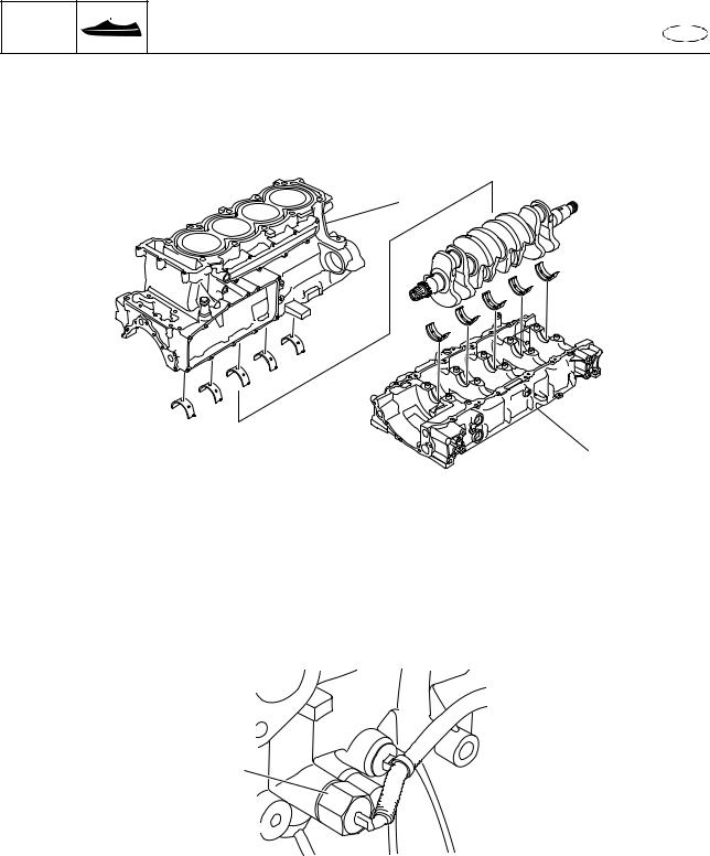
Cylinder block and crankcase
The cylinder block and crankcase have been newly designed. Cast-in iron sleeves, which offer the same high reliability of conventional sleeves, have been adopted. The crankshaft journal portions of the crankcase use a ladder-deck structure in order to achieve high rigidity.
1
2
1 Cylinder block
2 Crankcase
Knock sensor
The knock sensor is installed directly to the cylinder block. The knock sensor detects vibration that is generated by knocking in the combustion chambers and transmits the information to the ECM. If the ECM determines that knocking is occurring, it adjusts the ignition timing to control the knocking and protect the engine from damage.
1
1 Knock sensor
1-21
GEN INFO
Feature and benefit |
E |
|
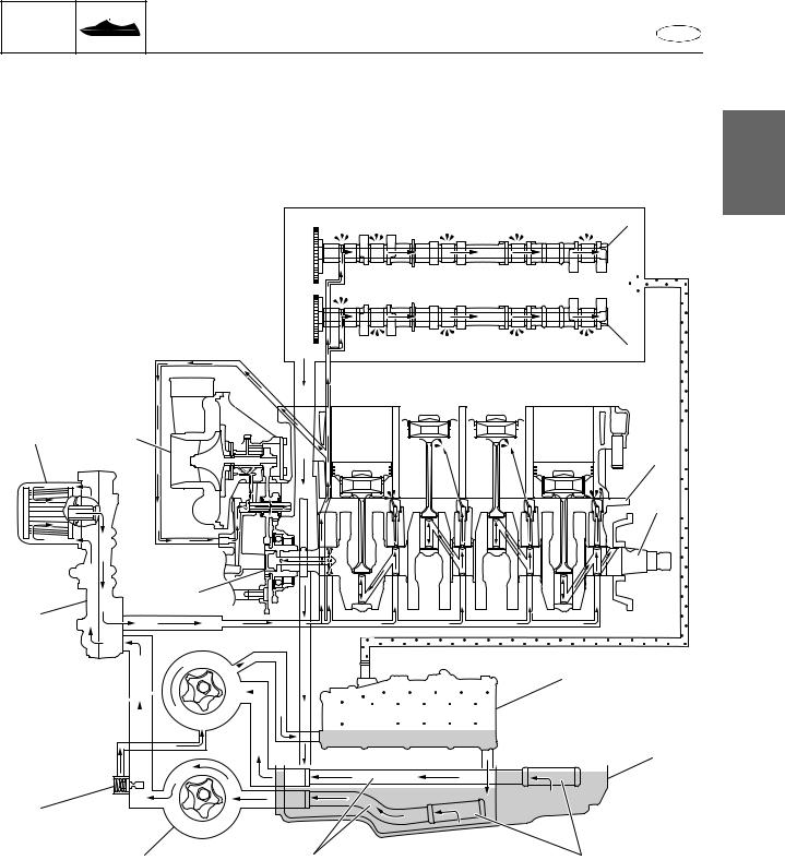
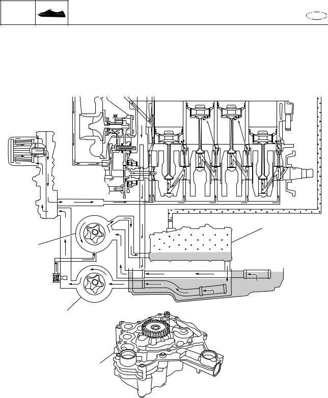
Lubrication system
The FX SHO employs a wet sump lubrication system, which is different from conventional models. There are 2 oil pumps, the scavenge pump and feed pump, located in the oil pan at the bottom of
the engine to drawn in and pressure feed the engine oil.
1
1
2
C E 


 3
3 
4 
D
B


 5 A
5 A


6
0 |
|
|
9 |
8 |
7 |
1 Intake camshaft |
|
0 Relief valve |
2 Exhaust camshaft |
|
A Oil pump assembly (scavenge pump) |
3 Cylinder block |
|
B Oil cooler assembly |
4 Crankshaft |
|
C Oil filter |
5 Oil separator tank |
|
D Drive gear assembly |
6 Oil pan |
|
E Supercharger assembly |
7 Oil strainer |
|
|
8 Oil pipe |
|
|
9 Oil pump assembly (feed pump) |
|
|
1-22
GEN INFO
Feature and benefit |
E |
|
Oil pump assembly
The oil pump assembly is comprised of 2 oil pumps: the scavenge pump and the feed pump. The scavenge pump pressure feeds engine oil from the oil pan to the oil separator tank. The feed pump supplies engine oil from the oil pan to the various engine components.
1
3
2
4
1 Oil separator tank
2 Oil pump assembly (feed pump)
3 Oil pump assembly (scavenge pump)
4 Oil pump assembly
1-23
GEN |
|
|
INFO |
Feature and benefit |
E |
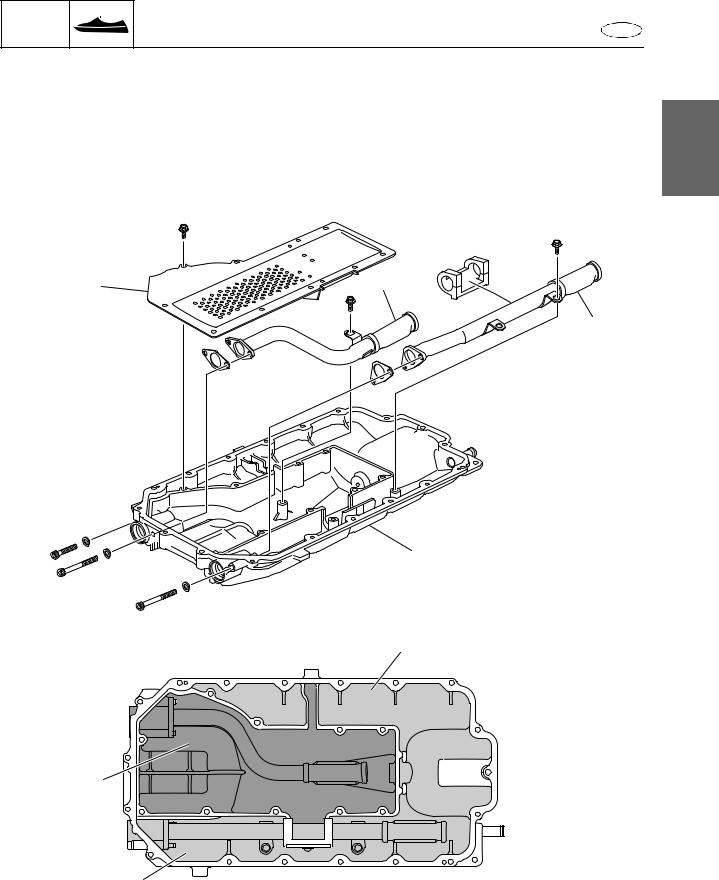
Oil pan
The wet-sump type oil pan is divided into 2 internal compartments. Engine oil in the inner oil pan is pressure-fed to the various engine components by the feed pump. Engine oil in the outer oil pan is sent to the oil separator tank by the scavenge pump, and then it flows into the inner oil pan. By using
2 internal compartments, a stable supply of engine oil is possible even under the harsh operating 1 conditions of watercraft.
1 |
2 |
3
4
|
5 |
È |
|
6 |
|
É |
|
5 |
|
1 Baffle plate |
6 Inner oil pan |
2 Strainer (feed) |
|
3 Strainer (scavenge) |
È To feed pump |
4 Oil pan |
É To scavenge pump |
5 Outer oil pan |
|
1-24
GEN INFO
Feature and benefit |
E |
|
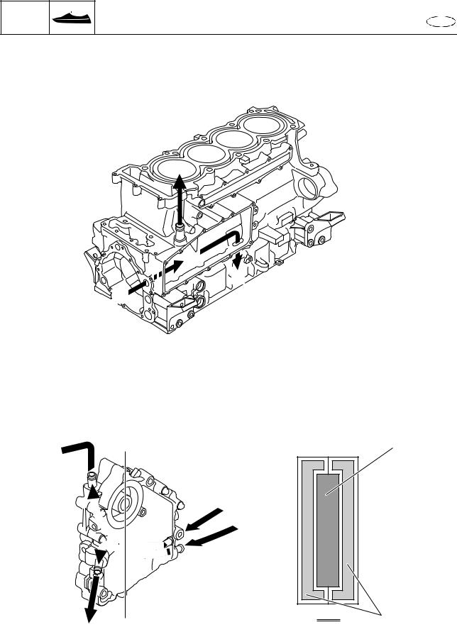
Oil separator tank
The scavenge pump pressure feeds the engine oil to the oil separator tank. The oil saparator tank separates the gas from the engine oil. The gas is routed to the cylinder head cover as blow-by gas and the engine oil flows into the inner oil pan at the center of the oil pan.
É
Ê
È
È From scavenge pump É To cylinder head
Ê To inner oil pan
Oil cooler assembly
The mounting location for the oil filter is integrated into the oil cooler assembly. Cooling water flows on both sides of the engine oil to effectively cool the oil.
É
A |
1 |
È
È
A-A´ 2
A´
É
1 Engine oil
2 Cooling water
È From jet pump unit
É To cooling water pilot outlet on port side
1-25
Loading...