


DUAL BAND FM TRANSCEIVER
FTM-350 SERIES
OPERATING MANUAL
VERTEX STANDARD CO., LTD.
4-8-8 Nakameguro, Meguro-Ku, Tokyo 153-8644, Japan
VERTEX STANDARD
US Headquarters
10900 Walker Street, Cypress, CA 90630, U.S.A.
YAESU UK LTD.
Unit 12, Sun Valley Business Park, Winnall Close
Winchester, Hampshire, SO23 0LB, U.K.
VERTEX STANDARD HK LTD.
Unit 5, 20/F., Seaview Centre, 139-141 Hoi Bun Road,
Kwun Tong, Kowloon, Hong Kong
VERTEX STANDARD (AUSTRALIA) PTY., LTD.
Normanby Business Park, Unit 14/45 Normanby Road Notting Hill 3168, Victoria, Australia

Contents
Front Panel Controls & Switches .......................... |
1 |
Timer Page Operation ............................................ |
2 |
Radio Page Basic Operation .................................. |
3 |
[SMART FUNCTION] Key ................................... |
4 |
General ................................................................. |
4 |
[SMART FUNCTION] Key Command Details ... |
5 |
Memory Operation ................................................. |
6 |
Memory Storage ................................................... |
6 |
Storing Independent Transmit Frequency ............ |
7 |
Memory Recall ..................................................... |
8 |
Memory Edit ........................................................ |
9 |
Labeling Memories .......................................... |
9 |
Copying Memories ........................................... |
9 |
Deleting Memories ........................................... |
9 |
Memory Channel Sort ........................................ |
10 |
AF Dual Operation ............................................... |
11 |
Band Scope Operation ......................................... |
12 |
General ............................................................... |
12 |
Enhanced Mode .................................................. |
13 |
CTCSS/DCS/EPCS Operation ............................ |
14 |
CTCSS Operation ............................................... |
14 |
DCS Operation ................................................... |
14 |
EPCS Operation ................................................. |
15 |
Scan Operation ..................................................... |
16 |
VFO Scan ........................................................... |
16 |
Memory Scan ..................................................... |
16 |
Programmable Memory Scan (PMS) ................. |
17 |
Priority Channel Scan (Dual Watch) .................. |
17 |
Bluetooth® Operation ......................................... |
18 |
Pairing ................................................................ |
18 |
Operation ............................................................ |
19 |
Internet Connection Feature ............................... |
20 |
SRG (“Sister Radio Group”) Mode .................... |
22 |
FRG (“Friendly Radio Group”) Mode ............... |
21 |
DTMF Operation .................................................. |
22 |
Manual DTMF Tone Generation........................ |
22 |
DTMF Autodialer ............................................... |
22 |
Baro/Alti Page Operation .................................... |
23 |
GPS Operation ...................................................... |
24 |
Navi Operation ..................................................... |
28 |
Audio Playback Operation .................................. |
30 |
Miscellaneous Setting (Set Mode Operation) ..... |
32 |
AUDIO Group .................................................... |
33 |
TX/RX Group ..................................................... |
35 |
DISPLAY Group ................................................ |
37 |
MEMORY Group ............................................... |
38 |
SCAN Group ...................................................... |
39 |
SYSTEM Group ................................................. |
40 |
NAVI Group ....................................................... |
43 |
TIMER/CLOCK Group...................................... |
44 |
SIGNALING Group ........................................... |
45 |
OPTION Group .................................................. |
47 |
Cloning .................................................................. |
49 |
Installation ............................................................ |
50 |
Preliminary Inspection ....................................... |
50 |
Installation Tips .................................................. |
50 |
Safety Information .............................................. |
51 |
Special Function Menu ........................................ |
52 |
Accessories & Options .......................................... |
53 |
Supplied Accessories ......................................... |
53 |
Optional Accessories .......................................... |
53 |
Specification .......................................................... |
54 |
FCC Notice ............................................................ |
56 |
RESET PROCEDURE
When key functions are lost, or erratic operation is encountered, you may clear all settings of the transceiver and set them to the factory default with the following procedures:
1.Turn the radio “off”.
2.Press and hold in the key located to the left of the [POWER] switch while turning the radio on, to enter the “Special Function” mode.
3.Rotate the left side [DIAL] knob to select “6 ALL RESET”.
4.Press the left side [DIAL] knob and confirm that (OK? [SET]) is displayed on the LCD.
5.Press the left side [DIAL] knob once more to complete the reset procedure.
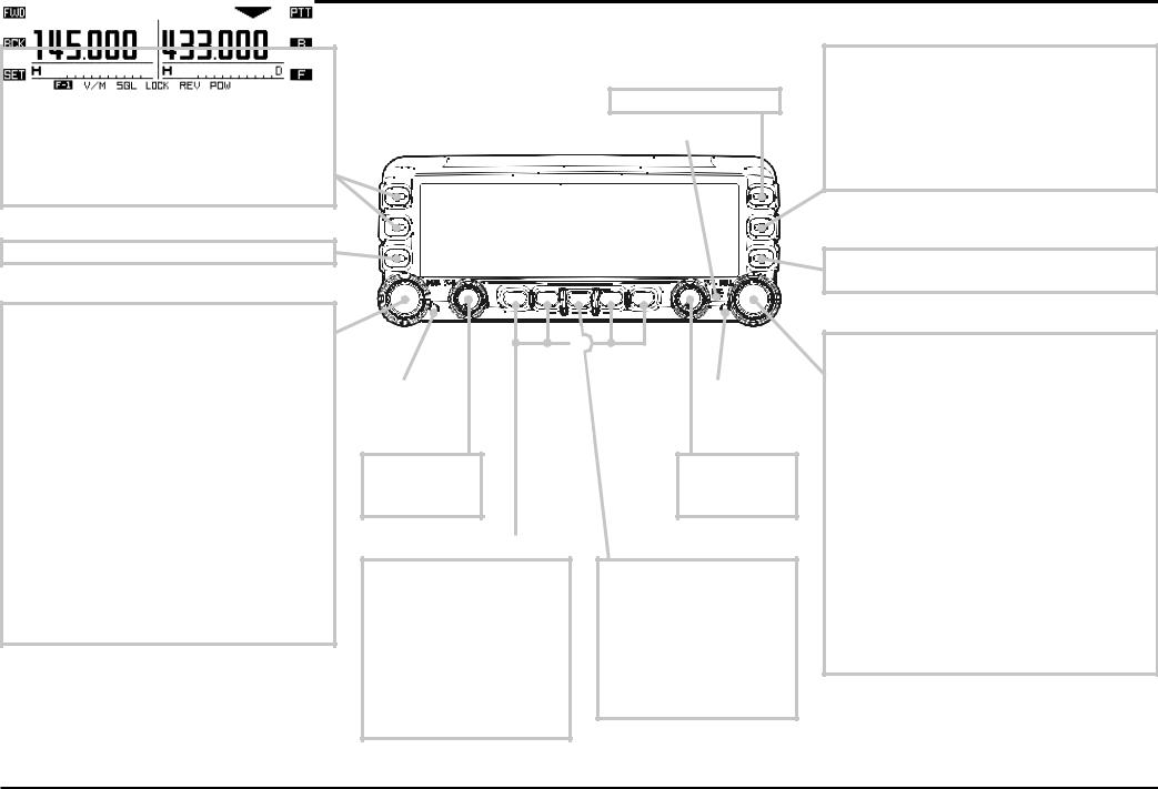
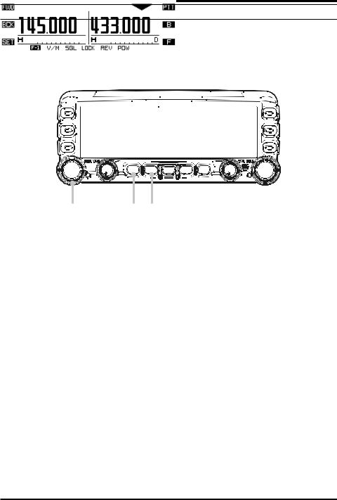
FRONT PANEL CONTROLS & SWITCHES
[FWD]/[BCK](PAGE) KEY
Press these keys briefly to select the operating function pages.
The available pages are: “Radio” page, “Timer” page, “Baro/Alti” page, “Navigation” page , and “GPS Status” page .
: Requires optional “FGPS-1” GPS Unit.
Press and hold in these keys to toggle the Dual Receive feature “on” and “off”.
[SET](SET MODE) KEY
Press this key to access the Set Mode.
[DIAL] KNOB
Rotate this knob to select the operating frequency (or memory channel) of the left side receiver.
Press and hold this knob for one second to enable tuning of the VFO frequency in 1 MHz step.
When the left side receiver is set to “Main” band, press this knob briefly to activate the Band Scope feature.
When the leftside receiver is set to “Sub” band, press this knob briefly to change the left side receiver to “Main” band.
While using “Mono” band operating mode:
When the left side receiver is set to “Main” band, press this knob briefly to activate the Band Scope feature.
When the left side receiver is set to “Sub” band, press and hold this knob to toggle “Sub” band operation “on” and “off”.
[PTT] KEY
Press this key to transmit.
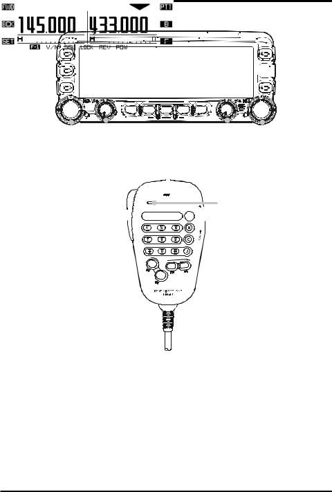
MICROPHONE
DIAL
ILLUMINATION
[VOL] KNOB
Adjusts the left side receiver’s audio volume.
DIAL
ILLUMINATION
[VOL] KNOB
Adjusts the right side receiver’s audio volume.
[SMART FUNCTION] KEY |
[POWER] SWICTH |
These four keys select many of the most important operating features of the transceiver.
When changing the operating function page or pressing the [FUNCTION] key, the current function of these keys will change and the function will appear above each key.
Press and hold this key for two seconds to toggle the transceiver’s power on and off.
Press this key briefly while the transceiver is turned on to toggle the key lockout feature on or off.
[B](BAND) KEY
Press this key to change the Main operating band. Available bands are:
Left Band: AM Radio, FM Radio, 144 MHz Band, 430 MHz Band, and Audio Line-In
Right Band: 144 MHz Band and 430 MHz Band You may recall additional operating bands via Set Mode item “B05: RX EXPANSION”. See page 35.
[F](FUNCTION) KEY
Press this key to change the current functions of the [SMART FUNCTION] keys.
[DIAL] KNOB
Rotate this knob to select the operating frequency (or memory channel) of the right side receiver.
Press and hold this knob for one second to enable tuning of the VFO frequency in 1 MHz step.
When the right side receiver is set to “Main” band, press this knob briefly to activates the Band Scope feature.
When the right side receiver is set to “Sub” band, press this knob briefly to change the right side receiver to “Main” band.
While using “Mono” band operating mode:
When the right side receiver is set to “Main” band, press this knob briefly to activate the Band Scope feature.
When the right side receiver is set to “Sub” band, press and hold this knob to toggle “Sub” band operation “on” and “off”.
FTM-350 SERIES OPERATING MANUAL |
1 |

TIMER PAGE OPERATION
“CLOCK” |
|
“COUNT UP” TIMER |
|
“COUNT DOWN” TIMER |
|
|
|
|
|
1 |
2 |
1Press the [FWD] or [BCK] key repeatedly, until the “Timer Page” appears.
2Press the [MODE] key repeatedly, until the “Clock” appears.
To return to the “Radio” page, press the [FWD] or [BCK] key repeatedly, until the “Radio” Page appears.
The transceiver’s clock is setup from the Set mode item “I01 DATA&TIME ADJUST” in the “TIMER/CLOCK” group. See page 44 for details.
1 |
24 |
35 |
|
6 |
|
1Press the [FWD] or [BCK] key repeatedly, until the “Timer Page” appears.
2 Press the [MODE] key repeatedly, until the “Count Up” timer appears.
The “Count Up” timer has two modes: with Lap function and without Lap function.
3Press the [SETUP] key to set the interval time of the timer beep: rotate the [DIAL] knob to select the interval time, then press the [SETUP] key.
4 Press the [START] key to initiate the “Count Up” timer.
5Press the [LAP] key to save the lap time, if desired (up to four laps).
6 Press the [STOP] key to stop the “Count Up” timer.
7Press and hold the [START] key for two seconds to reset the “Count Up” timer.
When the optional GPS antenna is connected, the average speed, or the maximum speed of your vehicle may be displayed instead of the lap function, by pressing the [MODE] key again. Press the [DISP] key to switch between average and maximum speed.
To return to the “Radio” page, press the [FWD] or [BCK] key repeatedly, until the “Radio” Page appears.
1 |
24 |
35 |
|
6 |
|
|
7 |
|
1Press the [FWD] or [BCK] key repeatedly, until the “Timer Page” appears.
2 Press the [MODE] key repeatedly, until the “Count Down” timer appears.
The “Count Down” timer has two modes: with Lap function and without Lap function.
3Press the [SETUP] key to set the setup time: rotate the [DIAL] knob to select the setup time, then press the [SETUP] key.
4 Press the [START] key to initiate the “Count Down” timer.
5 Press the [LAP] key to save the lap time, if desired (up to four laps).
6 Press the [STOP] key to stop the “Count Down” timer.
7Press and hold the [START] key for two seconds to reset the “Count Down” timer.
When the optional GPS antenna is connected, the average speed, or the maximum speed of your vehicle may be displayed instead of the lap function, by pressing the [MODE] key again. Press the [DISP] key to switch between average and maximum speed.
To return to the “Radio” page, press the [FWD] or [BCK] key repeatedly, until the “Radio” Page appears.
2 |
FTM-350 SERIES OPERATING MANUAL |
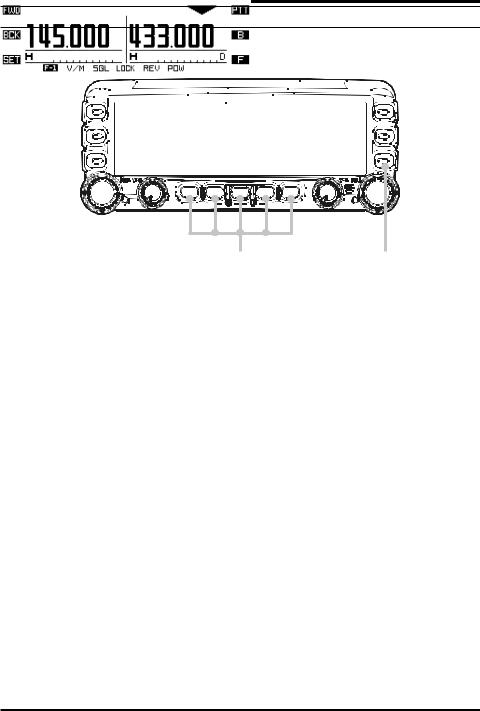
RADIO PAGE BASIC OPERATION
The basic operations are listed numerically in the illustration below.


 5
5
|
|
|
|
|
|
|
|
|
|
|
|
|
|
|
|
|
|
|
|
|
|
|
|
|
|
6 |
2 |
|
31 |
2 |
4 |
|||||||
|
|
|
|
8 |
|
|
6 |
|||||
|
|
|
|
|
|
|
|
|
|
|
|
|
MICROPHONE
7


1 Press and hold the [POWER] key for two seconds to turn the transceiver on. 2 Rotate the [VOL] knob to adjust the audio volume level.
3Press the [SQL] key briefly then rotate the [DIAL] knob carefully to adjust the squelch threshold level.
4
5 Press the [B] key to select the operating band of the “Main” band. 6 Rotate the [DIAL] knob to select the operating frequency.
7 Press and hold the [PTT] key, and speak into the microphone in a normal voice level.
8
FTM-350 SERIES OPERATING MANUAL |
3 |
[SMART FUNCTION] KEY
GENERAL
The FTM-350 Series Transceiver operations are performed using the [SMART FUNCTION] keys. The various functions of the keys are changed by pressing the [F] key.
[SMART FUNCTION] key [FUNCTION] key
Pressing the [F] key repeatedly will change the function command of each [SMART FUNCTION] key as shown in the following tables. It is easy to recall and perform a desired operation. The current function of each key is shown in the display above the key button.
Default
F-1 |
V/M |
SQL |
LOCK |
REV |
POW |
F-2 |
SCAN |
DW |
LOCK |
SKIP 1 |
AD-F 2 |
When the optional Voice Guide Unit is installed.
F-1 |
V/M |
SQL |
LOCK |
REV |
POW |
F-2 |
SCAN |
DW |
LOCK |
SKIP 1 |
AF-D 2 |
F-3 |
REC |
X CLR |
LOCK |
PLAY |
VOICE |
When the optional Voice Guide Unit is installed and the APRS feature is activated.
|
F-1 |
V/M |
SQL |
LOCK |
|
REV |
POW |
|
F-2 |
SCAN |
DW |
LOCK |
|
SKIP 1 |
AF-D 2 |
|
F-3 |
S LIST |
MSG |
LOCK |
|
BCON |
B-TX |
|
F-4 |
REC |
X CLR |
LOCK |
|
PLAY |
VOICE |
Press and hold the [F] key for two seconds. |
|
|
|||||
|
|
|
|
|
|
|
|
|
SQL |
TYPE |
T FRQ |
LOCK |
|
D COD |
P FRQ |
1: The [SKIP] command appears only in memory mode.
2: You may change the [AD-F] command to another command with Set Mode item “G05 F KEY”. See page 40.
4 |
FTM-350 SERIES OPERATING MANUAL |

[SMART FUNCTION] KEY
[SMART FUNCTION] KEY COMMAND DETAILS
|
V/M |
Press Key |
Switches frequency control between the “VFO” and “Memory System”. |
|
|
Press & Hold Key |
Activates the “Memory Write” mode (for memory channel storage). |
||
|
|
|||
|
SQL |
Press Key |
Activates the Squelch threshold level. |
|
|
Press & Hold Key |
No Action. |
||
|
|
|||
F-1 |
LOCK |
Press Key |
Toggles the key lockout feature “on and “off”. |
|
Press & Hold Key |
Toggles the transceiver power “on and “off”. |
|||
|
|
|||
|
REV |
Press Key |
Reverses transmit and receive frequencies while working through a repeater. |
|
|
Press & Hold Key |
No Action. |
||
|
|
|||
|
POW |
Press Key |
Selects the desired transmit power output level (“LOW”, “MID”, and “HIGH”) |
|
|
Press & Hold Key |
No Action |
||
|
|
|||
|
|
|
|
|
|
SCAN |
Press Key |
Activates the Scanner. |
|
|
Press & Hold Key |
No Action. |
||
|
|
|||
|
DW |
Press Key |
Activates the Dual Watch feature. |
|
|
Press & Hold Key |
No Action. |
||
|
|
|||
F-2 |
LOCK |
Press Key |
Toggles the key lockout feature “on and “off”. |
|
Press & Hold Key |
Toggles the transceiver power “on and “off”. |
|||
|
|
|||
|
SKIP |
Press Key |
Selects the “scan flag” to the current memory channel. |
|
|
Press & Hold Key |
No Action. |
||
|
|
|||
|
AD-F |
Press Key |
Activates the AF Dual function. |
|
|
Press & Hold Key |
No Action. |
||
|
|
|||
|
|
|
|
|
|
S LIST |
Press Key |
Opens the “Station List” window. |
|
|
Press & Hold Key |
No Action. |
||
|
|
|||
|
MSG |
Press Key |
Opens the “Message List” window. |
|
|
Press & Hold Key |
No Action. |
||
|
|
|||
F-3 |
LOCK |
Press Key |
Toggles the key lockout feature “on and “off”. |
|
Press & Hold Key |
Toggles the transceiver power “on and “off”. |
|||
|
|
|||
|
BCON |
Press Key |
Changes the APRS beacon: ON, OFF or AUTO. |
|
|
Press & Hold Key |
No Action. |
||
|
|
|||
|
B-TX |
Press Key |
Transmits the APRS beacon. |
|
|
Press & Hold Key |
No Action. |
||
|
|
|||
|
|
|
|
|
|
REC |
Press Key |
Initiates the recording of the incoming receiver audio. |
|
|
Press & Hold Key |
No Action. |
||
|
|
|||
|
X CLR |
Press Key |
Clears the recording data. |
|
|
Press & Hold Key |
No Action. |
||
|
|
|||
F-4 |
LOCK |
Press Key |
Toggles the key lockout feature “on and “off”. |
|
Press & Hold Key |
Toggles the transceiver power “on and “off”. |
|||
|
|
|||
|
PLAY |
Press Key |
Plays back the recorded data. |
|
|
Press & Hold Key |
Selects the Voice Memory Register (slot 1 - 8, or ALL). |
||
|
|
|||
|
VOICE |
Press Key |
Announces the operating frequency of the “Main” band. |
|
|
Press & Hold Key |
No Action. |
||
|
|
|||
|
|
|
|
|
|
TYPE |
Press Key |
Selects the Squelch type. |
|
|
Press & Hold Key |
No Action. |
||
|
|
|||
|
T FRQ |
Press Key |
Selects the CTCSS Tone frequency. |
|
|
Press & Hold Key |
No Action. |
||
|
|
|||
SQL |
LOCK |
Press Key |
Toggles the key lockout feature “on and “off”. |
|
Press & Hold Key |
Toggles the transceiver power “on and “off”. |
|||
|
|
|||
|
D COD |
Press Key |
Selects the DCS code. |
|
|
Press & Hold Key |
No Action. |
||
|
|
|||
|
P FRQ |
Press Key |
Selects the User Programmed Reverse CTCSS Tone frequency.. |
|
|
Press & Hold Key |
No Action. |
||
|
|
FTM-350 SERIES OPERATING MANUAL |
5 |
MEMORY OPERATION
MEMORY STORAGE
Before beginning the Memory Storage operation, select the desired frequency while operating in the “Main” band VFO. Be sure to set up any desired CTCSS or DCS tones, as well as any repeater offset. The power level setting is also stored in the memory.
2 12 22
2
3
1 Press and hold in the [V/M] key for two seconds to display the “Memory Edit” window.
2If you wish to append an Alpha/numeric “Tag” to this channel, press and hold the [V/M] key again. Then enter the desired name “Tag” (up to 8 characters) one of the methods shown in the following examples. Otherwise, skip to the next step.
Example 1: Enter the characters/numbers by pressing the microphone keypad buttons; or use the microphone [UP]/[DWN] keys to select them. Press the [B] key to move the cursor to the next digit. Press the [A] key to backspace the cursor, and press the [C] key to delete all data after the cursor. You may change the character (uppercase, lowercase, numeric, or symbol) by pressing the [ ] key.
Example 2: Rotate the left side [DIAL] knob to select a character/number and press the [ ] key to move the cursor to the next digit. Press the [BS] key to backspace the cursor. You may change the character (capital, small, nu-
meric, or symbol) by pressing the [FONT] key.
3 Press the [V/M] key to store the frequency and settings into memory.
Impotant Note
On rare occasions the stored data may become corrupted by miss operation, or static electricity. When repairs are made, the memory data may be lost. Please write down or record the memory information so you will be able to restore it if needed.
6 |
FTM-350 SERIES OPERATING MANUAL |
MEMORY OPERATION
STORING INDEPENDENT TRANSMIT FREQUENCY (“ODD SPLIT”)
All memories can store an independent transmit frequency, for operation on repeaters with non-standard shift.
To store the “Odd Split” transmit frequency, first store the receive frequency using the method already described on the previous page. Then follow the below procedures:
213
1 Tune the desired transmit frequency on the “Main” band, then press and hold in the [V/M] key for two seconds.
2Rotate the left side [DIAL] knob to select the same memory channel number as used in step 1 above.
3 Press the [TXIN] key to store the independent transmit frequency into memory.
FTM-350 SERIES OPERATING MANUAL |
7 |

MEMORY OPERATION
MEMORY RECALL
|
|
|
|
|
|
|
|
|
|
|
|
|
|
|
|
|
|
|
|
|
|
|
|
|
|
|
|
|
|
|
|
|
|
|
|
|
|
|
|
|
|
|
|
|
|
|
|
|
|
|
|
|
|
|
|
|
|
|
|
|
|
|
|
|
|
|
|
|
|
|
|
|
|
|
|
|
|
|
|
|
|
|
|
|
|
|
|
|
|
|
|
|
|
|
|
|
|
|
|
|
|
|
|
|
|
|
|
|
|
|
|
|
|
|
|
|
|
|
|
|
|
|
|
|
|
|
|
|
|
|
|
|
|
|
|
|
|
|
|
|
|
|
|
|
|
|
|
|
|
|
|
|
|
|
|
|
|
|
|
|
|
|
|
|
|
|
|
|
|
|
|
|
|
|
|
|
|
|
|
|
|
|
|
|
|
|
|
|
|||
1 |
|
|
|
|
|
|
|
|
2 |
||||||
3 |
|
|
|
|
|
|
|
|
|
|
|
|
|
|
|
1 Press the [V/M] key, to set the “Main” band to the memory mode. 2 Rotate the [DIAL] knob to select the desired memory channel. 3 To return to the VFO mode, press the [V/M] key.
When the radio is in the memory mode, you may recall a memory to the main memory display by entering the memory number using the microphone keypad.
For example, to recall memory channel #14, press [0] [1] [4].
When an “Odd Split” memory channel is recalled, the “ 

 ” indication will appear in the display.
When a “Tagged” memory channel is displayed with the Alpha/numeric “Tag”, a small frequency indication will also be shown. You may change the display between “Tag” indication and “Frequency” indication via Set Mode item “D01 MEMORY DISPLAY” in the “MEMORY” group.
8 |
FTM-350 SERIES OPERATING MANUAL |
MEMORY OPERATION
MEMORY EDIT
The memory channels may be edited using Set Mode item “D02 MEMORY EDIT” in the “MEMORY” group.
LABELING MEMORIES
1.Rotate the left side [DIAL] knob to select a memory channel to append or change the label.
2.Press the [V/M] key for two seconds, and then add or change the label in the same manner as step 2 of the “Memory Storage” procedure (see page 6).
COPYING MEMORIES
1.Rotate the left side [DIAL] knob to select the memory channel to be copied.
2.Press the [SEL] key. The selected column will blink.
3.Rotate the left side [DIAL] knob to select a memory channel to store the data.
4.Press the [CPY] key to copy the memory channel data.
5.Press the [SEL] key to save the data and stop the column blinking.
DELETING MEMORIES
1.Rotate the left side [DIAL] knob to select the memory channel to delete.
2.Press the [SEL] key. The selected column will blink.
3.Press the [DEL] key to delete the memory channel data.
FTM-350 SERIES OPERATING MANUAL |
9 |

MEMORY OPERATION
MEMORY CHANNEL SORT
The memory channels may be sorted and renumbered by frequency, from low to high using the “Special Function” mode.
1.Turn the radio off.
2.To enter the “Special Function” mode, turn the radio on while pressing and holding the key located at the left of the [POWER] switch.
3.To sort the memory channels in the left band, rotate the left side [DIAL] knob to select function menu item “3 L-MEMORY SORT”. To sort the memory channels in the right band, rotate the left side [DIAL] knob to select function menu item “4 R- MEMORY SORT”.
4.Press the left side [DIAL] knob, to display the confirmation message “OK? [SET]” on the display. If you decide to cancel the memory channel sort, press the [ESC] key.
5.Press the left side [DIAL] knob again. After several seconds, sorting is complete, and the transceiver will reset automatically.
10 |
FTM-350 SERIES OPERATING MANUAL |
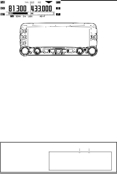
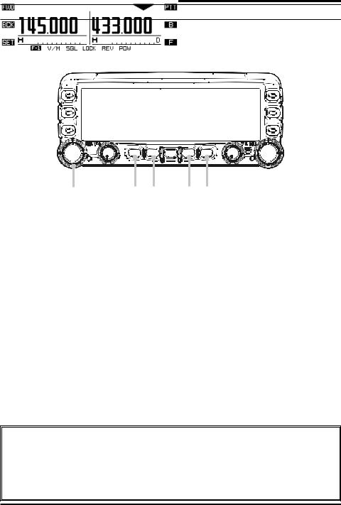
AF DUAL OPERATION
The AF Dual function permits monitoring an amateur band frequency while listening to an FM broadcast station.
Important Note: The AF Dual function will not activate while the radio is in “Mono” band mode.


 6
6


 1
1
|
|
|
|
|
|
|
|
|
|
3 |
2 |
|||
|
|
4 |
||
|
|
7 |
||
1 Press the [F] key repeatedly, until the [SMART FUNCTION] keys change to the “F-2” mode.
2 Press the [AD-F] key to activate the AF Dual function.
The left side receiver switches to FM Broadcast. The right side receiver will monitor the amateur frequencies, while you listen to the FM Broadcast station.
3 Rotate the left side [DIAL] knob to tune the desired FM broadcast stations.
4To change the audio source to the AM Broadcast band, or Line-In audio, press and hold the [AD-F] key for two seconds to access the Set Mode. Select the desired audio source by rotating the left side [DIAL] knob, and then press the [ESC] key.
5When a signal is received in the amateur band, the amateur band audio is output to the speaker. The FM or AM broadcast station will no longer be heard.
6 When the right side receiver is set in the amateur band by “Main” band, you may transmit on the amateur band by pressing the [PTT] key.
7 Press the [AD-F] key to disable the AF Dual function and return to normal operation.
When operating with APRS or Packet on the left side band, the operating frequency and baud rate of the APRS or Packet operation will appear on the display.
Operating Frequency Baud Rate
FTM-350 SERIES OPERATING MANUAL |
11 |

BAND SCOPE OPERATION
GENERAL
The Band Scope permits viewing operating activity on channels above and below the current operating channel, in the VFO mode.
Important Note: The Band Scope feature will not activate while the radio is in Dual Band receive with the “Mono” band mode.
|
|
|
|
|
|
|
|
|
|
|
|
|
|
|
|
|
|
|
|
|
|
|
|
|
|
|
|
|
|
|
|
|
|
|
|
|
|
|
|
|
|
|
|
|
|
|
|
|
|
|
|
|
|
|
|
|
|
|
|
|
|
|
|
|
|
|
|
|
|
|
|
|
|
|
|
|
|
|
|
|
|
|
|
|
|
|
|
|
|
|
|
|
|
|
|
|
|
|
|
|
|
|
|
|
|
|
|
|
|
|
|
|
|
|
|
|
|
|
|
|
|
|
|
|
|
|
|
|
|
|
|
|
|
|
|
|
|
|
|
|
|
|
|
|
|
|
|
|
|
|
|
|
|
|
|
|
|
|
|
|
|
|
|
|
|
|
|
|
|
|
|
|
|
|
|
|
|
|
|
|
|
|
|
|
|
|
|
|
|
|
|
|
|
|
|
|
|
|
|
|
|
|
|
|
|
|
|
|
|
|
|
|
|
|
|
|
|
|
|
|
|
|
|
|
|
||||||||
23 |
|
4 |
|
1 |
|||||||||||||
|
|
|
|
|
|
|
|
|
|
|
|
5 |
|||||
1 Press the “Main” band [DIAL] knob to activate the Band Scope.
2Press the [BW] key to toggle the visible bandwidth to “±22 channels” and “±50 channels”.
3Press the [ATT] key to reduce the receiving signal by approximately 10 dB, if desired (except the AM and FM Broadcast bands).
4Press the [STOP] key to stop the sweep of the Band Scope temporarily, if desired. Press the [START] key to start the sweep of the Band Scope again.
5Press the “main” band [DIAL] knob to disable the Band Scope and return to normal operation.
12 |
FTM-350 SERIES OPERATING MANUAL |

BAND SCOPE OPERATION
ENHANCED MODE
When in Mono-Band mode, the Enhanced Band Scope “Special Function” features may be activated. (See “Switching to the Enhanced Mode” below).
|
|
|
|
|
|
|
|
|
|
|
|
|
|
|
|
|
|
|
|
|
|
|
|
|
|
|
|
|
|
|
|
|
|
|
|
|
|
|
|
|
|
|
|
|
|
|
|
|
|
|
|
|
|
|
|
|
|
|
|
|
|
|
|
|
|
|
|
|
|
|
|
|
|
|
|
|
|
|
|
|
|
|
|
|
|
|
|
|
|
|
|
|
|
|
|
|
|
|
|
|
|
|
|
|
|
|
|
|
|
|
|
|
|
|
|
|
|
|
|
|
|
|
|
|
|
|
|
|
|
|
|
|
|
|
|
|
|
|
|
|
|
|
|
|
|
|
|
|
|
|
|
|
|
|
|
|
|
|
|
|
|
|
|
|
|
|
|
|
|
|
|
|
|
|
|
|
|
|
|
|
|
|
|
|
|
|
|
|
|
|
|
|
|
|
|
|
|
|
|
|
|
|
|
|
|
|
|
|
|
|
|
|
|
|
|
|
|
|
|
|
|
|
|
|
|
|
|
|
|
|
|
|
|
|
|
|
|
|
|
|
|
|
|
|
|
|
|
|
|
|
|
|
|
|
|
|
|
|
|
||||||||||
2 |
34 |
1 |
|||||||||||||||
|
|
5 |
|
|
|
|
|
|
|
|
|||||||
1 Rotate the “Main” band [DIAL] knob to tune the operating frequency. 2 Rotate the “Sub” band [DIAL] knob to move the cursor ( ).
3 Press the [C=CSR] key to return the cursor to band center.
4Press the [ CSR] key, to change the “ ” cursor to “ ”. In this case, you may tune the operating frequency by moving cursor, or by rotating the “Sub” band [DIAL] knob.
5Press the [C=CSR] key to return to the current frequency, and the cursor to band center, and change the “ ” cursor to “ ”.
Switching to the Enhanced Mode
1.Turn the radio off.
2.Turn the radio on while holding the key, which is located left of the [POWER] switch, to enter the “Special Function” mode.
3.Rotate the left side [DIAL] knob to select the function menu item “8 BAND SCOPE”.
4.Press the left side [DIAL] knob, and then rotate the left side [DIAL] knob to select “SPECIAL”.
5.Press the left side [DIAL] knob to save the new setting.
6.Press the [ESC] key, the transceiver is reset automatically.
FTM-350 SERIES OPERATING MANUAL |
13 |

CTCSS/DCS/EPCS OPERATION
CTCSS OPERATION
1.Press and hold in the [F] key for two seconds to change the [SMART FUNCTION] key category to the “SQL” functions.
2.Press the [TYPE] key repeatedly, until the “TONE SQL” notation appears; this activates the CTCSS operation.
3.Press the [T FRQ] key, then rotate the “Main” band’s [DIAL] knob to select the desired CTCSS frequency.
4.Press the [ESC] key to save the new setting and exit to normal operation.
5.To end the CTCSS operation, press the [TYPE] key repeatedly, until the “OFF” notation appears.
You may customize the CTCSS operation so that a ringing “bell” sound alerts you when a call is coming in. Use Set Mode item “J01 BELL RINGER” in the “SIGNALING” group. See page 45 for details.
DCS OPERATION
1.Press and hold in the [F] key for two seconds to change the [SMART FUNCTION] key category to the “SQL” functions.
2.Press the [TYPE] key repeatedly, until the “DCS” notation appears; this activates the DCS operation.
3.Press the [D COD] key, then rotate the “Main” band’s [DIAL] knob to select the desired DCS code.
4.Press the [ESC] key to save the new setting and exit to normal operation.
5.To end the DCS operation, press the [TYPE] key repeatedly, until the “OFF” notation appears.
You may customize the DCS operation so that a ringing “bell” sound alerts you when a call is coming in. Use Set Mode item “J01 BELL RINGER” in the “SIGNALING” group. See page 45 for details.
Important Note
When operating the APRS with the Voice Alert function (see page 79 on the FTM350 Series APRS Manual for details), the CTCSS frequency/DCS code which is set on the left side band will replace the CTCSS frequency/DCS code which is set by the Voice Alert function automatically.
14 |
FTM-350 SERIES OPERATING MANUAL |

CTCSS/DCS/EPCS OPERATION
EPCS OPERATION
The EPCS (Enhanced Paging & Code Squelch) feature allows addressing calls to a specific station (Paging), and choosing to receive only the calls directed to your station (Code Squelch).
The EPCS feature uses two pairs of (alternately switched) CTCSS tones, which are stored in the pager memories. The receiver remains silent until it receives the CTCSS tone pair that matches those stored in the receiving pager memory.
1.Store the CTCSS tone pairs using Set Mode item “J04 PAGER CODE” in the “SIGNALING” group. The Sub menus “1: RX” and “2: RX” set the receiving tone codes, and Sub menus “3: TX” and “4:TX” set the transmit tone codes.
2.Press and hold in the [F] key for two seconds to change the [SMART FUNCTION] key category to the “SQL” functions.
3.Press the [TYPE] key repeatedly, until the “PAGER” notation appears; this activates the EPCS feature.
4.To end the EPCS operation, press the [TYPE] key repeatedly, until the “OFF” notation appears.
You may customize the EPCS operation so that a ringing “bell” sound alerts you when a EPCS call is received. Use Set Mode item “J01 BELL RINGER” in the “SIGNALING” group. See page 45 for details.
FTM-350 SERIES OPERATING MANUAL |
15 |

SCAN OPERATION
VFO SCAN
1.Press the [F] key repeatedly until the [SMART FUNCTION] keys “F-1” category is displayed. Then, if necessary, set the “Main” band to VFO mode by pressing the [V/M] key on the “F-1” category.
2.Press the [F] key briefly to change the [SMART FUNCTION] keys to the “F-2” category.
3.Press the [SCAN] key on the “F-2” category to initiate the VFO scan.
4.Press the [SCAN] key again to stop the VFO scan.
You may customize the functions of the VFO Scan using the following Set Mode items: “F02 SCAN DIRECTION”, “F03 SCAN RESUME”, “F04 SCAN STOP BEEP” in the “SCAN” group and “G08 RX COVERAGE” in the “SYSTEM” group.
MEMORY SCAN
1.Press the [F] key repeatedly until the [SMART FUNCTION] keys change to the “F-1” category, Then, if necessary, set the “Main” band to memory mode by pressing the [V/M] key.
2.Press the [F] key briefly to change the [SMART FUNCTION] key category to “F-2”.
3.Press the [SCAN] key on the “F-2” category to initiate the memory scan.
4.Press the [SCAN] key again to stop the memory scan.
You may customize the functions of the Memory Scan using Set Mode items “D03 MEMORY SCAN TYPE” in the “MEMORY” group, “D04 MEMORY SKIP/SELCT”, “F03 SCAN RESUME”, “F04 SCAN STOP BEEP” in the “SCAN” group, and “G08 RX COVERAGE” in the “SYSTEM” group.
16 |
FTM-350 SERIES OPERATING MANUAL |
 Loading...