


VHF FM TRANSCEIVER
VX-170
OPERATING MANUAL
VERTEX STANDARD CO., LTD.
4-8-8 Nakameguro, Meguro-Ku, Tokyo 153-8644, Japan
VERTEX STANDARD
US Headquarters
10900 Walker Street, Cypress, CA 90630, U.S.A.
YAESU EUROPE B.V.
P.O. Box 75525, 1118 ZN Schiphol, The Netherlands
YAESU UK LTD.
Unit 12, Sun Valley Business Park, Winnall Close
Winchester, Hampshire, SO23 0LB, U.K.
VERTEX STANDARD HK LTD.
Unit 5, 20/F., Seaview Centre, 139-141 Hoi Bun Road, Kwun Tong, Kowloon, Hong Kong

Contents
General Description ......................................... |
1 |
Accessories & Options ..................................... |
2 |
Controls & Connections .................................. |
3 |
Top & Front Panel .......................................... |
3 |
LCD ................................................................ |
4 |
Side Panel ....................................................... |
5 |
Keypad Functions .......................................... |
6 |
Installation of Accessories ............................... |
8 |
Antenna Installation ....................................... |
8 |
Installation of FNB-83 Battery Pack ............. |
8 |
Battery Charging ............................................ |
9 |
Low Battery Indication .................................. |
9 |
Belt Clip Installation .................................... |
10 |
Installation of FBA-25A Battery Case ......... |
10 |
Interface of Packet TNCs .............................. |
11 |
Operation ........................................................ |
12 |
Switching Power On and Off ....................... |
12 |
Adjusting the Audio Volume Level ............. |
12 |
Squelch Adjustment ..................................... |
13 |
Frequency Navigation .................................. |
13 |
Transmission ................................................ |
15 |
Advanced Operation ...................................... |
16 |
Keyboard Locking ........................................ |
16 |
Keypad/LCD Illumination ........................... |
17 |
Disabling the Keypad Beeper ...................... |
17 |
RF Squelch ................................................... |
18 |
Checking the Battery Voltage ...................... |
18 |
Repeater Operation ........................................ |
19 |
Repeater Shifts ............................................. |
19 |
Automatic Repeater Shift (ARS) ................. |
19 |
Manual Repeater Shift Activation ............... |
20 |
VFO Split Mode ........................................... |
21 |
CTCSS/DCS/EPCS Operation ...................... |
23 |
CTCSS Operation ........................................ |
23 |
DCS Operation ............................................. |
24 |
Tone Search Scanning ................................. |
25 |
EPCS (Enhanced Paging & Code Squelch) ....... |
26 |
CTCSS/DCS/EPCS Bell Operation ............. |
27 |
Split Tone Operation .................................... |
28 |
Tone Calling (1750 Hz) ............................... |
28 |
Memory Mode ................................................ |
29 |
Memory Storage ........................................... |
29 |
Storing Independent |
|
Transmit Frequencies (“Odd Split”) ........ |
29 |
Memory Recall ............................................. |
30 |
HOME Channel Memory ............................. |
30 |
Labeling Memories ...................................... |
31 |
Memory Offset Tuning ................................ |
32 |
Deleting Memories ....................................... |
32 |
Memory Bank Operation ............................. |
33 |
Moving Memory Data to the VFO ............... |
34 |
Memory Only Mode ..................................... |
34 |
Weather Broadcast Channels ....................... |
35 |
Scanning .......................................................... |
36 |
VFO Scanning .............................................. |
37 |
Manual VFO Scan ................................... |
37 |
Programmed VFO Scan ........................... |
37 |
Memory Scanning ........................................ |
38 |
How to Skip (Omit) a Channel |
|
during Memory Scan Operation .............. |
38 |
Preferential Memory Scan ....................... |
39 |
Memory Bank Scan ................................. |
40 |
Programmable (Band Limit) Memory Scan |
|
(PMS) ........................................................... |
41 |
“Priority Channel” Scanning |
|
(Dual Watch) ................................................ |
42 |
Automatic Lamp Illumination |
|
on Scan Stop ................................................ |
44 |
Band Edge Beeper........................................ |
44 |
Weather Alert Scan ...................................... |
45 |
Emergency Channel Operation .................... |
46 |
Smart Search Operation ................................ |
47 |
Internet Connection Feature ......................... |
48 |
ARTS (Automatic Range Transponder System) ....... |
50 |
DTMF Operation ........................................... |
53 |
DTMF Pager Operation ................................ |
55 |
Miscellaneous Settings ................................... |
58 |
Password ...................................................... |
58 |
Programming the Key Assignment .............. |
59 |
Changing the Channel Steps ........................ |
59 |
Receive Battery Saver Setup ........................ |
60 |
TX Battery Saver.......................................... |
60 |
Disabling the TX/BUSY Indicator .............. |
61 |
Automatic Power-Off (APO) Feature .......... |
61 |
Transmitter Time-Out Timer (TOT) ............ |
62 |
Busy Channel Lock-Out (BCLO) ................ |
62 |
DCS Code Inversion .................................... |
63 |
Changing the TX Deviation Level ............... |
64 |
Reset Procedures ............................................ |
65 |
Cloning ............................................................ |
66 |
Set Mode .......................................................... |
68 |
Specifications .................................................. |
81 |
Installation of the FTD-7 DTMF Pager Unit ...... |
80 |
GENERAL DESCRIPTION
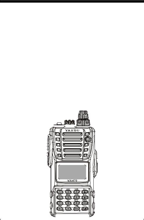
The VX-170 is a compact, high-performance FM hand-held providing up to five watts of RF power and wealth of convenient features for the 2-meter amateur band.
New and exciting features of the VX-170 are Enhanced Paging and Code Squelch (EPCS), that allows you to page a particular station and only receive calls from that station, if desired; and a security Password feature, that will allow you to turn on and operate your transceiver only after you enter your Password.
Additional features include a convenient access key for Vertex Standard’s WIRES™ (Widecoverage Internet Repeater Enhancement System), a transmit Time-Out Timer (TOT), Automatic Power-Off (APO), Automatic Repeater Shift (ARS), Vertex Standard’s exclusive ARTS™ (Auto-Range Transponder System) which “beeps” the user when you move out of communications range with another ARTS™ equipped station, plus provision for reduction of the TX deviation in areas of high channel congestion. And an RF squelch circuit allows the owner to set the squelch to open at a programmable setting of the S- Meter, thus reducing guesswork in setting the squelch threshold.
We appreciate your purchase of the VX-170, and encourage you to read this manual thoroughly, so as to learn about the many exciting features of your exciting new Vertex Standard hand-held transceiver!
|
|
|
|
|
|
|
|
|
|
|
|
|
|
|
|
|
|
|
|
|
|
|
|
|
|
|
|
|
|
|
|
|
|
|
|
|
|
|
|
|
|
|
|
|
|
|
|
|
|
|
|
|
|
|
|
|
|
|
|
|
|
|
|
|
|
|
|
|
|
|
|
|
|
|
|
|
|
|
|
|
|
|
|
|
|
|
|
|
|
|
|
|
|
|
|
|
|
|
|
|
|
|
|
|
|
|
|
|
|
|
|
|
|
|
|
|
|
|
|
|
|
|
|
|
|
|
|
|
|
|
|
|
|
|
|
|
|
|
|
|
|
|
|
|
|
|
|
|
|
|
|
|
|
|
|
|
|
|
|
|
|
|
|
|
|
|
|
|
|
|
|
|
|
|
|
|
|
|
|
|
|
|
|
|
|
|
|
|
|
|
|
|
|
|
|
|
|
|
|
|
|
|
|
|
|
|
|
|
|
|
|
|
|
|
|
|
|
|
|
|
|
|
|
|
|
|
|
|
|
|
|
|
|
|
|
|
|
|
|
|
|
|
|
|
|
|
|
|
|
|
|
|
|
|
|
|
|
|
|
|
|
|
|
|
|
|
|
|
|
|
|
|
|
|
|
|
|
|
|
|
|
|
|
|
|
|
|
|
|
|
|
|
|
|
|
|
|
|
|
|
|
|
|
|
|
|
|
VX-170 OPERATING MANUAL |
1 |
||||||||||||||||||||

ACCESSORIES & OPTIONS
|
SUPPLIED ACCESSORIES |
|
|
FNB-83 |
7.2 V, 1,400 mAh |
|
Rechargeable Nickel-Metal Hydride Battery Pack |
NC-88B |
Overnight Battery Charger (10-Hour) |
YHA-68 |
Antenna |
Quick Draw Belt Clip
Operating Manual
Warranty Card
|
AVAILABLE OPTIONS |
|
|
FNB-83 |
7.2 V, 1,400 mAh |
|
Rechargeable Nickel-Metal Hydride Battery Pack |
NC-88B/C/U |
Overnight Battery Charger (10-Hour) |
VAC-370 |
Desktop Rapid Charger |
CD-26 |
Charger Cradle |
FBA-25A |
Dry Cell Battery Case for 6 “AA” Alkaline Cells (not supplied) |
CN-3 |
BNC-to-SMAAdapter |
CT-91 |
Microphone Adapter |
E-DC-5B |
DC Cable with Cigarette-Lighter Adapter |
E-DC-6 |
DC Cable; plug and wire only |
MH-57A4B |
Speaker/Microphone |
CMP460A |
Waterproof Speaker/Microphone |
VC-27 |
Earpiece/Microphone |
VC-24 |
VOX Headset |
FTD-7 |
DTMF Paging Unit |
: “B” suffix is for use with 100-120 VAC, “C” suffix is for use with 230-240 VAC, and “U” suffix is for use with 230 VAC.
Availability of accessories may vary. Some accessories are supplied as standard per local requirements, while others may be unavailable in some regions. This product is designed to perform optimally when used with genuine Vertex Standard accessories. Vertex Standard shall not be liable for any damage to this product and/or accidents such as fire, leakage or explosion of a battery pack, etc., caused by the malfunction of nonVertex Standard accessories. Consult your Vertex Standard dealer for details regarding these and any newly-available options. Connection of any non-Vertex Standard-approved accessory, should it cause damage, may void the Limited Warranty on this apparatus.
2 |
VX-170 OPERATING MANUAL |

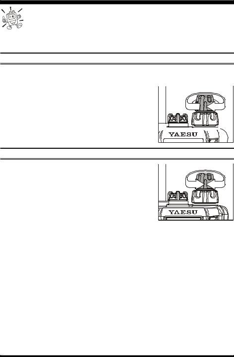
CONTROLS & CONNECTORS (TOP & FRONT PANELS)
Antenna Jack
Connect the supplied rubber flex antenna (or an-  other antenna presenting a 50-Ohm impedance)
  here.
here. 
MIC/SP Jack |
|
|
|
This four-conductor miniature jack provides con- |
|
|
|
nection points for microphone audio, earphone |
|
|
|
audio, PTT, and ground. |
|||
|
|
Do not allow the VX-170 to become submerged in water while the plastic 

 cover over the MIC/SP jack is removed.
VOL/PWR Knob
Turn this control clockwise to turn the radio on and to increase the volume. Counterclockwise rotation into the click-stop will turn the radio off.
DIAL Knob
This (inner) 20-position detented rotary switch is used for setting the operating frequency, and also is used for menu selections and other adjustments.
Speaker
The internal speaker is located here.
LCD (Liquid Crystal Display)
The display shows the current operating conditions, as described on the next page.
Keypad
These 16 keys select many of most important operating features on the VX-170. The functions of the keys are described in detail on the pages to follow.
TX/BUSY Indicator Lamp
This indicator glows green when the squelch opens, and turns red during transmit.
MIC
The internal microphone is located here.
|
|
VX-170 OPERATING MANUAL |
3 |
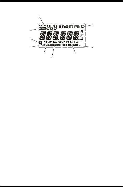
CONTROLS & CONNECTORS (LCD)
|
|
|
|
|
Memory Channel Number |
|||||||||||||||
Skip Memory Channel or |
|
Repeater Shift Direction |
||||||||||||||||||
Preferential Memory Channel |
|
|
|
|
|
|
|
|
CTCSS/DSC Operation |
|||||||||||
|
|
|
|
|
|
|
|
|
|
|
|
|
|
|||||||
Priority Channel |
|
|
|
|
|
|
|
|
|
|
|
|
|
|
|
|
|
|
|
Internet Connection |
|
|
|
|
|
|
|
|
|
|
|
|
|
|
|
|
|
|
|
||
Memory Bank Active |
|
|
|
|
|
|
|
|
|
|
|
|
|
Feature Active |
||||||
|
|
|
|
|||||||||||||||||
|
|
|
|
|||||||||||||||||
|
|
|
|
|
|
|
|
|
|
|
|
|
Bell Alerm Active |
|||||||
|
|
|
|
|
|
|
|
|
|
|
|
|
|
|
|
|
|
|
|
|
Secondary Keypad |
|
|
|
|
|
|
|
|
|
|
|
|
|
Operating Frequency |
||||||
|
|
|
|
|
|
|
|
|
|
|
|
|
||||||||
|
|
|
|
|
|
|
|
|
|
|
|
|
|
|||||||
Active |
|
|
|
|
|
|
|
|
|
|
|
|
|
Battery Indicator |
||||||
Low TX Power Selected |
|
|
|
|
|
|
|
|
|
|
|
|
|
|||||||
|
|
|
|
|
|
|
|
|
|
|
|
|
S- & PO Meter |
|||||||
DTMF Autodiale Active |
|
|
|
|
|
|
|
|
|
Key Lock Active |
||||||||||
|
|
|
|
|
|
|
|
|
|
|||||||||||
|
Dual Watch Active |
|
|
|
|
|
|
Automatic Power-Off Active |
||||||||||||
|
|
|
|
|
|
|
|
|
|
|
||||||||||
|
|
|
|
|
|
|
|
|
Battery Saver Active |
|||||||||||
4 |
VX-170 OPERATING MANUAL |
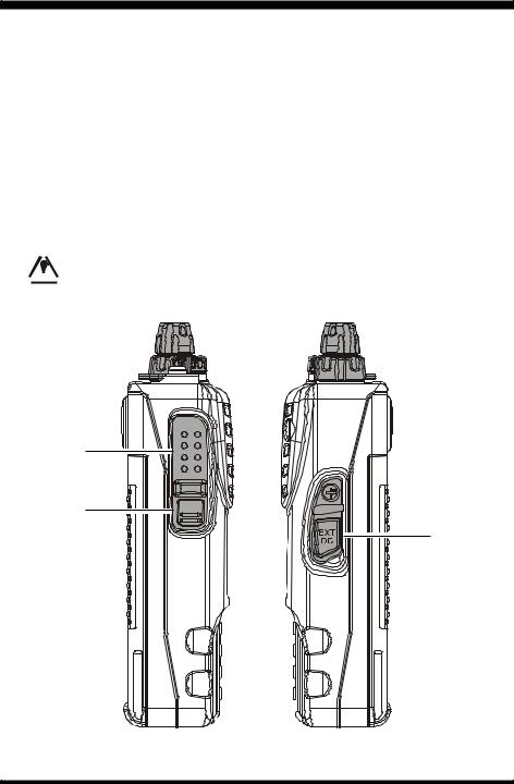
CONTROLS & CONNECTORS (SIDE PANEL)
PTT (Push To Talk) Switch
Press this switch to transmit, and release it (to receive) after your transmission is completed.
MONI Switch
Pressing this switch disables the noise squelching action, allowing you to hear very weak signals near the background noise level temporarily.
Press the [F] key on the keypad first, then press this switch to enable to adjustment of the squelch threshold level.
EXT DC Jack
This coaxial DC jack allows connection to an external DC power source (6-16V DC). The center pin of this jack is the Positive (+) connection.
 Do not allow the VX-170 to become submerged in water while the rubber

 cap over the EXT DC jack is removed.
VX-170 OPERATING MANUAL |
5 |
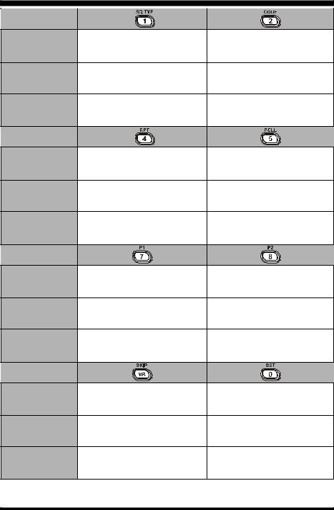
CONTROLS & CONNECTORS (KEYPAD FUNCTIONS)
Primary Function
Frequency entry digit “1.” Frequency entry digit “2.”
(PRESS KEY)
Secondary Function |
Activates the CTCSS or |
Selects the CTCSS tone or |
(PRESS [F] + KEY) |
DCS Operation. |
DCS code number. |
Third Function Toggles the “Weather” broadcast
Activates the ARTS feature.
(PRESS & HOLD KEY) channel memory bank on/off.
Primary Function |
Frequency entry digit “4.” |
Frequency entry digit “5.” |
|
(PRESS KEY) |
|||
|
|
||
Secondary Function |
Selects the direction of the uplink |
Selects the CTCSS/DCS Bell ringer |
|
frequency shift (either “–,” “+,” or |
|||
(PRESS [F] + KEY) |
repetitions. |
||
“simplex”) during repeater operation. |
|||
|
|
||
Third Function |
Activates the EMERGENCY |
None |
|
(PRESS & HOLD KEY) |
function. |
||
|
|||
|
1 |
1 |
|
Primary Function |
Frequency entry digit “7.” |
Frequency entry digit “8.” |
|
(PRESS KEY) |
|||
|
|
||
Secondary Function |
Selects the Scan Resume Mode. |
Selects the LCD/Keypad |
|
(PRESS [F] + KEY) |
|
Lamp Mode. |
|
Third Function |
None |
None |
|
(PRESS & HOLD KEY) |
|||
|
|
||
Primary Function |
Sets the frequency control to the |
Activates the Internet Connection |
|
Memory Recall mode. |
feature. |
||
(PRESS KEY) |
Activates the “Memory “Tune” mode |
||
Frequency entry digit “0.” |
|||
|
while in the Memory Recall mode. |
||
|
|
||
Secondary Function Selects the Memory Scan “Skip” |
Engages the Set (Menu) Mode. |
||
(PRESS [F] + KEY) |
channel-selection mode. |
||
|
|||
Third Function |
Starts the programmable scanner |
Enables Internet access code |
|
upward (toward a higher frequency |
|||
(PRESS & HOLD KEY) |
selection. |
||
or a higher channel number) |
|||
|
|
||
1: You can program the secondary (press [F] key +) function of the key to another function, if desired. See page 59 for details.
6 |
VX-170 OPERATING MANUAL |
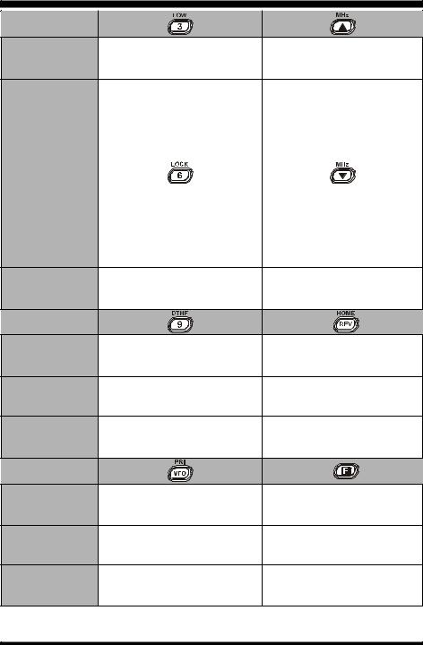
CONTROLS & CONNECTORS (KEYPAD FUNCTIONS)
Primary Function
Increases the VFO frequency by
Frequency entry digit “3.” one step or moves the memory
(PRESS KEY)
channel to the next-highest channel.
Secondary Function Selects the desired transmit power |
Tunes the VFO frequency |
||
(PRESS [F] + KEY) |
output level. |
upward in 1 MHz steps. |
|
|
|
|
|
Third Function |
|
Starts the scanner upward |
|
Activates the Smart Search feature. |
(toward a higher frequency or |
||
(PRESS & HOLD KEY) |
|||
|
a higher channel number). |
||
|
|
||
|
|
|
|
|
|
|
|
Primary Function |
|
Decreases the VFO frequency by |
|
Frequency entry digit “6.” |
one step or moves the memory |
||
(PRESS KEY) |
|||
|
channel to the next-lowest channel. |
||
|
|
||
|
|
|
|
Secondary Function |
Activates the Key Lockout feature. |
Tunes the VFO frequency |
|
(PRESS [F/W] + KEY) |
|
downward in 1 MHz steps. |
|
Starts the scanner downward Third Function Activates the Key Lockout feature. (toward a lower frequency or
(PRESS & HOLD KEY)
a lower channel number).
|
|
2 |
|
Primary Function |
|
Reverses the transmit and receive |
|
Frequency entry digit “9.” |
frequencies while working through a |
||
(PRESS KEY) |
|||
|
repeater. |
||
|
|
||
Secondary Function |
Selects the DTMF mode. |
Switches to the “Home” (favorite |
|
(PRESS [F] + KEY) |
frequency) Channel. |
||
|
|||
Third Function |
None |
None |
|
(PRESS & HOLD KEY) |
|||
|
|
||
Primary Function |
Sets frequency control to the VFO mode. |
Activates the “Alternate” key |
|
Toggles the VFO between “VFO A” and |
|||
(PRESS KEY) |
function. |
||
“VFO B” while in the VFO mode. |
|||
|
|
||
Secondary Function Activates the Priority (Dual Watch) |
Disables the “Alternate” key |
||
(PRESS [F] + KEY) |
function. |
function. |
|
|
Starts the programmed VFO scanner |
|
|
Third Function |
upward while in the VFO mode. |
Activates the “Memory Write” mode |
|
(PRESS & HOLD KEY) |
Selects the Memory Bank while in the |
(for memory channel storage). |
|
|
Memory Recall mode. |
|
|
2: You can exchange the function between the primary (press key) function and secondary (press [F] key +) function, if desired. See page 77 for details.
VX-170 OPERATING MANUAL |
7 |
INSTALLATION OF ACCESSORIES
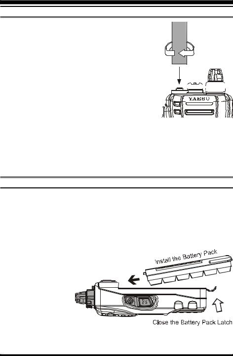
ANTENNA INSTALLATION
The supplied antenna provides good results over the entire frequency range of the transceiver. However, for enhanced reception on certain non-Amateur frequencies, you may wish to connect an antenna designed specifically for that frequency range, as the supplied antenna is necessarily a compromise outside the Amateur band, and cannot be expected to provide high performance at all frequencies.
To install the supplied antenna, hold the bottom end of the 


 antenna, then screw it onto the mating connector on the trans-


 ceiver until it is snug. Do not over-tighten by use of extreme
 force.

Notes:
Never transmit without having an antenna connected.
When installing the supplied antenna, never hold the upper part of the antenna while screwing it onto the mating connector on the transceiver.
If using an external antenna for transmission, ensure that the SWR presented to the transceiver is 1.5:1 or lower, to avoid excessive feedline loss.
INSTALLATION OF FNB-83 BATTERY PACK
The FNB-83 is a high-performance Ni-MH battery providing high capacity in a compact package. Under normal use, the FNB-83 may be used for approximately 300 charge cycles, after which operating time may be expected to decrease. If you have an old battery pack which is displaying capacity which has become diminished, you should replace the pack with a new one.
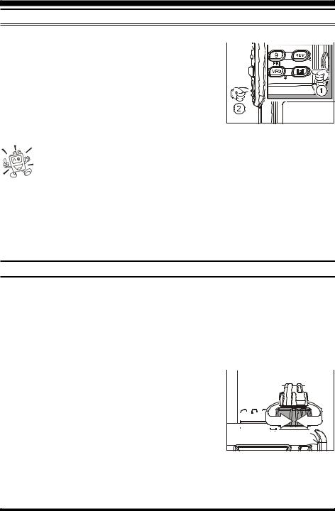
Installation of the battery is easy and quick:
Insert the battery pack into the battery compart-
ment on the back of the radio while tilting the Belt Clip outward, then close the Battery Pack Latch until it locks in place with a “Click.” 


To remove the battery, 


 turn the radio off and


remove any protective cases. Open the Battery
Pack Latch on the bot-
tom of the radio, then slide the battery downward and out from the radio while tilting the Belt Clip out of the way.
8 |
VX-170 OPERATING MANUAL |
INSTALLATION OF ACCESSORIES
BATTERY CHARGING
If the battery has never been used, or its charge is depleted, it may be charged by connecting the NC-88 Overnight Battery Charger, as shown in the illustration, to the EXT DC jack. If only 12 ~ 16 Volt DC power is available, the optional E-DC-5B DC Cable (with its cigarette lighter plug) or E-DC-6 DC Cable (plug and wire only) may also be used for charging the battery.
A fully-discharged pack will be charged completely in 10 hours. Disconnect the NC-88 from the EXT DC jack and the AC line outlet.
NC-88 |
E-DC-5B |
E-DC-6 |
Important Note
The NC-88 is not designed to power the transceiver for operation (reception or transmission).
Do not leave the NC-88 connected to the transceiver for continuous periods in excess of 24 hours. Long term overcharging can degrade the Ni-MH battery pack and significantly shorten its useful life.
Please be advised that the NC-88 may contribute noise to TV and radio reception in the immediate vicinity, so we do not recommend its use adjacent to such devices.
LOW BATTERY INDICATION
As your battery discharges during use, the voltage will gradually become lower. When the battery voltage is becoming too low for reliable operation, 
the “  ” icon will blink on the LCD display, indicating that the battery pack must be recharged before further use.
Avoid recharging Ni-MH batteries before the “ ”indicator is
observed, as this can degrade the charge capacity of your Ni-MH battery pack.
VX-170 OPERATING MANUAL |
9 |
INSTALLATION OF ACCESSORIES
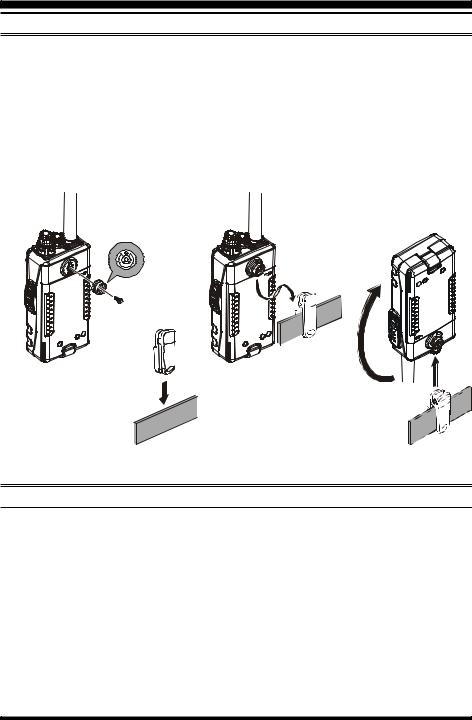
BELT CLIP INSTALLATION
Connect the hanger to the rear of the VX-170, with the notch pointing directly up, using the supplied screw (Figure 1). Use only the screw included with the clip to mount the clip to the back of the VX-170.
Clip the Quick-Draw Belt Clip onto your belt (Figure 2).
To install the VX-170 into the Quick-Draw Belt Clip, align the hanger with the QuickDraw Belt Clip, and slide the VX-170 into its slot until a click is heard (Figure 3).
To remove the VX-170 from the Quick-Draw Belt Clip, rotate the VX-170 180 degrees, then slide the VX-170 out from the Quick-Draw Belt Clip (Figure 4).
Figure 3
Figure 2 |
Figure 4 |
INSTALLATION OF FBA-25A ALKALINE BATTERY CASE (OPTION)
The optional FBA-25A Battery Case allows operation of the VX-170 using six “AA” size Alkaline batteries.
When installing batteries, insert the (–) end first, then press in the (+) end so the battery snaps into place. Always replace all six batteries at the same time, paying attention to the polarity indicated inside the case.
The FBA-25A must not be used with rechargeable cells. The FBA-25A does not contain the thermal and over-current protection circuits (provided in the “FNB” series of Ni-MH Battery Packs) required when utilizing Ni-Cd and Ni-MH cells.
Note that the power output and battery life will be much shorter when using Alkaline AA cells. They should be considered an emergency backup power source only, for this reason.
10 |
VX-170 OPERATING MANUAL |
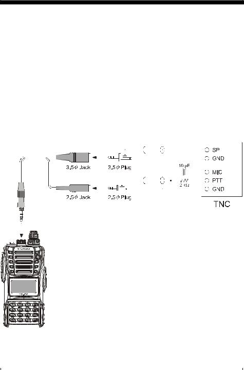
INTERFACE OF PACKET TNCS
The VX-170 may be used for Packet operation, using the optional CT-91 Microphone Adapter (available from your Yaesu dealer) for easy interconnection to commonly-avail- able connectors wired to your TNC. You may also build your own cable, using a fourconductor miniature phone plug, per the diagram below.
The audio level from the receiver to the TNC may be adjusted by using the VOL knob, as with voice operation. The input level to the VX-170 from the TNC should be adjusted at the TNC side; the optimum input voltage is approximately 5 mV at 2000 Ohms.
Be sure to turn the transceiver and TNC off before connecting the cables, so as to prevent voltage spikes from possibly damaging your transceiver.
When you are operating on Packet, switch the Receive Battery Saver OFF, as the “sleep” cycle may “collide” with the beginning of an incoming Packet transmission, causing your TNC not to receive the full data burst. See page 60 for details regarding Battery Saver setup.
|
|
|
|
|
|
|
|
|
|
|
|
|
|
|
|
|
|
|
|
|
|
|
|
|
|
|
|
|
|
|
|
|
|
|
|
|
|
|
|
|
|
|
|
|
|
|
|
|
|
|
|
|
|
|
|
|
|
|
|
|
|
|
|
|
|
|
|
|
|
|
|
|
|
|
|
|
|
|
|
|
|
|
|
|
|
|
|
|
|
|
|
|
|
|
|
|
|
|
|
|
|
|
|
|
|
|
|
|
|
|
|
|
|
|
|
|
|
|
|
|
|
|
|
|
|
|
|
|
|
|
|
|
|
|
|
|
|
|
|
|
|
|
|
|
|
|
|
|
|
|
|
|
|
|
|
|
|
|
|
|
|
|
|
|
|
|
|
|
|
|
|
|
|
|
|
|
|
|
|
|
|
|
|
|
|
|
|
|
|
|
|
|
|
|
|
|
|
|
|
|
|
|
|
|
|
|
|
|
|
|
|
|
|
|
|
|
|
|
|
|
|
|
|
|
|
|
|
|
|
|
|
|
|
|
|
|
|
|
|
|
|
|
|
|
|
|
|
|
|
|
|
|
|
|
|
|
|
|
|
|
|
|
|
|
|
|
|
|
|
|
|
|
|
|
|
|
|
|
|
|
|
|
|
|
|
|
|
|
|
|
|
|
|
|
|
|
|
|
|
|
|
|
|
|
|
|
|
|
|
|
|
|
|
|
|
|
|
|
|
|
|
|
|
|
|
|
|
|
|
|
|
|
|
|
|
|
|
|
|
|
|
|
|
|
|
|
|
|
|
|
|
|
|
|
|
|
|
|
|
|
|
|
|
|
|
|
|
|
|
|
|
|
|
|
|
|
|
|
|
|
|
|
|
|
|
|
|
|
|
|
|
|
|
|
|
|
|
|
|
|
|
|
|
|
|
|
|
|
|
|
|
|
|
|
|
|
|
|
|
|
|
|
|
|
|
|
|
|
|
|
|
|
|
|
|
|
|
|
|
|
|
|
|
|
|
|
|
|
|
|
|
|
|
|
|
|
|
|
|
|
|
|
|
|
|
|
|
|
|
|
|
|
|
|
|
|
|
|
|
|
|
|
|
|
|
|
|
|
|
|
|
|
|
|
|
|
|
|
|
|
|
|
|
|
|
|
|
|
|
|
|
|
|
|
|
|
|
|
|
|
|
|
|
|
|
|
|
|
|
|
|
|
|
|
|
|
|
|
|
|
|
|
|
|
|
|
|
|
|
|
|
|
|
|
|
|
|
|
|
|
|
|
|
|
|
|
|
|
|
|
|
|
|
|
|
|
|
|
|
|
|
|
|
|
|
|
|
|
|
|
|
|
|
|
|
|
|
|
|
|
|
|
|
|
|
|
|
|
|
|
|
|
|
|
|
|
|
|
|
|
|
|
|
|
|
|
|
|
|
|
|
|
|
|
|
|
|
|
|
|
|
|
|
|
|
|
|
|
|
|
|
|
|
|
|
|
|
|
|
|
|
|
|
|
|
|
|
|
|
|
|
|
|
|
|
|
|
|
|
|
|
|
|
|
|
|
|
|
|
|
|
|
|
|
|
|
|
|
|
|
|
|
|
|
|
|
|
|
|
|
|
|
|
|
|
|
|
|
|
|
|
|
|
|
|
|
|
|
|
|
|
|
|
|
|
|
|
|
|
|
|
|
|
|
|
|
|
|
|
|
|
|
|
|
|
|
|
|
|
|
|
|
|
|
|
|
|
|
|
|
|
|
|
|
|
|
|
|
|
|
|
|
|
|
|
|
|
|
|
|
|
|
|
|
|
|
|
|
|
|
|
|
|
|
|
|
|
|
|
|
|
|
|
|
|
|
|
|
|
|
|
|
|
|
|
|
|
|
|
|
|
|
|
|
|
|
|
|
|
|
|
|
|
|
|
|
|
|
|
|
|
|
|
|
|
|
|
|
|
|
|
|
|
|
|
|
|
|
|
|
|
|
|
|
|
|
|
|
|
|
|
|
|
|
|
|
|
|
|
|
|
|
|
|
|
|
|
|
|
|
|
|
|
|
|
|
|
|
|
|
|
|
|
|
|
|
|
|
|
|
|
|
|
|
|
|
|
|
|
|
|
|
|
|
|
|
|
|
|
|
|
|
|
|
|
|
|
|
|
|
|
|
|
|
|
|
|
|
|
|
|
|
|
|
|
|
|
|
|
|
|
|
|
|
|
|
|
|
|
|
|
|
|
|
|
|
|
|
|
|
|
|
|
|
|
|
|
|
|
|
|
|
|
|
|
|
|
|
|
|
|
|
|
|
|
|
|
|
|
|
|
|
|
|
|
|
|
|
|
|
|
|
|
|
|
|
|
|
|
|
|
|
|
|
|
|
|
|
|
|
|
|
|
|
|
|
|
|
|
|
|
|
|
|
|
|
|
|
|
|
|
|
|
|
|
|
|
|
|
|
|
|
|
|
|
|
|
|
|
|
|
|
|
|
|
|
|
|
|
|
|
|
|
|
|
|
|
|
|
|
|
|
|
|
|
|
|
|
|
|
|
|
|
|
|
|
|
|
|
|
|
|
|
|
|
|
|
|
|
|
|
|
|
|
|
|
|
|
|
|
|
|
|
|
|
|
|
|
|
|
|
|
|
|
|
|
|
|
|
|
|
|
|
|
|
|
|
|
|
|
|
|
|
|
|
|
|
|
|
|
|
|
|
|
|
|
|
|
|
|
|
|
|
|
|
|
|
|
|
|
|
|
|
|
|
|
|
|
|
|
|
|
|
|
|
|
|
|
|
|
|
|
|
|
|
|
|
|
|
|
|
|
|
|
|
|
|
|
|
|
|
|
|
|
|
|
|
|
|
|
|
|
|
|
|
|
|
|
|
|
|
|
|
|
|
|
|
|
|
|
|
|
|
|
|
|
|
|
|
|
|
|
|
|
|
|
|
|
|
|
|
|
|
|
|
|
|
|
|
|
|
|
|
|
|
|
|
|
|
|
|
|
|
|
|
|
|
|
|
|
|
|
|
|
|
|
|
|
|
|
|
|
|
|
|
|
|
|
|
|
|
|
|
|
|
|
|
|
|
|
|
|
|
|
|
|
|
|
|
|
|
|
|
|
|
|
|
|
|
|
|
|
|
|
|
|
|
|
|
|
|
|
|
|
|
|
|
|
|
|
|
|
|
|
|
|
|
|
|
|
|
|
|
|
|
|
|
|
|
|
|
|
|
|
|
|
|
|
|
|
|
|
|
|
|
|
|
|
|
|
|
|
|
|
|
|
|
|
|
|
|
|
|
|
|
|
|
|
|
|
|
|
|
|
|
|
|
|
|
|
|
|
|
|
|
|
|
|
|
|
|
|
|
VX-170 OPERATING MANUAL |
11 |
|||||||||||||||||||||||||||||||||||||||||||||||||||
OPERATION
Hi! I’m R. F. Radio, and I’ll be helping you along as you learn the many features of the VX-170. I know you’re anxious to get on the air, but I encourage you to read the “Operation” section of this manual as thoroughly as
possible, so you’ll get the most out of this fantastic new transceiver. Now. . .let’s get operating!
SWITCHING POWER ON AND OFF
Be sure the Battery Pack is installed, and that the battery is fully charged. Connect the antenna to the top panel ANTENNA jack.
Rotate the top panel’s VOL/PWR knob (inner knob) 
out of the click-stop to turn on the radio. The current DC supply voltage will be indicated on the display for 2 seconds. After this 2 second interval, the display will resume its normal indication of the operating frequency.
To turn the radio off, turn the VOL/PWR knob fully 
 counter-clockwise into the click stop position.


ADJUSTING THE AUDIO VOLUME LEVEL
Rotate the VOL/PWR knob (inner knob) to adjust the re-  ceiver level for a comfortable listing level, using the back-
 ground noise as a reference. Clockwise rotation increases
the volume level.
12 |
VX-170 OPERATING MANUAL |
OPERATION
SQUELCH ADJUSTMENT
To set the squelch, press the [F] key, followed by the MONI switch just below the PTT switch on the left side of the transceiver. 
Now rotate the DIAL (outer knob) to find the lowest setting (“LVL 1” through “LVL 15”) that will just silence the background noise. Do not use a higher setting than necessary, or sensitivity to weak incoming signals will be degraded.
Press the PTT switch momentarily when you’ve made
the new setting; this will return you to normal operation (without having transmitted).
1)A special “RF Squelch” feature is provided on this radio. This feature allows you to set the squelch so that only signals exceeding a certain S-meter
level will open the squelch. See page 18 for details.
2) If you’re operating in an area of high RF pollution, you may need to consider “Tone Squelch” operation using the built-in CTCSS Decoder. This feature will keep your radio quiet until a call is received from a station sending a carrier which contains a matching (subaudible) CTCSS tone. Or, if your friends have radios equipped with DCS (Digital Coded Squelch) like your VX-170 has, try using that mode for silent monitoring of busy channels.
FREQUENCY NAVIGATION
The VX-170 will initially be operating in the “VFO” mode, a channelized system which allows free tuning throughout the currently-selected operating band.
Three basic frequency navigation methods are available on the VX-170:
1) Tuning Dial
Rotation of the DIAL (outer knob) allows tuning in the pre-programmed steps established for the current operating band. Clockwise rotation of the DIAL causes the VX-170 to be tuned toward a higher frequency, while counter-clockwise  rotation will lower the operating frequency.


If you press the [F] key momentarily, then rotate the DIAL, 
 frequency steps of 1 MHz will be selected. This feature is


 extremely useful for making rapid frequency excursions over
  the wide tuning range of the VX-170.
VX-170 OPERATING MANUAL |
13 |
OPERATION
FREQUENCY NAVIGATION
2) Direct Keypad Frequency Entry
The desired operating frequency may be entered directly from the keypad. The first “1” in the frequency does not need to be entered, as it is “assumed” by the microprocessor.
To enter a frequency directly, just key in the 10 MHz, 1 MHz, and the kHz digits.
Examples:To enter 146.560 MHz, press [4] [6] [5] [6] [0]
To enter 146.5625 MHz (12.5 kHz steps), [4] [6] [5] [6] [2]
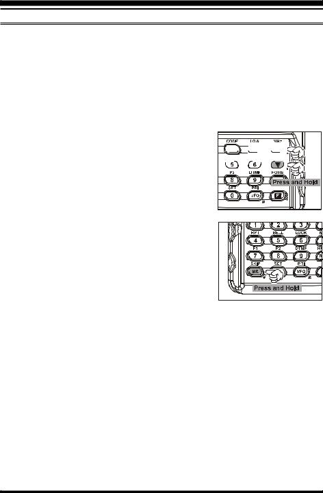
3) Scanning
Press and hold in either the [ (MHz)] or [ (MHz)] key for one second to initiate upward or downward scanning, 


 respectively (Manual VFO Scan).


For scanning within a limited sub-band range, from the VFO mode, press and hold in the [MR(SKIP)] key for one second to begin scanning toward a higher frequency within the previously-defined sub-band (Programmed VFO Scan). Details regarding sub-band setup may be found on page 37.
If you wish to reverse the direction of the scan (i.e. toward a lower frequency, instead of a higher frequency), just rotate the DIAL one click in the counter-clockwise direction while the VX-170 is scanning. The scanning direction will be reversed. To revert to scanning toward a higher frequency once more, rotate the DIAL one click clockwise.
(MANUAL VFO SCAN)
(PROGRAMMED VFO SCAN)
The scanner will stop when it receives a signal strong enough to break through the Squelch threshold. The VX-170 will then hold on that frequency according to the setting of the “RESUME” mode (Set Mode Item 32: RESUME). Press the PTT switch momentarily to cancel the scanning. This only stops the scan; it does not cause transmission to occur. See page 36 for details regarding Scan Operation.
14 |
VX-170 OPERATING MANUAL |
OPERATION
TRANSMISSION
Once you have set up an appropriate frequency inside the 144 MHz Amateur band on which the VX-170 can transmit, you’re ready to go on the air! These are the most basic steps; more advanced aspects of transmitter operation will be discussed later.
To transmit, press the PTT switch, and speak into the front panel microphone (located in the lower left-hand corner of the speaker grille) in a normal voice level. The TX/BUSY indicator will glow red during transmission.
To return to the receive mode, release the PTT switch.During transmission, the relative power level will be
indicated on the bar graph at the bottom of the LCD; full scale deflection confirms “High Power” operation, while deflection of two bars indicates “Low Power” operation. Five bars indicate “Medium Power” operation. Additionally, the “LOW” icon will appear at the bottom of the display while operating on the “Low Power” and “Medium Power” settings.
1) If you’re just talking to friends in the immediate area, you’ll get much longer battery life by switching to Low Power operation, described in the next chapter. And don’t
forget: always have an antenna connected when you transmit.
2) Transmission is possible only on the 144 MHz amateur band.
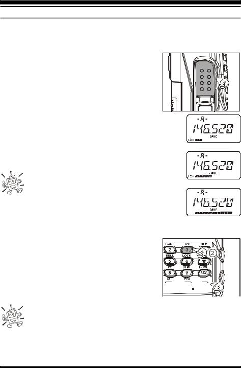
“LOW” POWER
“MID” POWER
“HIGH” POWER
Changing the Transmitter Power Level
To change the power level:
Press the [F] key, then press the [3(LOW)] key. The LCD shows the current power output level.
Rotate the DIAL knob to select the desired power output level.Available selections are “HIGH” (5 W), “MID” (2 W), and “LOW” (0.5 W).
When you have made your choice, press the PTT switch 


 to save the new setting and return to normal operation.
1) The VX-170 is smart! When you store memories, you can store the power output settings separately in each memory, so you don’t waste battery power when using very close-in repeaters!
2) When you are operating on the “Low” or “Medium” power setting, you can press the [F] key, then press the PTT switch, to cause the VX-170 to transmit (temporarily) on High power. After one transmission, the power level will revert to the previously-se- lected (“Low” or “Medium” power) setting.
VX-170 OPERATING MANUAL |
15 |
ADVANCED OPERATION
Now that you’re mastered the basics of VX-170 operation, let’s learn more about some of the really neat features.
KEYBOARD LOCKING
In order to prevent accidental frequency change or inadvertent transmission, various aspects of the VX-170’s DIAL and keypad may be locked out. The possible lockout combinations are:
LK KEY: Just the front panel keypad is locked out LKDIAL: Just the top panel DIAL is locked out
LK K+D:Both the keypad and DIAL are locked out (factory default) LK PTT: The PTT switch is locked out (TX not possible)
LK P+K: Both the PTT switch and keypad are locked out LK P+D:Both the PTT switch and DIAL are locked out LK ALL: All of the above are locked out
To lock out some or all of the keys:
1. Press the [F] key, then press the [0(SET)] key to enter the Set mode.
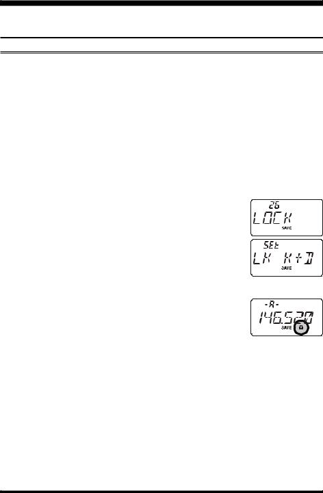
2. Rotate the DIAL knob to select Set Mode Item 26: LOCK.
3. Press the [F] key momentarily to enable adjustment of this Item. 4. Rotate the DIAL knob to choose between one of the locking
schemes as outlined above.
5.When you have made your selection, press the PTT switch to save the new setting and return to normal operation.
To activate the locking feature, (1) press and hold in the [6(LOCK)] key for one second, or (2) press the [F] key, followed by the [6(LOCK)] key. The “ ” icon will appear on the LCD. To cancel locking, repeat one of these processes.
16 |
VX-170 OPERATING MANUAL |
ADVANCED OPERATION
KEYPAD/LCD ILLUMINATION
Your VX-170 includes a reddish illumination lamp which aids in nighttime operation. The reddish illumination yields clear viewing of the display in a dark environment, with minimal degradation of your night vision.
Three options for activating the lamp are provided:
KEY Mode: Illuminates the Keypad/LCD lamp for five seconds when you rotate the DIAL knob or press the keypad or any switch (except PTT switch). This is the factory-programmed default setting.
CONT Mode: Illuminates the Keypad/LCD lamp continuously. OFF Mode: Disables the Keypad/LCD lamp.
Here is the procedure for setting up the Lamp operating mode:
1. Press the [F] key, then press the [0(SET)] key to enter the Set mode.
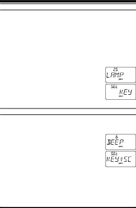
2. Rotate the DIAL knob to select Set Mode Item 25: LAMP.
3. Press the [F] key momentarily to enable adjustment of this Item. 4. Rotate the DIAL knob to select one of the three modes described
above.
5.When you have made your choice, press the PTT switch to save the new setting and return to normal operation.
DISABLING THE KEYPAD BEEPER
A keypad beeper provides useful audible feedback whenever a keypad is pressed.
If you want to turn the beep off:
1. Press the [F] key, then press the [0(SET)] key to enter the Set mode.
2. Rotate the DIAL knob to select Set Mode Item 6: BEEP.
3. Press the [F] key momentarily to enable adjustment of this Item. 4. Rotate the DIAL knob to change the setting to “OFF.” 5. Press the PTT switch to save the new setting and return to nor-
mal operation. 6. To turn the beep back on again, select “KEY” or “KEY+SC (fac-
tory default)” in step 4 above.
The beeper sounds when you press the keypad.
KEY+SC: The beeper sounds when you press the keypad, or when the scanner stops.
VX-170 OPERATING MANUAL |
17 |
ADVANCED OPERATION
RF SQUELCH
A special RF Squelch feature is provided on this radio. This feature allows you to set the squelch so that only signals exceeding a certain S-meter level will open the squelch.
To set up the RF squelch circuit for operation, use the following procedure: 1. Press the [F] key, then press the [0(SET)] key to enter the Set mode.
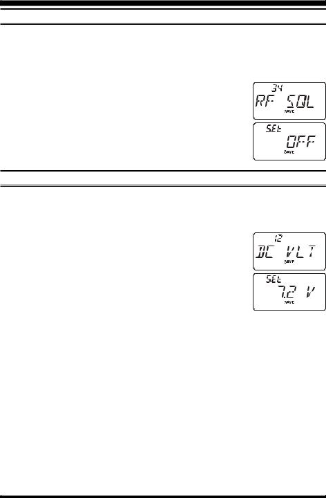
2. Rotate the DIAL knob to select Set Mode Item 34: RF SQL.
3. Press the [F] key momentarily to enable adjustment of this Item. 4. Rotate the DIAL knob to select the desired signal strength level
for the squelch threshold (S-1, S-2, S-3, S-4, S-5, S-6, S-8,
S-FULL, or OFF). 5. Press the PTT switch to save the new setting and return to nor-
mal operation.
CHECKING THE BATTERY VOLTAGE
The VX-170’s microprocessor includes programming which will measure the current battery voltage.
1. Press the [F] key, then press the [0(SET)] key to enter the Set mode.
2. Rotate the DIAL knob to select Set Mode Item 12: DC VLT.
3. Press the [F] key momentarily to display the current DC voltage being supplied.
4. Press the [F] key, followed by the PTT switch to return to normal operation.
18 |
VX-170 OPERATING MANUAL |
REPEATER OPERATION
Repeater stations, usually located on mountaintops or other high locations, provide a dramatic extension of the communication range for low-powered hand-held or mobile transceivers. The VX-170 includes a number of features which make repeater operation simple and enjoyable.
REPEATER SHIFTS
The VX-170 has been configured, at the factory, with the repeater shift set to 600 kHz.
Depending on the part of the band in which you are operating, the repeater shift may be either downward (–) or upward (+), and one of these icons will appear at the top of the LCD when repeater shifts have been enabled.
AUTOMATIC REPEATER SHIFT (ARS)
The VX-170 provides a convenient Automatic Repeater Shift feature, which causes the appropriate repeater shift to be applied automatically whenever you tune into the designated repeater sub-bands in your country. These sub-bands are shown below.
If the ARS feature does not appear to be working, you may have accidentally disabled it.
To re-enable ARS:
1. Press the [F] key, then press the [0(SET)] key to enter the Set mode.
2. Rotate the DIAL knob to select Set Mode Item 4: ARS. 3. Press the [F] key momentarily to enable adjustment of this Item. 4. Rotate the DIAL knob to select “ARS. ON.” 5. When you have made your selection, press the PTT switch to
save the new setting and return to normal operation.
ARS-Repeater Subbands
USA Version
145.1 |
145.5 |
146.0 |
146.4 |
147.0 |
|
147.6 |
148.0 |
||||||||||
|
|
|
|
|
|
|
|
|
|
|
|
|
|
|
|
|
|
|
|
|
|
|
|
|
|
|
|
|
|
|
|
|
|
|
|
|
|
|
|
|
|
|
|
|
|
|
|
|
|
|
|
|
|
146.6 147.4
145.6 145.8
EXP Version
VX-170 OPERATING MANUAL |
19 |
REPEATER OPERATION
MANUAL REPEATER SHIFT ACTIVATION
If the ARS feature has been disabled, or if you need to set a repeater shift direction other than that established by the ARS, you may set the direction of the repeater shift manually.
To do this:
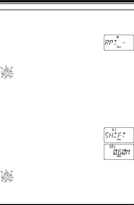
1. Press the [F] key, then press the [4(RPT)] key to enable selection of the repeater shift direction.
2. This provides a “short-cut” to Set Mode Item 35: RPT.MOD. 3. Rotate the DIAL knob to select the desired shift among “RPT.–,”
“RPT.+,” and “RPT.OFF.”
4.When you have made your selection, press the PTT switch to save the new setting and return to normal operation.
If you make a change in the shift direction, but still have Automatic Repeater Shift still engaged (see previous section), when you change frequency (by rotating the DIAL knob, for example) the ARS will over-ride your manual
setting of the shift direction. Turn ARS off if you do not wish this to happen.
If you make a change in the repeater shift on a memory channel that you already stored, the radio will consider this a “temporary” change unless you store the memory once more, this time with the desired repeater shift engaged.
Changing the Default Repeater Shifts
If you travel to a different region, you may need to change the default repeater shift so as to ensure compatibility with local operating requirements.
To do this, follow the procedure below:
1. Press the [F] key, then press the [0(SET)] key to enter the Set mode.
2. Rotate the DIAL knob to select Set Mode Item 41: SHIFT.
3. Press the [F] key momentarily to enable adjustment of this Item. 4. Rotate the DIAL knob to select the new repeater shift magni-
tude.
5.When you have made your selection, press the PTT switch to save the new setting and return to normal operation.
If you just have one “odd” split that you need to program, don’t change the “default” repeated shifts using this Set Mode Item. Enter the transmit and receive frequencies separately, as shown on page 29.
20 |
VX-170 OPERATING MANUAL |
REPEATER OPERATION
MANUAL REPEATER SHIFT ACTIVATION
Checking the Repeater Uplink (Input) Frequency
It often is helpful to be able to check the uplink (input) frequency of a repeater, to see if the calling station is within direct (“Simplex”) range.
To do this, just press the [REV(HOME)] key. You’ll notice  that the display has shifted to the repeater uplink frequency.


 Press the [REV(HOME)] key again to cause operation to


 revert to normal monitoring of the repeater downlink (out-


 put) frequency. While you are listening on the input fre-


 quency to the repeater using the [REV(HOME)] key, the
repeater offset icon will blink.
The configuration of this key may be set either to “RV” (for checking the input frequency of a repeater), or “HM” (for instant switching to the “Home” channel for the band you are operating on). To change the configuration of this key, use Set Mode Item 33: REV/HM. See page 77.
VFO SPLIT MODE
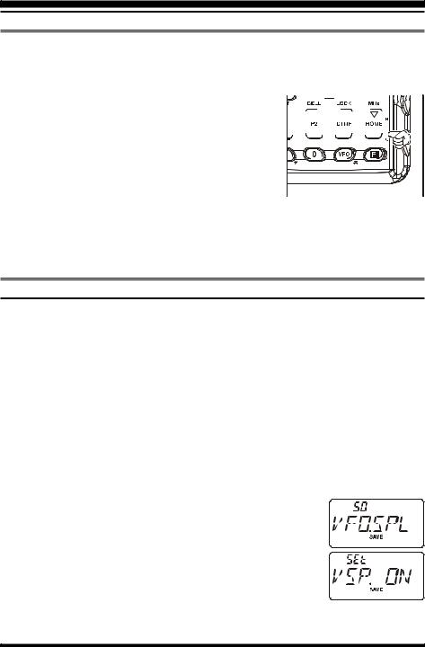
For working on repeaters with odd splits, or communicating with astronauts on orbiting space vehicles, it may be necessary to use non-standard splits between the receive and transmit frequency. If the application is infrequent enough not to warrant the dedication of a memory channel for this purpose, the “VFO Split” mode may be used. Here is the procedure for going Split:
1.Press the [VFO(PRI)] key, as needed, to select VFO-A. Set VFO-A for the desired receiving (downlink) frequency (e.g.145.800 MHz).
2.Now press the [VFO(PRI)] key, and set VFO-B for the desired transmit (uplink) frequency (e.g. 144.490 MHz).
3.Press the [VFO(PRI)] key once more to re-establish VFO-A as the “Main” (receive) VFO.
4.Press the [F] key, then press the [0(SET)] key to enter the Set mode.
5. Rotate the DIAL to select Set Mode Item 50: VFO.SPL.
6. Press the [F] key, then rotate the DIAL to set this function “VSP. ON.”
7. Press the PTT switch once to save the new setting and exit to
normal operation. 8. You will now be operating in the Split mode. When you press
the PTT switch to transmit, you will observe that VFO-A and
VFO-B will reverse positions. The VFO selection indicator “-b-” will blink while the transceiver is transmitting, this means that the VFO Split feature is now activated.
VX-170 OPERATING MANUAL |
21 |

REPEATER OPERATION
VFO SPLIT MODE
9.If you need to modify the VFO-B (transmit) frequency (for Doppler Shift correction, etc.), just press the [VFO(PRI)] key, then make the necessary change, then press [VFO(PRI)] key once more to restore VFO-A to the “receive VFO” position.
10.When you have finished with Split operation, re-enter the Set mode, and change Set Mode Item 50: VFO.SPL to “VSP.OFF.”
Asplit frequency pair set up via the VFO Split feature cannot be stored directly into memory. You can, however, store odd frequency pairs using a different (slightly simpler) procedure. See page 29.
22 |
VX-170 OPERATING MANUAL |
CTCSS/DCS/EPCS OPERATION
CTCSS OPERATION
Many repeater systems require that a very-low-frequency audio tone be superimposed on your FM carrier in order to activate the repeater. This helps prevent false activation of the repeater by radar or spurious signals from other transmitters. This tone system, called “CTCSS” (Continuous Tone Coded Squelch System), is included in your VX-170, and is very easy to activate.
CTCSS setup involves two actions: setting the Tone Mode and then setting of the Tone Frequency. These actions are set up by using the [1(SQ TYP)] key and [2(CODE)] keys.
1.Press the [F] key, then press the [1(SQ TYP)] key to enable selection of the CTCSS/ DCS/ECS mode.
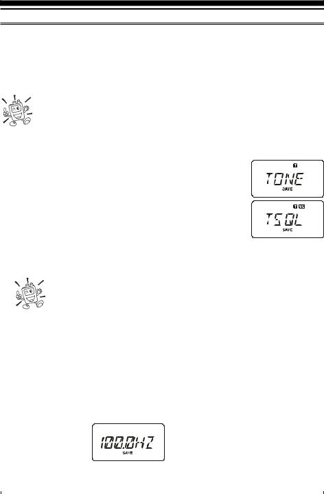
2.Rotate the DIAL knob so that “TONE” indication appears on the
display; this activates the CTCSS Encoder, for access to repeaters requiring a CTCSS tone.
3. Rotation of the DIAL knob one more “click” in step “2” above
will cause the “TSQL” notation to appear. When “TSQL” is displayed, this means that the Tone SQueLch system is active, which mutes your VX-170’s receiver until it receives a call from an-
other radio sending out a matching CTCSS tone. This can help keep your radio quiet until a specific call is received, which may be helpful while operating in congested areas of the band.
1) You may notice a “REV TN” indication on the display while you rotate the DIAL knob in this step; this means that the Reverse Tone Squelch system is active, which mutes your VX-170’s receiver (instead of opening
the squelch) when it receives a call from the radio sending a matched CTCSS tone. The “
 ” icon will blink on the display when the Reverse Tone Squelch system is activated.
2) You may notice the “DCS” and “ECS” indications on the display while you rotate the DIAL knob still more. We’ll discuss the Digital Code Squelch system (for “DCS”) and Enhanced Paging & Code Squelch (for “ECS”) later.
4. |
When you have made your selection of the CTCSS tone mode, press the PTT switch |
||||||||
|
to save the new setting. |
|
|
|
|
|
|
|
|
|
|
CTCSS TONE FREQUENCY (Hz) |
|
||||||
5. |
Press the [F] key, then press the |
67.0 |
|
69.3 |
71.9 |
74.4 |
77.0 |
|
79.7 |
82.5 |
|
85.4 |
88.5 |
91.5 |
94.8 |
|
97.4 |
||
|
[2(CODE)] key to |
|
|
||||||
|
100.0 |
|
103.5 |
107.2 |
110.9 |
114.8 |
|
118.8 |
|
|
|
|
|
||||||
|
enable adjustment |
123.0 |
|
127.3 |
131.8 |
136.5 |
141.3 |
|
146.2 |
|
of the CTCSS fre- |
151.4 |
|
156.7 |
159.8 |
162.2 |
165.5 |
|
167.9 |
|
quency. |
171.3 |
|
173.8 |
177.3 |
179.9 |
183.5 |
|
186.2 |
|
189.9 |
|
192.8 |
196.6 |
199.5 |
203.5 |
|
206.5 |
|
6. |
Rotate the DIAL knob until the display |
|
|
||||||
210.7 |
|
218.1 |
225.7 |
229.1 |
233.6 |
|
241.8 |
||
|
indicates the Tone Frequency you need to |
250.3 |
|
254.1 |
– |
– |
– |
|
– |
|
|
|
|
|
|
|
|
|
|
VX-170 OPERATING MANUAL |
23 |

CTCSS/DCS/EPCS OPERATION
CTCSS OPERATION
be using (ask the repeater owner/operator if you don’t know the tone frequency).
7.When you have made your selection, press the [F] key momentarily to save the new settings and exit to normal operation. This is different than the usual method of restoring normal operation, and it applies only to the configuration of the CTCSS/DCS frequencies.
Your repeater may or may not re-transmit a CTCSS tone - some systems just use CTCSS to control access to the repeater, but don’t pass it along when transmitting. If the S-Meter deflects, but the VX-170 is not passing audio, repeat steps “1” through “4” above, but rotate the DIAL so that “TSQ” disappears - this
will allow you to hear all traffic on the channel being utilized.
DCS OPERATION
Another form of tone access control is Digital Code Squelch, or DCS. It is a newer, more advanced tone system which generally provides more immunity from false paging than does CTCSS. The DCS Encoder/Decoder is built into your VX-170, and operation is very similar to that just described for CTCSS. Your repeater system may be configured for DCS; if not, DCS is frequently quite useful in Simplex operation if your friend(s) use transceivers equipped with this advanced feature.
Just as in CTCSS operation, DCS requires that you set the Tone Mode to DCS and that you select a tone code.
1.Press the [F] key, then press the [1(SQ TYP)] key to enable selection of the CTCSS/ DCS/ECS mode.
2. Rotate the DIAL knob until the “DCS” indication appears on the display; this activates the DCS Encoder/Decoder.
3.Press the PTT switch to save the new setting.
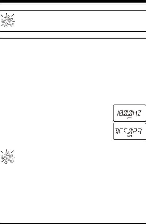
4.Press the [F] key, then press the [2(CODE)] key to enable adjustment of the DCS code.
5.Rotate the DIAL knob to select the desired DCS Code (a three-digit number). Ask the
repeater owner/operator if you don’t know DCS Code; if you
are working simplex, just set up the DCS Code to be
the same as that used by your friend(s).
6.When you have made your selection, press the [F] key momentarily to save the new settings and exit to normal operation.
DCS CODE
023 025 026 031 032 036 043 047 051 053
054 065 071 072 073 074 114 115 116 122
125 131 132 134 143 145 152 155 156 162
165 172 174 205 212 223 225 226 243 244
245 246 251 252 255 261 263 265 266 271
274 306 311 315 325 331 332 343 346 351
356 364 365 371 411 412 413 423 431 432
445 446 452 454 455 462 464 465 466 503
506 516 523 526 532 546 565 606 612 624
627 631 632 654 662 664 703 712 723 731
732 734 743 754 – – – – – –
24 |
VX-170 OPERATING MANUAL |
CTCSS/DCS/EPCS OPERATION
DCS OPERATION
Remember that the DCS is an Encode/Decode system, so your receiver will remain muted until a matching DCS code is received on an incoming transmission. Switch the DCS off when you’re just tuning around the band!
TONE SEARCH SCANNING
In operating situations where you don’t know the CTCSS or DCS tone being used by another station or stations, you can command the radio to listen to the incoming signal and scan in search of the tone being used. Two things must be remembered in this regard:
You must be sure that your repeater uses the same tone type (CTCSS vs. DCS).
Some repeaters do not pass the CTCSS tone; you may have to listen to the station(s) transmitting on the repeater uplink (input) frequency in order to allow Tone Search Scanning to work.
To scan for the tone in use:
1.Set the radio up for either CTCSS or DCS Decoder operation (see the previous discussions). In the case of CTCSS, “
 ” will appear on the display; in the case of DCS, “
 ” will appear on the display.
2.Press the [F] key, then press the [2(CODE)] key.
3. Press and hold in the [ (MHz)] or [ (MHz)] key for one second to start scanning for the incoming CTCSS or DCS tone/ code.
4. When the radio detects the correct tone or code, it will halt on that tone/code, and audio will be allowed to pass. Press the [F] key to lock in that tone/code, then press the [F] key again to exit to normal operation.
If the Tone Scan feature does not detect a tone or code, it will continue to scan indefinitely. When this happens, it may be that the other station is not sending any tone. You can press the PTT switch to halt the scan at any time.
You also can press the MONI key during Tone Scanning to listen to the (muted) signal from the other station. When you release the MONI key, Tone Scanning will resume after about a second.
Tone Scanning works either in the VFO or Memory modes.
VX-170 OPERATING MANUAL |
25 |
 Loading...