


STATION MONITOR
SM-5000
OPERATING MANUAL
Thank you for your purchase. The SM-5000 Station Monitor provides a visual display of the VFO-A band spectrum. Both strong and weak signals are clearly depicted. The integrated stereo speakers provide comfortable receiver audio.
 SAFETY INFORMATION
Do not modify this equipment.
Do not place this equipment in a location exposed to dust and/or high humidity.
Do not expose the SM-5000 Station Monitor to direct sunlight or excessive temperatures.
INSTALLATION
Before installing the SM-5000, turn off the Main Power Switch on the rear panel of the FTDX5000.
+13.8V |
V-AF |
FROMTRX |
~ACIN |
SM-5000 |
|
|
|
SIDE PLATE INSTALLATION
If the SM-5000 will be placed on top of the FTDX5000, attach the supplied Side Plates on both sides of the SM-5000 with the supplied screws.
FTDX5000 |
V-AF |
|
|
V-AF Cable (supplied with SM-5000) |
|
DC POWER Cable (supplied with SM-5000) |
|
+13.8V |
DMU |
Mini-DIN Cable (supplied with SM-5000)
“L” mark (Bottom side)
“R” mark (Bottom side)
Note the left and right orientation of the Side Plates and install them correctly.
SM-5000
+13.8V |
V-AF |
TO DMU |
FROM TRX |
~AC IN |
~AC IN |
DMU-2000
KEYBOARD
FTDX5000 |
V-AF |
+13.8V |
|
|
V-AF Cable (supplied with SM-5000)
DC POWER Cable (supplied with SM-5000)
MONITOR
DMU |
TRX |
Mini-DIN Cable (supplied with SM-5000) |
Mini-DIN Cable (supplied with DMU-2000) |
-1-
|
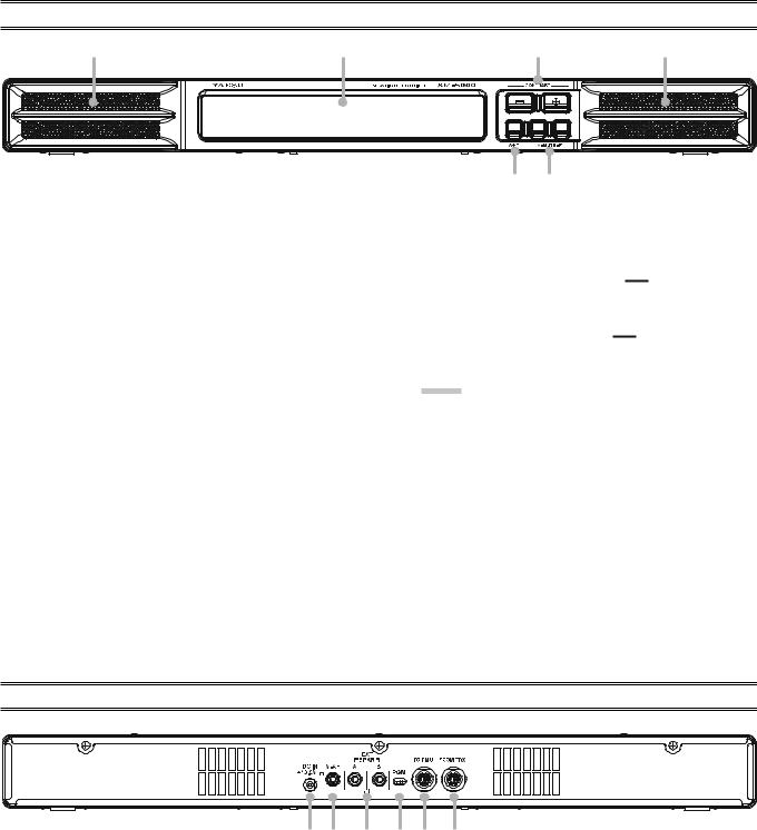
FRONT PANEL SWITCHES |
|
|
|
|
|
|
Speaker
Dual 2.6” x 1” (65 x 25 mm) oval speakers direct the sound toward the front. The audio response is specially tailored for shortwave reception.
Independent Left or Right mute capability is provided for VFO-Aand VFO-B on the Station Monitor, without changing any settings on the transceiver.
Display
This LCD Monitor displays the Spectrum Scope of VFO- A band activity.
[CONTRAST]([+] / [–]) Switch
These switches are used for adjustment of the LCD Contrast Setting and the Audio Setting.
Press both switches simultaneously, to toggle the adjustment mode between “LCD Contrast Setting” and “Audio Setting”.
Refer to page 6 for the details of the “Audio Setting”, and refer to page 7 for the details of the “LCD Contrast Setting”.
[A+B] Switch
Selects the speaker output mode during Dual Receive operation.
When this switch is un-pressed (  ), the left speaker produces audio from the VFO-A receiver, while the right speaker produces audio from VFO-B receiver.
When this switch is depressed ( 
 ), mixed audio from the VFO-A and VFO-B receivers is produced by both speakers.
NOTE:
1)Requires FTDX5000 Menu item “108 ROUT HEADPHN” be set to “SEPARATE”.
2)When receiving only VFO-A or VFO-B, the audio is routed to both speakers, regardless of the switch position.
[MUTE-A] / [MUTE-B] Switches
The [MUTE-A] switch allows you to mute the audio from the VFO-A receiver. Similarly, the [MUTE-B] switch allows you to mute the audio from the VFO-B receiver.
This can be particularly useful during Dual Receive operation, when you want to concentrate on just one receiver for a moment.
REAR PANEL CONNECTIONS
|
|
DC IN +13.8V Jack |
[PGM] Switch |
Connect the supplied DC cable between this jack and +13.8V jack on the FTDX5000 transceiver.
V-AF Jack
Connect the supplied connection cable between this jack and V-AF jack on the FTDX5000 transceiver.
EXT SPKR Jacks
Connect the external speakers to these jacks, if desired. Inserting a plug into the A jack disables the left side speaker of the SM-5000. Similarly, inserting a plug into the B jack disables the right side speaker of the SM-5000.
This slide switch is used for updating the SM-5000 firmware. The update software and instructions are available for download from the Vertex Standard website (http:// www.yaesu.com/).
TO DMU Jack
To use the optional DMU-2000 Data Management Unit at the same time, connect the cable supplied with the DMU2000 between this jack and the TRX jack on the DMU2000.
FROM TRX Jack
Connect the supplied control cable between this jack and the DMU jack on the FTDX5000 transceiver.
- 2 -
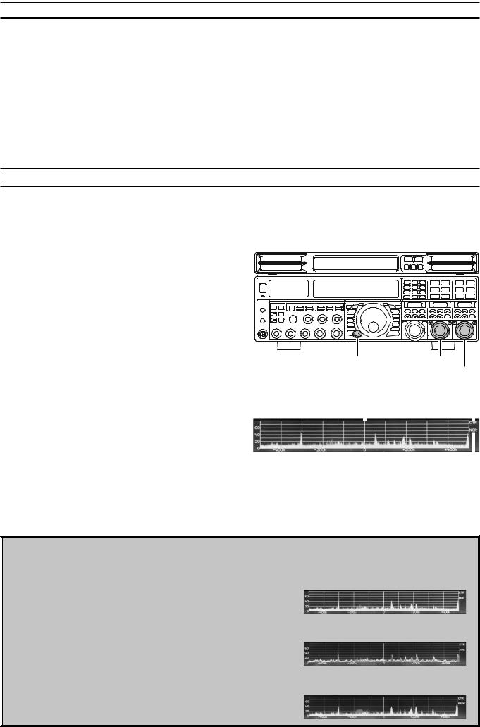
ABOUT THE SPECTRUM SCOPE
The SM-5000 Spectrum Scope provides a visual display of an amateur band segment tuned by the VFO-A receiver. The default bandwidth allows you to see both strong and weak signals clearly depicted on the monitor screen. During transmission, the transmitter’s waveform will be displayed, except when the frequency span is set to 2500 kHz in the CTR (Center) display mode or set to 1000/2500 kHz in the FIX (Fixed) display mode.
The LBWS (Limited Band Width Sweep) function provides very high-speed signal detection over a limited segment of the currently displayed spectrum. The CTR (Center) display mode will let you monitor signals close to your current frequency (your frequency is located at the center of the screen). When the FIX (fixed) mode is engaged, the left band edge frequency is fixed, and your operating frequency may be indicated within the displayed bandwidth. These features have been carefully considered for their utility in actual Amateur Radio operation.
Note: The vertical axis of the Spectrum Scope display is approximately 10 dB per division.
USING THE CTR (CENTER) DISPLAY MODE
In the CTR mode, the operating frequency is shown at the center of the monitor screen. The selected Spectrum Scope frequency bandwidth is displayed across the monitor screen. Signals received on the VFO-A band are shown. (To show signals more clearly and easily, the LBWS (Limited Band Width Sweep) function lets you perform a high-speed, high-resolution sweep of a limited band segment (See page 4 for details).
1.Press and hold the FTDX5000 [C.S] key for 2 seconds to to engage the Scope Menu mode.
The SUB DISPLAY-I window will show the Group name (SCOPE), while the SUB DISPLAY-II window will show the Menu item. The SUB DISPLAY-III window shows the setting of the currently-selected Menu item.
2.Rotate the (VFO-A)[SELECT] knob to select the Menu item “MODE”.
3.Rotate the (VFO-B)[SELECT] knob to select “CENTER”. The current VFO-A frequency is displayed at the center of the screen.
4.Rotate the (VFO-A)[SELECT] knob to select the Menu item “SPAN”, then rotate the (VFO-B)[SELECT] knob to select the desired frequency span to monitor.
Available selections are: 25 kHz, 50 kHz, 100 kHz, 250 kHz, 500 kHz, 1000 kHz, and 2500 kHz.
5.Rotate the (VFO-A)[SELECT] knob to select the Menu item “ATT”, then rotate the (VFO-B)[SELECT] knob to select the display attenuation value according to current propagation conditions, your operating frequency, and antenna, etc. Available selections are: 0 dB, 10 dB, and 20 dB.
6.Press the [C.S] key briefly to save the new setting and exit to normal operation.
[C.S] Switch (VFO-A)[SELECT] Knob
|
|
(VFO-B)[SELECT] Knob |
|
|
|
OPERATING Mode |
|
Current VFO-A Frequency |
CTR |
||
|
|
|
|
|
|
|
|
|
|
|
|
|
|
|
|
TRACE Mode
NOR: Normal
AVG: Average
PEAK: Peak Hold
CHANGING THE TRACE MODE
1. Press and hold the FTDX5000 [C.S] key for 2 sec- |
NORMAL: The real-time signal strength will be displayed. |
||
onds to engage the Scope Menu mode. |
Normally, you will want to use this mode. |
||
The SUB DISPLAY-I window will show the Group |
|
|
|
|
|
||
name (SCOPE), while the SUB DISPLAY-II window |
|
|
|
will show the Menu item. The SUB DISPLAY-III win- |
|
|
|
AVERAGE: The averaged signal strength will be dis- |
|||
dow shows the setting of the currently-selected Menu |
played. |
||
|
|||
item. |
|
|
|
|
|
||
2. Rotate the (VFO-A)[SELECT] knob to select the |
|
|
|
Menu item “TRACE”, then rotate the (VFO- |
|
|
|
PEAKHOLD: The Peak signal level will be displayed and |
|||
B)[SELECT] knob to select the desired trace mode. |
|||
held until the frequency is changed. |
|||
Available selections are shown at the right. |
|||
|
|
||
3. Press the [C.S] key briefly to save the new setting and |
|
|
|
exit to normal operation. |
|
|
|
-3-
 Loading...