


GS-232A
GS-232A
Computer Control Interface
for Antenna Rotators
YAESU MUSEN CO., LTD.
4-8-8 Nakameguro, Meguro-Ku, Tokyo 153-8644, Japan
YAESU U.S.A.
17210 Edwards Rd., Cerritos, CA 90703, U.S.A.
YAESU EUROPE B.V.
P.O. Box 75525 1118 ZN, Schiphol, The Netherlands
YAESU UK LTD.
Unit 12, Sun Valley Business Park, Winnall Close
Winchester, Hampshire, SO23 0LB, U.K.
YAESU GERMANY GmbH
Am Kronberger Hang 2, D-65824 Schwalbach, Germany
YAESU HK LTD.
11th Floor Tsim Sha Tsui Centre, 66 Mody Rd.,
Tsim Sha Tsui East, Kowloon, Hong Kong

GS-232A Computer Control Interface
for Yaesu Antenna Rotators
The GS-232A provide digital control of most models of
Yaesu antenna rotatorsø from the serial port of an external
personal computer.
The GS-232A contains its own microprocessor with ROM
and RAM (memory), and a l0-bit analog-to-digital (A-D)
converter. The 3-wire async serial line can be configured for
serial data rates from 150 to 9600 baud. The GS-232A has a
DB-9 “male” connector for connection to the (RS-232C)
COM port of your computer. Purchase or construnct a
“straight” type serial cable, ensuring it has the correct gender and number of pins for connection to your system.
Firmware on the GS-232A supports either direct keyboard
control, or commands from programs written specifically to
support it (software is not supplied by Yaesu). In addition
to reading and setting antenna angle and rotation speed,
the firmware includes clocked positioning routines to auto-
matically step the antenna through up to 3800 angles at
programmable intervals, such as for tracking band openings or satellites (with an elevation rotator).
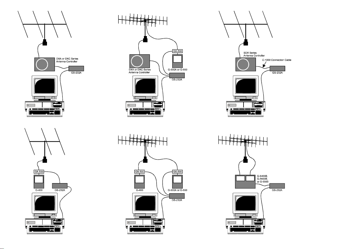
Please read this manual carefully to install the GS-232A. If
also installing a G-400, G-500A or G-550 with the GX-500
Automatic Control Adapter, follow the procedures in the
GX-500 manual before installing the GS-232A .
ø
G-800DXA/G-1000DXA/G-2800DXA
G-800DXC/G-1000DXC/G-2800DXC
G-400
Azimuth Rotator,
G-500A/G-550
G-5400B/G-5600B/G-5500
above Azimuth and Elevation rotator combination.
G-400
Azimuth Rotator and
one
GX-500
Elevation Rotator,
AZ-EL Rotator, and
G-500A/G-550
Automatic Control Adapter each.
Azimuth Rotator,
Azimuth Rotator,
Elevation Rotator requires
GENERAL DESCRIPTION
1

GENERAL
Power Requirements: DC 12 V, 110 mA
Case Size: 110 (W) x 21 (H) x 138 (D) mm
Weight (approx.): 380 g
Semiconductors
Microprocessor: HD6303XP
ROM: 27C64
RAM: 6264
SPECIFICATIONS
A/D Converter: HD46508PA (10 bits)
Serial Comms: 3-wire Async. DCE
RS-232C voltage levels,
150 to 9600 baud, 8 data bits,
1 stop bit, no parity, no handshake
CONNECTOR PINOUTS
Serial I/O:
9-pin DB-9 connector (RS-232C connector)
Pin 2 - Tx Data
Pin 3 - Rx Data
Pin 5 - Signal Ground
Rotator Control:
5-pin connector (EL connector)
Pin 1 - UP switch (open collector)
Pin 2 - DOWN switch (open collector)
Pin 3 - analog output (0.5 - 4.5 V, four steps)
Pin 4 - analog input (0-5V elevation)
Pin 5 - analog ground
5-pin connector (AZ connector)
Pin 1 - RIGHT switch (open collector)
Pin 2 - LEFT switch (open collector)
Pin 3 - analog output (0.5 - 4.5 V, four steps)
Pin 4 - analog input (0-5V azimuth)
Pin 5 - analog ground
2

SUPPLIED ACCESSORIES
r Control cable for the Azimuth Rotatorø1................1 pc
(“5-pin” 1 “Min-DIN” cable)
r Control cable for the AZ/EL Rotatorø2....................1 pc
(“Dual 5-pin” 1 “DIN” cable)
r DC cable w/coaxial plug.........................................1 pc
r Hook & loop fasteners (for mounting)...................1 pc
ø1: G-5400B-G-5600B/G-5500
ø2: G-800DXA/G-1000DXA/G-2800DXA &
G-800DXC/G-1000DXC/G-2800DXC
AVAILABLE OPTIONS
GX-500
C-1000 Connection Cable
NC-72B/C/F/U
(
GS-232A version
ø3:“B” suffix is for use with 117 VAC,
)
Control Adapter
(Check with your dealer)
(for SDX series Azuimuth Rotator)
ø3
AC Adapter
“C” suffix is for use with 220-240 VAC,
“F” suffix is for use with 220 VAC, or
“U” suffix is for use with 230 VAC
ACCESSORIES & OPTION
3
During installation, a personal computer with a serial port
and terminal software is required to calibrate trimmers on
the Controller and on the Control Interface. Any simple interactive terminal program can be used - it only has to transmit keystrokes as typed, and display characters received
from the GS-232A.
INSTALLATION
POWER & CONTROL CONNECTIONS
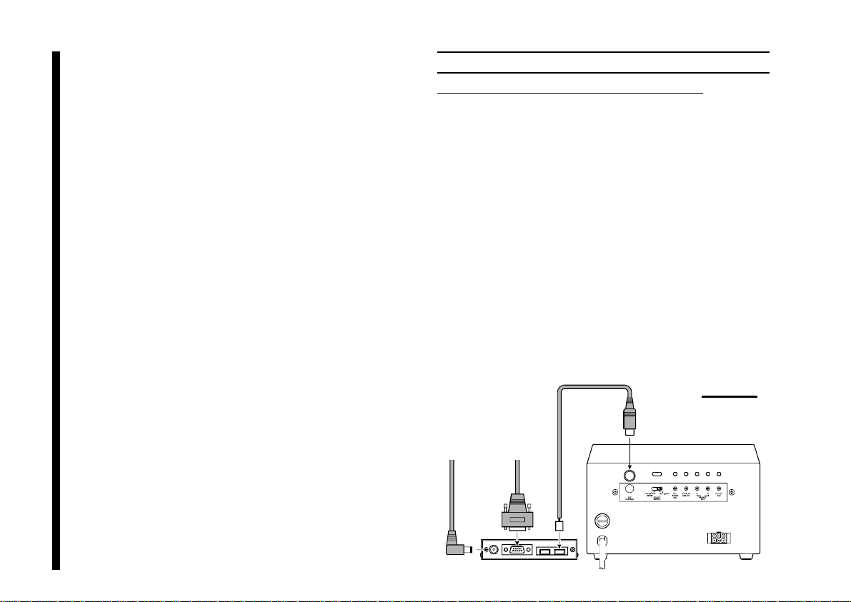
DXA or DXC Series Azimuth Rotator
Connect the supplied DC cable to a source of 12 VDC.
r
The red lead connects to the Positive (+) DC terminal,
and the black lead connects to the Negative
(–) DC terminal. The GS-232A requires 110 mA. The
supplied cable has a 500-mA fast-blow fuse. Use only
the same type fuse for replacement.
Plug the coaxial power connector into the DC 12V jack
r
on the GS-232A rear panel.
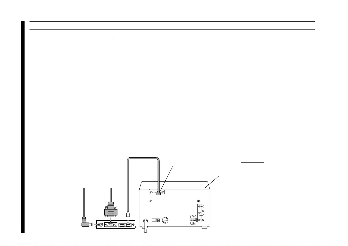
Connect the supplied Control cable (“5-pin” 1 “Mini-
r
DIN”) between the EXT CONTROL connector on the
rotator’s controller and AZ connector on the rear panel
of the GS-232A (Figure 1).
Figure 1
DXA or DXC series
Azimuth Rotator
To DC 12V Power Source
To Serial port of the computer
4
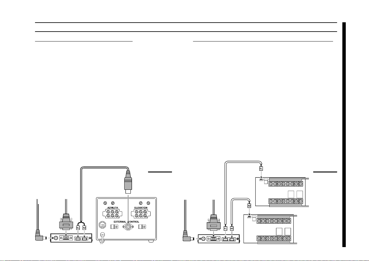
POWER & CONTROL CONNECTIONS
G-5400B/-5600B Az-EL Rotator
Connect the supplied DC cable to a source of 12 VDC.
r
The red lead connects to the Positive (+) DC terminal,
and the black lead connects to the Negative
(–) DC terminal. The
supplied cable has a 500-mA fast-blow fuse. Use only
the same type fuse for replacement.
Plug the coaxial power connector into the DC 12V jack
r
on the GS-232A rear panel.
Connect the supplied Control cable (“Dual 5-pin”
r
“DIN”) between the rotator’s controller and GS-232A.
Be careful to match the “AZ” and “EL” labels on the cable
with the same labels on the rear panel of the GS-232A
(Figure 2).
GS-232A requires 110 mA. The
G-400/G-500 or G-400/G-550 & pair of GX-500
Connect the supplied DC cable to a source of 12 VDC.
r
The red lead connects to the Positive (+) DC terminal,
and the black lead connects to the Negative
(–) DC terminal. The GS-232A requires 110 mA. The
supplied cable has a 500-mA fast-blow fuse. Use only
the same type fuse for replacement.
Plug the coaxial power connector into the DC 12V jack
r
on the GS-232A rear panel.
1
Connect the 5-pin to 5-pin cable (supplied with the GX-
r
500; requires two sets) between the GX-500(s) and GS232A (Figure 3).
INSTALLATION
To DC 12V Power Source
To Serial port
of the computer
Figure 2
G-5400B/-5600B
or G-5500
AZ/EL Rotator
To DC 12V Power Source
To Serial port of the computer
GX-500
GX-500
To Elevation
To Elevation
To Azimuth Controller
To Azimuth Rotator
Figure 3
Controller
Rotator
5
SDX Series Azimuth Rotator
Prepare the optional C-1000 Connection Cable.
r
Remove the Top cover from the controller.
r
Connect the 8-pin connector of the C-1000 Connection
r
cable to the exposed 8-pin connector located the rear
left corner in the controller.
Route the 5-pin connector of the C-1000 Connection
r
INSTALLATION
cable through out the rubber grommet on the rear panel
of the controller, and connect it to the AZ connector on
the rear panel of the GS-232A (Figure 4).
Replace the Top Cover.
r
POWER & CONTROL CONNECTIONS
Connect the supplied DC cable to a source of 12 VDC.
r
The red lead connects to the Positive (+) DC terminal,
and the black lead connects to the Negative
(–) DC terminal. The GS-232A requires 110 mA. The
supplied cable has a 500-mA fast-blow fuse. Use only
the same type fuse for replacement.
Plug the coaxial power connector into the DC 12V jack
r
on the GS-232A rear panel.
6
To DC 12V Power Source
To Serial port of the computer
Optional C-1000 Connection Cable
Output Grommet for
C-1000 Connection Cable
SDX series
Azimuth Rotator
Figure 4
Exposed 8-pin Connector
(Inside of the Controller)
 Loading...