


50/144/430 MHz
TRIPLE-BAND HEAVY DUTY SUBMERSIBLE TRANSCEIVER
OPERATING MANUAL
VERTEX STANDARD CO., LTD.
4-8-8 Nakameguro, Meguro-Ku, Tokyo 153-8644, Japan
VERTEX STANDARD
US Headquarters
17210 Edwards Rd., Cerritos, CA 90703, U.S.A.
International Division
8350 N.W. 52nd Terrace, Suite 201, Miami, FL 33166, U.S.A.
YAESU EUROPE B.V.
P.O. Box 75525, 1118 ZN Schiphol, The Netherlands
YAESU UK LTD.
Unit 12, Sun Valley Business Park, Winnall Close
Winchester, Hampshire, SO23 0LB, U.K.
VERTEX STANDARD HK LTD.
Unit 5, 20/F., Seaview Centre, 139-141 Hoi Bun Road, Kwun Tong, Kowloon, Hong Kong

Contents
Introduction ..................................................................... |
1 |
Controls & Connections ................................................. |
2 |
Display Icons & Indicators ............................................ |
3 |
Keypad Function ............................................................ |
4 |
Accessories & Options ................................................... |
6 |
Installation of Accessories ............................................. |
7 |
Antenna Installation ..................................................... |
7 |
How to Install the Quick Draw Belt Clip ................... |
8 |
Installation of FNB-80LI Battery Pack ....................... |
8 |
Installation of FBA-23 (option) |
|
Alkaline Battery Case ............................................. |
9 |
Battery Life Information ............................................ |
10 |
AC Operation Using NC-72 ..................................... |
10 |
Interface of Packet TNCs ............................................ |
11 |
Operation ....................................................................... |
12 |
Switching Power On and Off .................................... |
12 |
Adjusting the Volume Level ..................................... |
12 |
Squelch Adjustment ................................................... |
13 |
Selecting the Operating Band .................................... |
14 |
Selecting the Frequency Band ................................... |
15 |
Frequency Navigation ................................................ |
16 |
Audio Muting ............................................................. |
17 |
BAND Link ................................................................ |
17 |
Transmission .............................................................. |
17 |
Changing the Transmitter Power Level ............... |
18 |
VOX Operation ......................................................... |
19 |
AM Broadcast Reception .......................................... |
20 |
AM Aircraft Reception .............................................. |
20 |
FM Broadcast/TV Audio Reception ......................... |
21 |
Weather Broadcast Reception .................................. |
22 |
Keyboard Locking ..................................................... |
23 |
Keypad/LCD Illumination ......................................... |
24 |
Disabling the Keypad Beeper ................................... |
24 |
Advanced Operation .................................................... |
25 |
Setting the Frequency Display Image Size ............... |
25 |
Changing the Channel Steps ..................................... |
25 |
Changing the Operating Mode .................................. |
26 |
Repeater Operation .................................................... |
27 |
CTCSS Operation ...................................................... |
30 |
DCS Operation .......................................................... |
31 |
Tone Search Scanning ............................................... |
32 |
CTCSS/DCS Bell Operation ..................................... |
33 |
Split Tone Operation ................................................. |
33 |
Tone Calling (1750 Hz) ............................................ |
34 |
ARTS (Automatic Range Transponder System) ...... |
35 |
DTMF Operation ....................................................... |
38 |
Emergency Channel Operation ................................. |
39 |
ATT (Front End Attenuator) ..................................... |
40 |
Receive Battery Saver Setup ..................................... |
40 |
TX Battery Saver ....................................................... |
41 |
Disabling the “STROBE” ......................................... |
41 |
Automatic Power-Off (APO) Feature ....................... |
42 |
Transmitter Time-Out Timer (TOT) ......................... |
42 |
Busy Channel Lock-Out (BCLO) ............................. |
43 |
MIC Monitor ............................................................. |
43 |
Changing the TX Deviation Level ............................ |
44 |
Memory Mode .............................................................. |
45 |
Regular Memory Operation ...................................... |
46 |
Memory Storage ................................................... |
46 |
Storing Independent Transmit Frequencies |
|
(“Odd Split”) ........................................................ |
46 |
Memory Recall ..................................................... |
47 |
HOME Channel Memory ..................................... |
47 |
Labeling Memories ............................................... |
48 |
Memory Offset Tuning ......................................... |
49 |
Masking Memories ............................................... |
50 |
Memory Group Operation ................................... |
51 |
Moving Memory Data to the VFO ...................... |
52 |
Memory Only Mode ............................................. |
52 |
Hyper Memory Operation ......................................... |
53 |
One-Touch Memory Operation ................................ |
54 |
Sort-wave Broadcast Station Memory Channels ..... |
55 |
VHF Marine Memory Channels ............................... |
56 |
Scanning ......................................................................... |
57 |
VFO Scanning ........................................................... |
58 |
Memory Scanning ...................................................... |
58 |
Temporary Memory Skip ..................................... |
59 |
How to Skip (Omit) a Channel |
|
During Memory Scan Operation .......................... |
59 |
Preferential Memory Scan .................................... |
60 |
Programmable (Band Limit) Memory Scan (PMS) . 61 |
|
“Priority Channel” Scanning (Dual Watch) ............. |
61 |
Automatic Lamp Illumination on Scan Stop ............ |
62 |
Band Edge Beeper ..................................................... |
62 |
Spectrum Analyzer Operation ................................... |
63 |
Smart Search Operation ............................................ |
64 |
Channel Counter Operation ...................................... |
66 |
Internet Connection Feature ...................................... |
67 |
Sensor Mode .................................................................. |
68 |
Sensor Mode Option ................................................. |
69 |
Clock Set .............................................................. |
69 |
Selecting the Wave Form Display ....................... |
70 |
Selecting the Unit of Temperature Display ......... |
70 |
Selecting the Unit of |
|
Atmospheric Pressure Meter (Barometer) ........... |
70 |
Correcting the Atmospheric Pressure Meter |
|
(Barometer Offset) ............................................... |
70 |
Selecting the Unit of Altimeter ............................ |
71 |
Correcting the Altimeter Setting |
|
(Altimeter Offset) ................................................. |
71 |
Timer Operation ........................................................... |
72 |
Display Customization ................................................. |
73 |
Icon Mode .................................................................. |
73 |
Icon Selection ............................................................ |
73 |
Icon Editor ................................................................. |
74 |
Power-Off Display Mode .......................................... |
75 |
S-and TX Power Meter Symbols .............................. |
76 |
Font Editor ................................................................. |
77 |
Display Contrast ........................................................ |
78 |
Display Dimmer ......................................................... |
78 |
STROBE Customization ........................................... |
79 |
Reset Procedures .......................................................... |
80 |
Cloning ........................................................................... |
81 |
Set Mode ........................................................................ |
82 |
Installation of the SU-1 ................................................ |
97 |
Specifications ................................................................. |
98 |
Appendix ...................................................................... |
100 |
INTRODUCTION
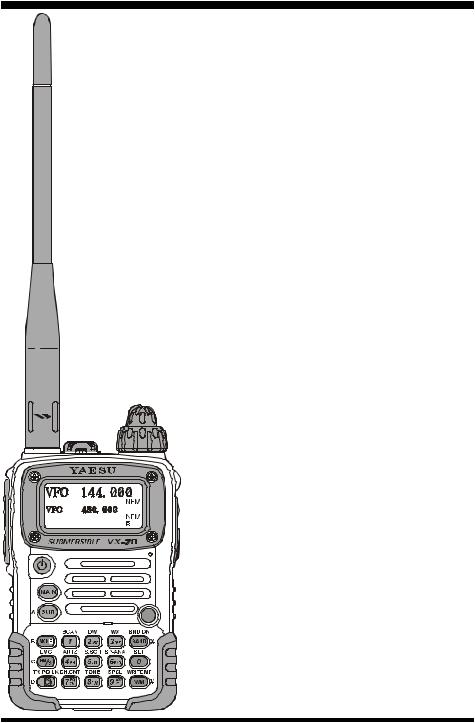
The VX-7R is a miniature 3-band FM transceiver with extensive receive frequency coverage, providing leading-edge features for VHF and UHF twoway amateur communications, along with unmatched monitoring capability.
The VX-7R’s small size allows you to take it anywhere – hiking, skiing, or while walking around town
– and its operating flexibility brings the user many avenues of operating enjoyment. Besides 50, 144, and 430 MHz transceive operation, the VX-7R provides 222 MHz QRP (0.3 Watts) transceive operation, receive coverage of the AM (MF) and FM broadcast bands, HF Shortwave Bands up to 16 MHz, VHF and UHF TV bands, the VHF AM aircraft band, and a wide range of commercial and public safety frequencies! Dual In-band Receive (V/V and U/U) lets you keep track of two active frequencies. And the optional Barometer pressure Sensor Unit provides readout of barometric pressure and altitude while mountain climbing or hiking, and it also generates a Weather Forecast based on measured data.
The transmitter section provides 5 Watts of clean power output on the FM operation on the 50 MHz, 144 MHz, and 430 MHz bands with the supplied FNB-80LI Battery Pack, and 0.3 Watts output on 222 MHz, and 1 Watt of carrier output for AM operation on 50 MHz. Both CTCSS and DCS tone signaling formats are built into the VX-7R, in addition to Yaesu’s exclusive ARTSTM-(Auto-Range Transponder System), which “beeps” the user when you move out of communications range with another ARTSTM-equipped station.
We appreciate your purchase of the VX-7R, and encourage you to read this manual thoroughly, so as to learn about the many exciting features of your exciting new Yaesu hand-held transceiver!
VX-7R OPERATING MANUAL |
1 |

CONTROLS & CONNECTIONS
ANTENNA
Connect the supplied rubber flex antenna (or another antenna presenting a 50-Ohm impedance) here.
PTT
(“Push To Talk”) Press this switch inward to transmit, and release it (to receive) after your t r a n s m i s s i o n i s completed.
MONI
Pressing this key disables the noise squelching action, allowing you to hear very weak signals near the background noise level.
 (PWR) Switch
Press and hold this switch for 2 seconds to toggle the transceiver’s power on and off.
|
MIC/SP |
|
|
|
|
DIAL |
|
|
|
|
|
|
|
|
|
|
|
|
This four-conductor |
The main tuning |
|
|
|
|
|
|
|
|
|
|
|
||||||
miniature jack pro- |
Dial is used for set- |
|
|
|
|
|
|
|
|
|
|
|
||||||
|
|
|
|
VOLUME |
||||||||||||||
|
|
|
|
|
|
|
|
|
||||||||||
vides connection |
ting the operating |
This control adjusts |
||||||||||||||||
points for micro- |
frequency, and also |
the audio volume |
||||||||||||||||
phone audio, ear- |
is used for Menu |
level. Clockwise ro- |
||||||||||||||||
phone audio, PTT, |
s e l e c t i o n s a n d |
tation increases the |
||||||||||||||||
and ground. |
other adjustments. |
volume level. |
||||||||||||||||
|
|
|
|
|
|
|
|
|
|
|
|
|
|
|
|
|
|
|
|
|
|
|
|
|
|
|
|
|
|
|
EXT DC |
||||||
|
|
|
|
|
|
|
|
This coaxial DC |
||||||||||
|
|
|
|
|
|
|
|
jack allows connec- |
||||||||||
|
|
|
|
|
|
|
|
tion to an external |
||||||||||
|
|
|
|
|
|
|
|
DC power source |
||||||||||
|
|
|
|
|
|
|
|
(10-16V DC). The |
||||||||||
|
|
|
|
|
|
|
|
center pin of this |
||||||||||
|
|
|
|
|
|
|
|
jack is the Positive |
||||||||||
|
|
|
|
|
|
|
|
(+) line. |
||||||||||
|
|
|
|
|
|
|
|
|
|
|
|
|
|
|
|
|
||
|
|
|
|
|
|
|
|
|
|
|
|
|
MIC |
|||||
|
|
|
|
|
|
|
|
The internal micro- |
||||||||||
|
|
|
|
|
|
|
|
phone is located at |
||||||||||
|
|
|
|
|
|
|
|
the bottom right- |
||||||||||
|
|
|
|
|
|
|
|
hand corner of the |
||||||||||
|
|
|
|
|
|
|
|
display. |
||||||||||
|
|
|
|
|
|
|
|
|
|
|
|
|||||||
|
|
|
|
|
|
|
|
|
|
SPEAKER |
||||||||
|
|
|
|
|
|
|
|
T h e i n t e r n a l |
||||||||||
|
|
|
|
|
|
|
|
speaker is located |
||||||||||
|
|
|
|
|
|
|
|
directly below the |
||||||||||
|
|
|
|
|
|
|
|
display. |
||||||||||
|
|
|
|
|
|
|
|
|
|
|
|
|
|
|
||||
|
|
|
|
|
|
|
|
|
|
|
|
STROBE |
||||||
|
|
|
|
|
|
|
|
The STROBE is |
||||||||||
|
|
|
|
|
|
|
|
the unique indica- |
||||||||||
|
|
|
|
|
|
|
|
tor which indicates |
||||||||||
|
|
|
|
|
|
|
|
the transceiver’s |
||||||||||
|
|
|
|
|
status. |
|||||||||||||
|
|
|
KEYBOARD |
|||||||||||||||
These 17 keys select many of the |
You may customize |
|||||||||||||||||
most important operating features |
the STROBE color |
|||||||||||||||||
on the VX-7R. |
|
|
|
|
setup via the Menu |
|||||||||||||
This function of the keys are de- |
mode. |
|||||||||||||||||
scribed in details on pages 4 and 5. |
|
|
|
|
|
|
|
|
|
|
|
|||||||
2 |
VX-7R OPERATING MANUAL |
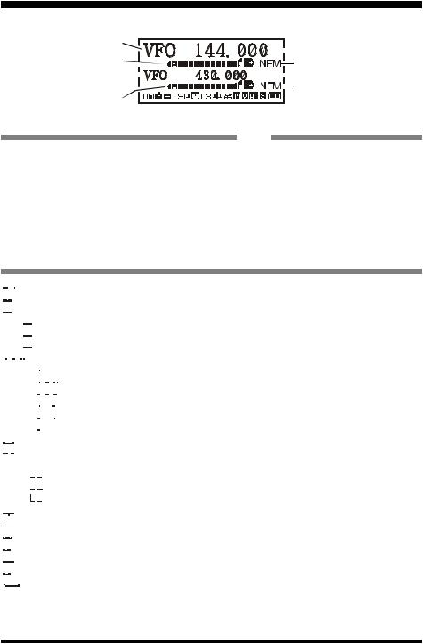
DISPLAY ICONS & INDICATORS
“Main” Band |
|
|
Frequency Control |
“Main” Band Frequency |
|
“Main” Band S- & PO Meter |
||
“Main” Band Operating Mode |
||
|
||
“Sub” Band |
“Sub” Band Frequency |
|
Frequency Control |
“Sub” Band Operating Mode |
|
“Sub” Band S- & PO Meter |
|
|
FREQUENCY CONTROL |
OPERATING MODE |
|
VFO: VFO Mode (page 15) |
NFM: FM |
|
MR: Memory Mode (page 45) |
WFM: Wide FM |
|
MT: Memory Tume Mode (page 49) |
AM: AM |
|
PMS: Programable Memory Scan Mode (page 61) |
|
|
WX: Weather Channel (page 22) |
|
|
Sea: Marine Channel (page 56) |
|
|
HYP: Hyper Memoy Mode (page 53) |
|
|
OTM: One Touch Memory Mode (page 54) |
|
|
LST: Short-wave Broadcast StationMemory (page 55) |
|
ICON


 : Dual Watch Active (page 61)


 : Key Lock Active (page 23)


 : Repeater Shift Direction (page 27)


 : Minus (–) Shift


 : Plus (+) Shifh

 : Odd Splits


 : CTCSS/DCS Operation (page 30)

 : Tone Encoder


 : Tone Squelch


 : Digital Code Squelch (DCS)


 : TX: Tone Encoder, RX: DCS Decoder


 : TX: DCS Encoder, RX: Tone Decoder

 : DCS Encoder


 : Automatic Power-Off Active (page 42)


 : Low TX Power Selected (page 18)
No Icon: High Power


 : Low Power 3


 : Low Power 2
 : Low Power 1


 : Bell Alarm Active (page 33)


 : DTMF Autodialer Active (page 39)


 : Audio Mute Active (page 17)

 : VOX Active (page 18)


 : RF Front-end Attenuator Active (page 40)

 : Battery Saver Active (page 40)


 : Low Battery! (page 10)
VX-7R OPERATING MANUAL |
3 |
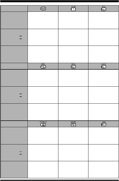
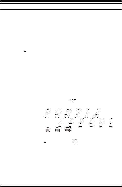
KEYPAD FUNCTIONS
Press Key
Press + 
Press and Hold
Key
Press Key
Press + 
Press and Hold
Key
Press Key
Press + 
Press and Hold
Key
Activates the “Alternate” key Function
No Action
Activates the “Memory Write” mode (for memory channel storage)
Reverses the transmit and receive frequencies while working through a repeater
Switches operation to the “Home” (favorite frequency) Channel
Activates the
EMERGENCY Function
Activates the
Internet Connection
Feature
Select the desired transmit power output
Activates the
Key Lock Feature
Frequency entry |
Frequency entry |
|
digit “1” |
digit “2” |
|
Activates the Scanner |
Activates the |
|
Dual Watch Feature |
||
|
||
Store the current setting |
Store the current setting |
|
into the |
into the |
|
Hyper Memory “1” |
Hyper Memory “2” |
Frequency entry |
Frequency entry |
|
digit “4” |
digit “5” |
|
Activates the |
Activates the |
|
Smart SearchTM |
||
ARTS Feature |
||
Feature |
||
|
||
Store the current setting |
Store the current setting |
|
into the |
into the |
|
Hyper Memory “4” |
Hyper Memory “5” |
Frequency entry |
Frequency entry |
digit “7” |
digit “8” |
Activates the |
Activates the |
Channel Counter |
CTCSS or DCS |
Feature |
Operation |
Store the current setting |
Store the current setting |
into the |
into the |
Hyper Memory “7” |
Hyper Memory “8” |
4 |
VX-7R OPERATING MANUAL |
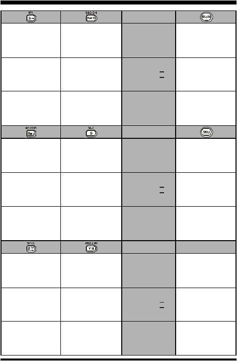
KEYPAD FUNCTIONS
Frequency entry digit “3”
Recall the “Weather” broadcast channel bank
Store the current setting into the
Hyper Memory “3”
Frequency entry digit “6”
Activates the
Spectrum Analyzer
(Spectra-ScopeTM)
Feature
Store the current setting into the
Hyper Memory “6”
Frequency entry digit “9”
Enters the
“Special Memory”
mode
Moves operation to the next-highest frequency band
Moves operation to the next-lowest frequency band
Moves operation to the next-highest frequency band
Frequency entry digit “0”
Enter the “Set”
(Menu) Mode
Store the current setting into the
Hyper Memory “0”
Switches frequency control between the VFO and Memory System
No Action
Press Key
Press + 
Press and Hold
Key
Press Key
Press + 
Press and Hold
Key
Press Key
Press + 
Switches the “Upper”
frequency to be the
“Operating” (TX) Band
Switches the “Upper” frequency display between the
“Large Character” and “Small Character” mode
Activates the
Dual Receive Feature
Switches the “Lower”
frequency to be the
“Operating” (TX) Band
Switches the “Lower” frequency display between the
“Large Character” and “Small Character” mode
Activates the
Dual Receive Feature
MONI Key
USA Version:
Disables the Noise and
Tone Squelch System
EXP Version:
Activates T.CALL (1750 Hz)
for repeater access
USA Version: Enters the Squelch level
setting mode
EXP Version:
Activates T.CALL (1750 Hz) for repeater access
Store the current setting |
Activates the |
|
“Memory Tune” mode |
||
into the |
||
while in the |
||
Hyper Memory “9” |
||
Memory Recall mode |
||
|
Press and Hold
No Action
Key
VX-7R OPERATING MANUAL |
5 |
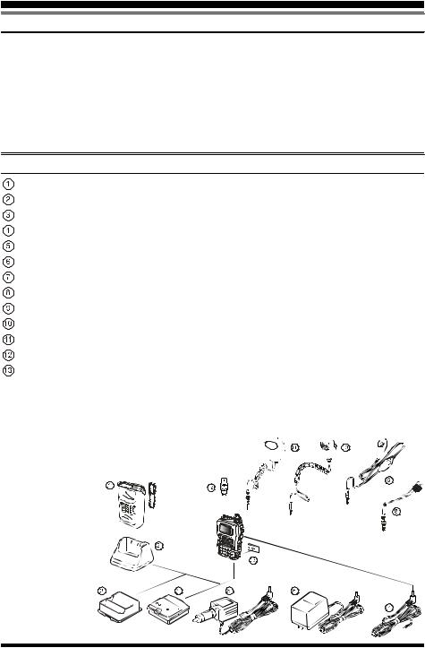
ACCESSORIES & OPTIONS
ACCESSORIES SUPPLIED WITH THE VX-7R
FNB-80LI Battery Pack (7.4V/1,300mAh)
NC-72B/C Battery Charger
Quick Draw Belt Clip
Hand Strap
Antenna
Operating Manual
Warranty Card
|
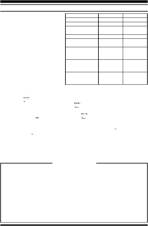
AVAILABLE OPTIONS FOR YOUR VX-7R |
CSC-88 |
Soft Case |
CD-15A |
Rapid Charger (requires NC-72B/C) |
FBA-23 |
2 x “AA” Cell Battery Case (batteries not supplied) |
FNB-80LI |
Battery Pack (7.4V/1,300 mAh) |
E-DC-5B |
DC Cable w/Noise Filter |
NC-72B/C |
Battery Charger |
E-DC-6 |
DC Cable; plug and wire only |
CT-91 |
Microphone Adapter |
VC-27 |
Earpiece/Microphone |
MH-57A4B |
Speaker/Microphone |
CMP460A |
Waterproof Speaker/Microphone |
CN-3 |
BNC-to-SMA Adapter |
SU-1 |
Barometric Pressure Sensor Unit |
Availability of accessories may vary. Some accessories are supplied as standard per local requirements, while others may be unavailable in some regions. Consult your Yaesu Dealer for details regarding these and any newly-available options. Connection of any non-Yaesu- approved accessory, should it cause damage, may 


 void the Limited Warranty on this apparatus.


6 |
VX-7R OPERATING MANUAL |
INSTALLATION OF ACCESSORIES
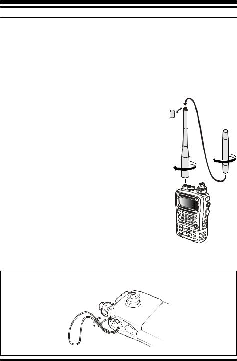
ANTENNA INSTALLATION
The supplied antenna provides good results over the entire frequency range of the transceiver. However, for enhanced base station medium-wave and shortwave reception, you may wish to connect an external (outside) antenna.
The supplied antenna consists of two sections: the “Base Antenna” (used for operation above 50 MHz), and the “Extender Element” (used for monitoring of frequencies below 50 MHz).
To install the supplied antenna
Hold the bottom end of the antenna, then screw it onto the mating connector on the transceiver until it is snug. Do not overtighten by use of extreme force.
When operating the VX-7R on the 50 MHz band and lower frequencies, disconnect the antenna cap from the base antenna, then screw the Extender Element onto the Antenna Base. Of course, the VX-7R may be operated on frequencies higher than the 50 MHz band while the Extender Element is still attached onto the Antenna Base.
Notes:
¦ Never transmit without having an antenna connected.
¦ When installing the supplied antenna, never hold the upper part of the antenna while screwing it onto the mating connector on the transceiver.
¦ If using an external antenna for transmission, ensure that the SWR presented to the transceiver is 1.5:1 or lower.
¦ Take care not lose the antenna cap when removing it from the Base Antenna.
HAND STRAP INSTALLATION
VX-7R OPERATING MANUAL |
7 |
INSTALLATION OF ACCESSORIES
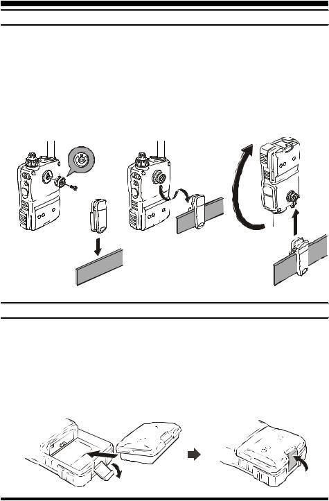
HOW TO INSTALL THE QUICK DRAW BELT CLIP
1.Connect the hanger to the rear of the VX-7R, with the notch pointing directly up, using the supplied screw (Figure 1). Use only the screw included with the clip to mount the clip to the back of the VX-7R!
2.Clip the Quick-Draw Belt Clip onto your belt (Figure 2).
3.To install the VX-7R into the Quick-Draw Belt Clip, align the hanger with the QuickDraw Belt Clip, and slide the VX-7R into its slot until a click is heard (Figure 3).
4.To remove the VX-7R from the Quick-Draw Belt Clip, rotate the VX-7R 180 degrees, then slide the VX-7R out from the Quick-Draw Belt Clip (Figure 4).
Figure 1
Figure 3
Figure 4
Figure 2
INSTALLATION OF FNB-80LI BATTERY PACK
The FNB-80LI is a high-performance Lithium-Ion battery providing high capacity in a very compact package. Under normal use, the FNB-80LI may be used for approximately 300 charge cycles, after which operating time may be expected to decrease. If you have an old battery pack which is displaying capacity which has become diminished, you should replace the pack with a new one.
1.Install the FNB-80LI as shown in the illustration.
2.Close the Battery Pack Latch on the bottom of the radio.
8 |
VX-7R OPERATING MANUAL |
INSTALLATION OF ACCESSORIES
INSTALLATION OF FNB-80LI BATTERY PACK
If the battery has never been used, or its charge is depleted, it may be charged by connecting the NC-72B/C Battery Charger, as shown in the illustration, to the EXT DC jack. If only 12 ~ 16 Volt DC power is available, the optional 

E-DC-5B or E-DC-6 DC Adapter (with its cigarette lighter plug) may also be used for charging the battery, as shown in the illustration.
The display will indicate “now charging” while the battery is being charged. When charging is finished, the display will change to indicate “complete” and the STROBE indicator will glow blue.
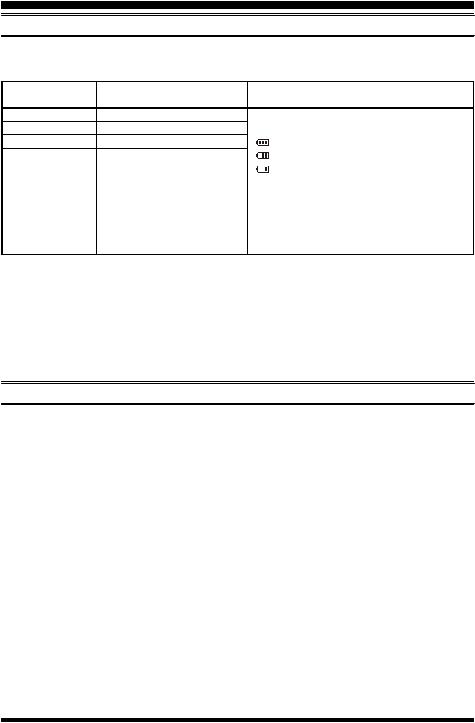
INSTALLATION OF FBA-23 ALKALINE BATTERY CASE (OPTION)
The optional FBA-23 Battery Case allows receive monitoring using two “AA” size Alkaline batteries. Alkaline batteries can also be used for transmission in an emergency, but power output will only be selectable 300 mW and 50 mW, and battery life will be shortened dramatically.
To Install Alkaline Batteries into the FBA-23
1. Slide the batteries into the FBA-23 as shown in the illustration, with the Negative [–] side of the batteries touching the spring connections inside the FBA-23.
2. Open the Battery Pack Latch on the bottom of the radio.
3. Install the FBA-23 as shown in the illustration, with the [+] side facing the bottom of the transceiver.
4. Close the Battery Pack Latch on the bottom of the radio.
The FBA-23 does not provide connections for charging, since Alkaline cells cannot be recharged. Therefore, the NC-72B/C, E-DC-5B, or E-DC-6 may safely be connected to the EXT DC jack when the FBA-23 is installed.
Notes:
¦The FBA-23 is designed for use only with AA-type Alkaline cells.
¦If you do not use the VX-7R for a long time, remove the Alkaline batteries from the FBA-23, as battery leakage could cause damage to the FBA-23 and/or the transceiver.
VX-7R OPERATING MANUAL |
9 |
INSTALLATION OF ACCESSORIES
BATTERY LIFE INFORMATION
When the battery charge is almost depleted, a “Low Voltage” indicator will appear on the display. When this icon appears, it is recommended that you charge the battery soon.
Operating Band |
Battery Life (Approx.) |
Low Voltage Indicator |
|||
FNB-80LI |
FBA-23 |
||||
|
|
|
|||
50 |
MHz (1) |
6.5 hours |
7.0 hours |
FNB-80LI: |
|
144 |
MHz (1) |
6.0 hours |
6.5 hours No Icon: Fully battery power |
||
430 |
MHz (1) |
5.5 hours |
6.0 hours |
: Enough battery power |
|
Other Band (2) |
15 hours |
15 hours |
: Lower battery power |
||
|
|
|
|
: Poor battery power |
|


 : Nearing depletion


 (w/Blink): Prepare to charge the battery
FBA-23:


 : Enough battery power


 (w/Blink): Prepare to replace the battery
(1)TX 6 sec., RX 6 sec. and Squelched 48 sec.
(2)Continuous signal reception
The current battery voltage can be displayed manually on the LCD, by following the instructions on page 68.
Battery capacity may be reduced during extremely cold weather operation. Keeping the radio inside your parka may help preserve the full charge capacity.
AC OPERATION USING NC-72B/C (RECEIVING ONLY)
The VX-7R may be operated from your house current by use of the supplied NC-72B/C Battery Charger. The NC-72B/C should only be used for reception, because it is not capable of supplying sufficient current to support transmission.
To use the NC-72B/C, turn the transceiver off, then plug the miniature connector of the Battery Charger into the EXT DC jack on the side of the radio. Now plug the Battery Charger into the wall outlet. You may now turn on the transceiver.
10 |
VX-7R OPERATING MANUAL |
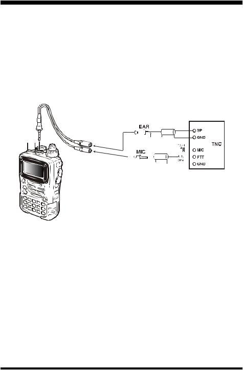
INTERFACE OF PACKET TNCS
The VX-7R may be used for Packet operation, using the optional CT-91 microphone adapter (available from your Yaesu dealer) for easy interconnection to commonly-available connectors wired to your TNC. You may also build your own cable using a four-conductor miniature phone plug, per the diagram below.
The audio level from the receiver to the TNC may be adjusted by using the VOLUME knob, as with voice operation. The input level to the VX-7R from the TNC should be adjusted at the TNC side; the optimum input voltage is approximately 5 mV at 2000 Ohms.
Be sure to turn the transceiver and TNC off before connecting the cables, so as to prevent voltage spikes from possibly damaging your transceiver.
|
|
|
|
|
|
|
|
|
|
|
|
|
|
|
|
|
|
|
|
|
|
|
|
|
|
|
|
|
|
|
|
|
|
|
|
|
|
|
|
|
|
|
|
|
|
|
|
|
|
|
|
|
|
|
|
|
|
|
|
VX-7R OPERATING MANUAL |
11 |
||||||||||
OPERATION
Hi! I’m R. F. Radio, and I’ll be helping you along as you learn the many features of the VX-7R. I know you’re anxious to get on the air, but I encourage you to read the “Operation” section of this manual as thoroughly as
possible, so you’ll get the most out of this fantastic new transceiver. Now. . .let’s get operating!
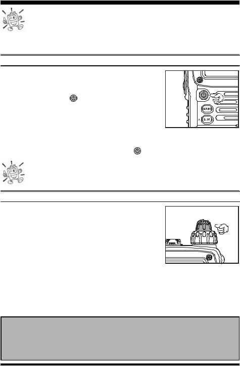
SWITCHING POWER ON AND OFF
1. |
Be sure the battery pack is installed, and that the battery |
||
|
is fully charged. Connect the antenna to the top panel |
||
|
ANTENNA jack. |
(PWR) switch (on the left side |
|
2. |
Press and hold in the |
||
|
of the front panel) for 2 seconds. Two beeps will be heard |
||
|
when the switch has been held long enough, and the open- |
||
|
ing message will appear on the display, then frequency |
||
|
display will appear. After another two seconds, the receive-mode Battery Saver func- |
||
|
tion will become active, unless you have disabled it (see page 40). |
||
3. |
To turn the VX-7R off, press and hold in the |
(PWR) switch again for 2 seconds. |
|
If you don’t hear the two “Beep” tones when the radio comes on, the Beeper may have been disabled via the Menu system. See page 24, which tells you how to reactivate the Beeper.
ADJUSTING THE VOLUME LEVEL
Rotate the VOLUME control (inner knob) to set the desired audio level. Clockwise rotation increases the volume level.
24-hour Clock
The VX-7R has a 24-hour clock with a calendar which covers all dates from January 1, 2000 through December 31, 2099. Set the clock according to the “Clock Set” column on page 69.
12 |
VX-7R OPERATING MANUAL |
OPERATION
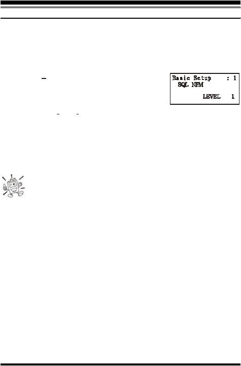
SQUELCH ADJUSTMENT
The VX-7R’s Squelch system allows you to mute the background noise when no signal is being received. Not only does the Squelch system make “standby” operation more pleasant, it also significantly reduces battery current consumption.
The Squelch system may be adjusted independently for the FM and Wide-FM (FM Broadcast) modes.
1. Press the  key, then press the MONI switch on the left side of the radio. This provides a “Short-cut” to Menu Item (Basic Setup #1: SQL NFM) or Menu Item (Basic Setup #2: SQL WFM).
2.Now, press the  or
or  key to set the background noise is just silenced (typically at a setting of about “3” or “4” on the scale); this is point of maximum sensitivity to weak signals.
3.When you are satisfied with the Squelch threshold setting, press the PTT key momentarily to save the new setting and exit to normal operation.
4.You may also adjust the Squelch setting by using the “Set” (Menu) mode. See page 82 for details.
1)The Squelch level may be set on the “Main” and “Sub” bands separately.
2)If you’re operating in an area of high RF pollution, you may need to
consider “Tone Squelch” operation using the built-in CTCSS Decoder. This feature will keep your radio quiet until a call is received from a station sending a carrier which contains a matching (subaudible) CTCSS tone. Or if your friends have radios equipped with DCS (Digital Coded Squelch) like your VX-7R has, try using that mode for silent monitoring of busy channels.
VX-7R OPERATING MANUAL |
13 |
OPERATION
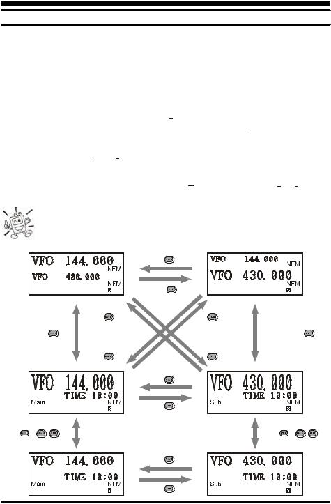
SELECTING THE OPERATING BAND
In the factory default configuration, the VX-7R operates in the “Dual Receive” mode.
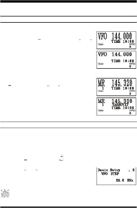
During Dual Receive operation, the “Main” band frequency will be displayed on the upper side of the LCD, and the “Sub” band frequency will be displayed on the lower side, with the “Operating” band (the band on which transmission and band/frequency change are possible) being indicated in large characters, and “Receive only” band being indicated in small characters.
To switch the “Operating” band, press the  key momentarily to engage the “Main” band frequency as the “Operating” band. Alternatively, press the
  key momentarily to engage the “Sub” band frequency as the “Operating” band, described previously.
Press and hold in the  or
or  key for 1/2 seconds to switch to Mono Band Operation with a double-size display.
During Mono band operation, you may press the  key, then press the
  /
/ key, to change the display to show only large characters.
The “Sub” band frequency may only be used on the amateur bands, even if it is designated as the “Operating” band. Extended receiver coverage is only possible on the “Main” band.
|
|
|
Press |
key |
|
|
|
|
|
|
Press |
key |
|
|
|
|
|
|
Press and hold |
Press and hold |
|
|
|
|
|
|
key |
key |
|
|
|
Press and hold |
|
key |
Press and hold |
|
key |
||
|
|
|
Press and hold |
Press and hold |
|
|
|
|
|
|
key |
key |
|
|
|
|
|
|
Press |
key |
|
|
|
|
|
|
Press |
key |
|
|
|
Press |
Æ |
/ |
key |
Press |
Æ |
/ |
key |
|
|
|
Press |
key |
|
|
|
|
|
|
Press |
key |
|
|
|
14 |
VX-7R OPERATING MANUAL |
OPERATION
SELECTING THE FREQUENCY BAND
The VX-7R covers an incredibly wide frequency range, over which a number of different operating modes are used. Therefore, the VX-7R’s frequency coverage has been divided into different operating bands, each of which has its own pre-set channel steps and operating modes. You can change the channel steps and operating modes later, if you like (see page 25).
|
BAND |
“Main” Band |
“Sub” Band |
|
BC Band |
0.5-1.8 MHz |
— |
|
SW Band |
1.8-30 MHz |
— |
|
FM BC Band |
59-108 MHz |
— |
|
|
(88-108 MHz) |
|
|
AIR Band |
108-137 MHz |
— |
|
VHF-TV Band |
174-222 MHz |
— |
|
Action Band 1 |
225-420 MHz |
— |
|
UHF TV Band |
470-729 MHz |
— |
|
|
(470-800 MHz) |
|
|
Action Band 2 |
800-999 MHz |
— |
50 |
MHz Ham Band |
30-59 MHz |
50-54 MHz |
|
|
(30-88 MHz) |
|
144 |
MHz Ham Band |
137-174 MHz |
140-174 MHz |
222 |
MHz Ham Band |
222-225 MHz |
— |
|
|
(—) |
|
430 |
MHz Ham Band |
420-470 MHz |
420-470 MHz |
|
|
( |
): EXP Version |
To Change Operating Bands
1.Press the  key repetitively. You will see the LCD indication move toward a higher frequency band each time you press the
  key.
key.
2.If you wish to move the operating band selection downward (toward lower frequencies), press the  key first, then press the
  key.
key.
3.The VX-7R uses a dual VFO system (described previously). To switch TX/RX opera-
tion from the “Main” VFO to the “Sub” VFO instantly, press the  key momentarily. Pressing the
  key will return the VX-7R to the “Main” VFO. The frequency band bearing the “Large” characters is the band on which transmission is possible; the band
designated by “Small” characters may only be used for reception.
4.Once you have selected the desired band, you may initiate manual tuning (or scanning) per the discussions on the next page.
Dual Receive Notice
The VX-7R may receive very strong signals on the Image frequency, and/or the receiver sensitivity may be somewhat reduced by the combination of the “Main” and “Sub” band frequencies while Dual Receive operation is engaged.
If you experience interference that you suspect may be coming in via an “Image” path, you may calculate the possible frequencies using the formulas below. This information may be used in the design of effective countermeasures such as traps, etc.
¦ 3.579545 MHz x n |
¦ 11.7 MHz x n |
(n is an integer: 1, 2, 3, …) |
¦“Main” band freq. = (“Sub” band freq. ± 46.35 MHz) x n
¦“Sub” band freq. = (“Main” band freq. ± 47.25 MHz) x n (@ “Main band = NFM)
¦“Sub” band freq. = (“Main” band freq. ± 45.8 MHz) x n (@ “Main band = WFM)
VX-7R OPERATING MANUAL |
15 |
OPERATION
FREQUENCY NAVIGATION
The VX-7R will initially be operating in the “VFO” mode, as just described. This is a channelized system which allows free tuning throughout the currently-selected operating band.
Three basic frequency navigation methods are available on the VX-7R:
1) Tuning Dial (Outer ring of dual control on Top Panel)
Rotation of the DIAL allows tuning in the pre-programmed steps established for the current operating band. Clockwise rotation of the DIAL causes the VX-7R to be tuned toward a higher frequency, while counter-clockwise rotation will lower the operating frequency.
If you press the  key momentarily, then rotate the DIAL, frequency steps of 1 MHz will be selected. This feature is extremely useful for making rapid frequency excursions over the wide tuning range of the VX-7R.
2) Direct Keypad Frequency Entry
The desired operating frequency may be entered directly from the keypad.
The operating mode will automatically be set once the new frequency is entered via the keypad.
To enter a frequency from the keypad, just press the numbered digits on the keypad in the proper sequence. There is no “Decimal point” key on the VX-7R, so if the frequency is below 100 MHz (e.g. 15.150 MHz), any required leading zeroes must be entered. However, there is a short-cut for frequencies ending in zero - press the  key after the last non-zero digit.
Examples:
To enter 146.520 MHz, press  à
à  à
à  à
à  à
à  à
à  To enter 15.255 MHz, press
  à
à  à
à  à
à  à
à  à
à 
To enter 1.250 MHz (1250 kHz), press  à
à  à
à  à
à  à
à  à
à 
To enter 0.950 MHz (950 kHz), press  à
à  à
à  à
à  à
à  à
à 
To enter 430.000MHz, press 

 à
à 

 à
à
3) Scanning
From the VFO mode, press the  key, then press the
  key. The VX-7R will begin scanning toward a higher frequency, and will stop when it receives a signal strong enough to break through the Squelch threshold. The VX-7R will then hold on that frequency according to the setting of the “RESUME” mode (Menu Item: Scan Modes #3). See page 57 for details.
If you wish to reverse the direction of the scan (i.e. toward a lower frequency, instead of a higher frequency), just rotate the DIAL one click in the counter-clockwise direction while the VX-7R is scanning. The scanning direction will be reversed. To revert to scanning toward a higher frequency once more, rotate the DIAL one click clockwise.
Press the PTT switch momentarily to cancel the scanning.
16 |
VX-7R OPERATING MANUAL |
OPERATION
AUDIO MUTING
The Audio Mute feature is useful in situations where it would be helpful to reduce the audio level of the “Receive Only” band (Small character display) whenever you receive a signal on the “Main” band (Large character display) during Dual Receive operation.
To activate the Audio Mute feature:
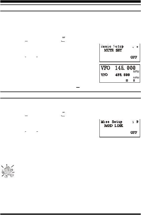
1.Press the  key, then press the
  key to enter the Set mode.
2.Rotate the DIAL to select the Menu Item labeled (Basic 
Operation #8: MUTE SET).
3.Press the  or
or  key to select “ON” (to enable Audio Mute feature).
4.Press the PTT switch to save the new setting and exit to
normal operation. 5. To disable the Audio Mute feature, select “OFF” in step 3
above.
When the Audio Mute feature is activated, the “ 


 ” icon will appear on the display.
BAND LINKING
For split operation on Amateur bands, the BAND Link feature may be useful.
1.Set up dual receive operation, as just described.
2.Press the  key, then press the
  key to enter the Set mode.
3.Rotate the DIAL to select the Menu Item labeled (Misc 
Setup #9: BAND LINK).
4.Press the  or
or  key to set this Menu Item to ON.
5.Press the PTT key to save the new setting and exit to Linked/Dual receive operation.
As you rotate the DIAL, you will observe that both bands’ frequencies are changing together. When you are done with this operating mode, re-enter the Set mode, and set (Misc Setup #9: BAND LINK) to OFF.
The BAND Link feature requires that (1) “Main” band and “Sub” band be set to same band (Dual In-band receive), (2) Menu Item ( Misc Setup #10: VFO MODE ) must be set to “BAND.” In other words, the BAND Link feature
cannot activated if “Main” band and “Sub” band are not set to the same band, or if Menu Item ( Misc Setup #10: VFO MODE ) is set to “ALL.”
VX-7R OPERATING MANUAL |
17 |
OPERATION
TRANSMISSION
Once you have set up an appropriate frequency inside one of the three (or four) Amateur bands on which the VX-7R can transmit (50 MHz, 144 MHz, or 430 MHz, plus 222 MHz on the USA version), you’re ready to transmit. These are the most basic steps; more advanced aspects of transmitter operation will be discussed later.
1.To transmit, press the PTT switch, and speak into the front panel microphone (located in the upper right-hand corner of the speaker grille) in a normal voice level. The “STROBE” will glow red during transmission.
2.To return to the receive mode, release the PTT switch.
3.During transmission, the relative power level will be indicated on the LCD. Full power (5 Watts) is indicated by eight arrows below the frequency display. The three “Low Power” levels (L1, L2, and L3) are indicated by two, four, or six arrows, respectively. Additionally, the “L1,” “L2,” or “L3” icon will appear at the bottom of the display, corresponding with the “Low Power” Level setting.
If you’re just talking to friends in the immediate area, you’ll get much longer battery life by switching to Low Power operation. To do this, press the  key, then press the
  key so that the “L” icon appears at the bottom of the
display. And don’t forget: always have an antenna connected when you transmit.
Transmission is not possible on any operating bands other than the 50 MHz, 144 MHz, 222 MHz, and 430 MHz bands.
Changing the Transmitter Power Level
You can select between a total of four transmitter power levels on your VX-7R. The exact power output will vary somewhat, depending on the voltage supplied to the transceiver.
With the standard FNB-80LI Battery |
|
|
ICONS |
|
||
Pack and external DC source, the power |
|
NONE |
L3 |
L2 |
L1 |
|
output levels available are: |
50/144/430 MHz |
5.0 W |
2.5 W |
1.0 W |
0.05 W |
|
222 MHz FM |
– |
– |
0.3 W |
0.05 W |
||
|
||||||
To change the power level: |
50 MHz AM |
|
1.0 W (Fixed) |
|
||
1.The default setting for the power output is “High;” in this configuration, the LCD shows no indication of the power output level. Pressing the  key, followed by the
  key, causes the power level “L1,” “L2,” or “L3” to appear.
2.Press the  key, followed by the
  key (repeatedly, if necessary) to make the “Low Power” icon disappear and restore High Power operation.
1) The VX-7R is smart! You can set up Low power on one band (like UHF), while leaving VHF on High power, and the radio will remember the different settings on each band. And when you store memories, you can store High
and Low power settings separately in each memory, so you don’t waste battery power when using very close-in repeaters!
18 |
VX-7R OPERATING MANUAL |
OPERATION
TRANSMISSION
2) When you are operating on one of the Low power settings, you can press the  key, then press the PTT switch, to cause the VX-7R to transmit (temporarily) on High power. After one transmission, the power level will revert to the previously-selected Low power setting.
VOX OPERATION
The VOX system provides automatic transmit/receive switching based on voice input to the microphone. With the VOX system enabled, you do not need to press the PTT switch in order to transmit, and it is not necessary to use a VOX headset in order to utilize VOX operation.
1.Press the  key, then press the
  key to enter the Set mode.
2.Rotate the DIAL to select the Menu Item labeled (Misc 
Setup #7: VOX SENS).
3.Press the  or
or  key to select the desired VOX Gain level (“HIGH” or “LOW”).
4.When you have made your choice, press the PTT key to save the new setting and return to normal operation.
5.Without pressing the PTT switch, speak into the microphone in a normal voice level. When you start speaking, the transmitter should be activated automatically. When you finish speaking, the transceiver should return to the receive mode (after a short delay).
6.To cancel VOX and return to PTT operation, just repeat 
the above procedures, selecting “OFF” in step 3 above.
When the VOX system is activated, the “

 ” icon will appear on the display.
The VX-7R provides for adjustment of the “Hang-Time” of the VOX system (the transmitreceive delay after the cessation of speech) via the Menu. The default delay is 1/2 second. To set a different delay time:
1.Press the  key, then press the
  key to enter the Set mode.
2.Rotate the DIAL to select the Menu Item labeled (Misc 
Setup #8: VOX DELAY).
3.Press the  or
or  key to select the delay time among “0.5sec,” “1sec,” and “2sec.”
4.When you have made your choice, press the PTT key to save the new setting and return to normal operation.
VX-7R OPERATING MANUAL |
19 |
OPERATION
AM BROADCAST RECEPTION
The VX-7R includes provision for reception of AM broadcasts, either on the standard medium-wave (MW) broadcast band, or on the shortwave bands up to 16 MHz.
1.Set the VX-7R to the VFO mode on the “Main” band.
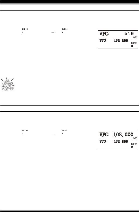
2.Press the  key (or press
  à
à  ) repetitively until
you see a frequency in the frequency range desired. The MW coverage is 0.5 MHz to 1.8 MHz, while the short-
wave broadcast coverage is 1.8 MHz to 16 MHz. In either
case, the operating mode (displayed on the right edge of the LCD) should be shown as being “AM.”
3.Rotate the DIAL to tune across the broadcast band.
4.You may also use the keypad to enter frequencies directly. This method will be quicker for changing from the 49-meter broadcast band to the 31-meter band, for example.
1) If the operating mode is not correct, you may need to adjust the setting of the Menu Item labeled ( Basic Setup #4: RX MODE ). See page 26 for details. 2) The VX-7R includes a special memory bank into which the factory has
stored 89 frequencies representing popular Short-wave Broadcast stations. See page 55 for details.
AM AIRCRAFT RECEPTION
Reception of AM signals in the aeronautical band (108-137 MHz) is similar to that described in the previous section.
1.Be sure that the VX-7R is set to the VFO mode on the “Main” band.
2.Press the  key (or press
  à
à  ) repetitively until
you see a frequency in the aeronautical band. 3. Rotate the DIAL to tune across the aeronautical band.
4. You may also use the keypad to enter frequencies directly.
Remember that frequencies quoted by aircraft operators may be abbreviated, and that the “5” at the end of a frequency may be dropped. Since aeronautical channels are assigned in 25-kHz steps, therefore, a frequency announced as “thirty-two, forty-two” corresponds to an operating frequency of 132.425 MHz.
20 |
VX-7R OPERATING MANUAL |
OPERATION
FM BROADCAST/TV AUDIO RECEPTION
The VX-7R also includes provision for reception in the FM broadcast band, utilizing a wide-bandwidth filter which provides excellent fidelity.
To Activate FM Broadcast Reception
1.Be sure that the VX-7R is set to the VFO mode on the “Main” band.
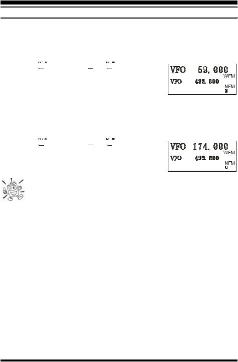
2.Press the  key (or press
  à
à  ) repetitively until
a frequency in the FM broadcast band appears on the display. The total frequency range included in the “FM” band is 59-108 MHz.
3.Rotate the DIAL to select the desired station. The default synthesizer steps for the W- FM mode are 100 kHz/step.
To Activate VHF or UHF TV Audio Reception
1.Be sure that the VX-7R is set to the VFO mode on the “Main” band.
2.Press the  key (or press
  à
à  ) repetitively until
a frequency in the VHF or UHF TV bands appears on the LCD.
3. Rotate the DIAL to select the desired station.
Remember that the Wide-FM Squelch setting may be made independently from the Narrow-FM setting, using the Menu Item labeled (Basic Setup #2: SQL WFM). See page 84.
VX-7R OPERATING MANUAL |
21 |
OPERATION
WEATHER BROADCAST RECEPTION
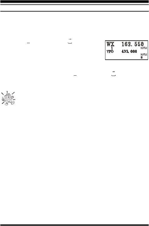
The VX-7R includes a unique feature which allows reception of weather broadcasts in the 160-MHz frequency range. Ten standard Weather Broadcast channels are pre-loaded into a special memory bank.
To listen to a Weather Broadcast Channel or VHF Marine Channel:
1. Press the  key, then press the
  key to recall the Weather Broadcast channels.
2. Turn the DIAL knob to select the desired Weather Broadcast channel.
3.If you wish to check the other channels for activity by scanning, just press the PTT switch.
4.To exit to normal operation, again the  key, then press the
  key. Operation will return to the VFO or Memory channel you were operating on before you began Weather Broadcast operation.
In the event of extreme weather disturbances, such as storms and hurricanes, the NOAA (National Oceanic and Atmospheric Administration) sends a weather alert accompanied by a 1050 Hz tone and subsequent weather report
on one of the NOAA weather channels. You may disable the Weather Alert tone via Menu Item (Misc Setup #20 WX ALERT), if desired.
22 |
VX-7R OPERATING MANUAL |
OPERATION
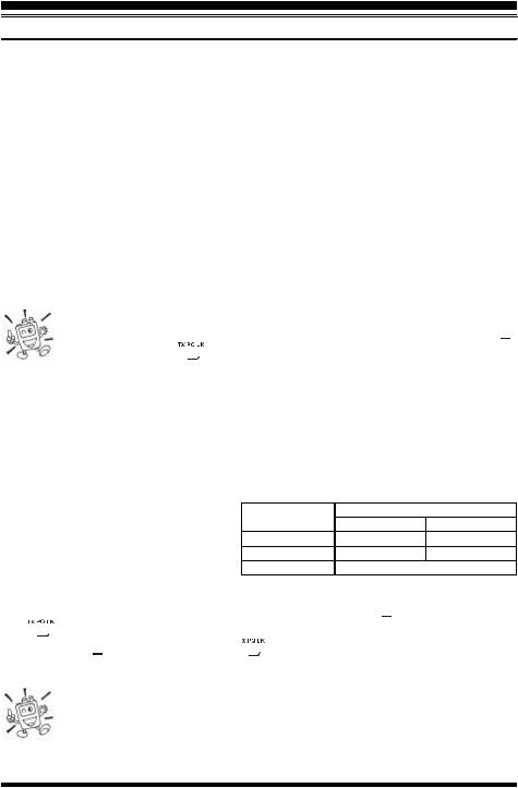
KEYBOARD LOCKING
In order to prevent accidental frequency change or inadvertent transmission, various aspects of the VX-7R’s keys and switches may be locked out. The possible lockout combinations are:
KEY: Just the front panel keys are locked out
DIAL: Just the top panel DIAL is locked out
KEY+DIAL: Both the DIAL and Keys are locked out
PTT: The PTT switch is locked (TX not possible)
KEY+PTT: Both the keys and PTT switch are locked out
DIAL + PTT:Both the DIAL and PTT switch are locked out
ALL: All of the above are locked out
To lock out some or all of the keys:
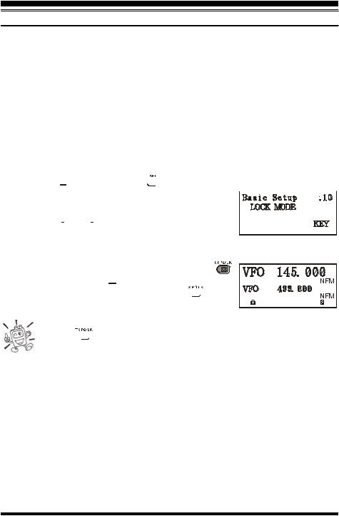
1.Press the  key, then press the
  key to enter the Set mode.
2.Rotate the DIAL to select the Menu Item labeled (Basic 
Setup #10: LOCK MODE).
3.Press the  or
or  key to choose between one of the locking schemes as outlined above.
4.When you have made your selection, press the PTT switch to save the new setting and
resume normal operation.
5. To activate the locking feature, press and hold in the
key for 2 seconds. The “ 


 ” icon will appear on the LCD. To cancel locking, again press and hold the
  key for 2 seconds.
Even when “ALL” keys have been locked out, one key actually is not locked out: the  key remains available so you can unlock your keypad when you want to!
VX-7R OPERATING MANUAL |
23 |
OPERATION
KEYPAD/LCD ILLUMINATION
Your VX-7R includes a reddish illumination lamp which aids in nighttime operation. The red illumination yields clear viewing of the display in a dark environment, with minimal degradation of your night vision. Three options for activating the lamp are provided:
KEY Mode: |
Illuminates the Keypad/LCD for 5 seconds when any key pressed. |
CONTINUE Mode: Illuminates the Keypad/LCD continuously. |
|
OFF Mode: |
Disables the Keypad/LCD lamp. |
Here is the procedure for setting up the Lamp mode:
1.Press the  key, then press the
  key to enter the Set mode.
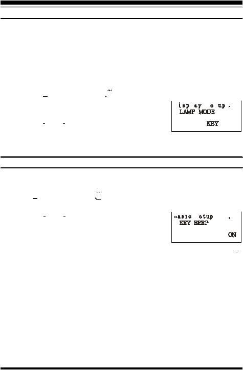
2.Rotate the DIAL to select the Menu Item labeled (Display 
Setup #5: LAMP MODE).
3. Press the  or
or  key to select one of the three modes described above.
4.When you have made your choice, press the PTT key to save the new setting and return to normal operation.
DISABLING THE KEYPAD BEEPER
If the keypad’s Beeper creates an inconvenience (particularly when operating in a quiet room), it may easily be disabled.
1.Press  key, then press the
  key to enter the Set mode.
2.Rotate the DIAL to select the Menu Item labeled (Basic Setup #9: KEY BEEP).
3.Press the  or
or  key to change the setting from ON
to OFF.
4.When you have made your selection, press the PTT key to save the new setting and exit to normal operation.
5.If you wish to re-enable the Beeper, just repeat the above procedure, pressing the  or
or  key to select ON in step “3” above.
24 |
VX-7R OPERATING MANUAL |
ADVANCED OPERATION
Now that you’re mastered the basics of VX-7R operation, let’s learn more about some of the really neat features.
SETTING THE FREQUENCY DISPLAY IMAGE SIZE
VFO Mode
When operating in the VFO mode during the “Mono” band operation, pressing the  key, then pressing the
  or
or  key, causes the LCD to “toggle” between display of doublesize characters and large characters. However, this feature does not work during Dual Receive operation, as two frequencies are displayed in that instance.
Memory Mode
When operating in the Memory mode (see page 45), pressing the  key, followed by the
  or
or  key, causes the LCD to “toggle” between display of the current memory’s frequency (in double-size characters) and the current memory’s frequency (in large characters) with its alpha-numeric Tag (small characters). This feature likewise does not activate during Dual Receive operation.
CHANGING THE CHANNEL STEPS
The VX-7R’s synthesizer provides the option of utilizing channel steps of 5/9/10/12.5/15/ 20/25/50/100 kHz per step, any number of which may be important to your operating requirements. The VX-7R is set up at the factory with different default steps on each operating band which probably are satisfactory for most operation. However, if you need to change the channel step increments, the procedure to do so is very easy.
1.Press the  key, then press the
  key to enter the Set mode.
2.Rotate the DIAL to select the Menu Item labeled (Basic Setup #3: VFO STEP).
3.Press the  or
or  key to select the new channel step
size.
4.Press the PTT key to save the new setting and exit to normal operation.
9 kHz step is available on the BC band only.
VX-7R OPERATING MANUAL |
25 |
ADVANCED OPERATION
CHANGING THE OPERATING MODE
The VX-7R provides for automatic mode changing when the radio is tuned to different operating frequencies. However, should an unusual operating situation arise in which you need to change between the available operating modes (FM-Narrow, FM-Wide, and AM), here is the procedure for doing so:
1.Press the  key, then press the
  key to enter the Set mode.
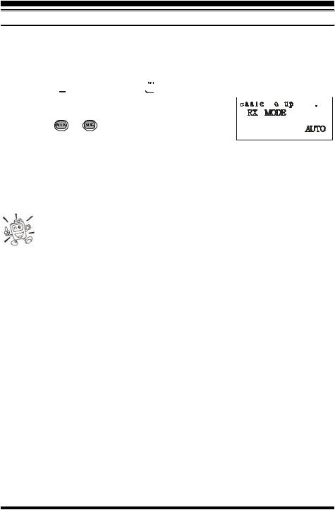
2.Rotate the DIAL to select the Menu Item labeled (Basic 
|
Setup #4: RX MODE). |
|||
3. |
Press the |
or |
key to select the new channel step |
|
|
size. The available selections are: |
|||
|
AUTO: |
Automatic mode setting per default values for the selected frequency range.. |
||
|
N-FM: |
Narrow-bandwidth FM (used for voice communication) |
||
|
W-FM: |
Wide-bandwidth FM (used for high-fidelity broadcasting) |
||
|
AM: |
Amplitude Modulation |
||
4. |
Press the PTT key to save the new setting and exit to normal operation. |
|||
Unless you have a compelling reason to do so, leave the Automatic Mode Selection feature on so as to save time and trouble when changing bands. If you make a mode change for a particular channel or station, you can always
store that one channel into memory, as the mode setting will be memorized along with the frequency information.
26 |
VX-7R OPERATING MANUAL |
ADVANCED OPERATION
REPEATER OPERATION
Repeater stations, usually located on mountaintops or other high locations, provide a dramatic extension of the communication range for low-powered hand-held or mobile transceivers. The VX-7R includes a number of features which make repeater operation simple and enjoyable.
Repeater Shifts
Your VX-7R has been configured, at the factory, for the repeater shifts customary in your country. For the 50 MHz band, this usually will be 1 MHz, while the 144 MHz shift will be 600 kHz; on 70 cm, the shift may be 1.6 MHz, 7.6 MHz, or 5 MHz (USA version).
Depending on the part of the band in which you are operating, the repeater shift may be either downward (–) or upward (+), and one of these icons will appear at the bottom of the LCD when repeater shifts have been enabled.
Automatic Repeater Shift (ARS)
The VX-7R provides a convenient Automatic Repeater Shift feature, which causes the appropriate repeater shift to be automatically applied whenever you tune into the designated repeater sub-bands in your country. These sub-bands are shown below.
If the ARS feature does not appear to be working, you may have accidentally disabled it.
To re-enable ARS:
1.Press the  key, then press the
  key to enter the Set mode.
2.Rotate the DIAL to select the Menu Item labeled (Basic Setup #5: ARS).
3.Press the  or
or  key to select “ON” (to enable Automatic Repeater Shift).
4.Press the PTT key to save the new setting and exit to normal operation.
ARS-Repeater Subbands
2-m Version A
|
|
|
|
|
|
|
|
|
|
|
|
|
|
|
|
|
|
|
|
|
|
|
|
|
|
|
|
|
|
|
|
145.1 |
145.5 |
146.0 |
|
146.4 |
|
|
|
147.0 |
|
|
147.6 |
|
148.0 |
||||||||||||||||||
|
|
|
|
|
|
|
|
|
|
|
|
|
|
|
|
|
|
|
|
|
|
|
|
|
|
|
|
|
|
|
|
|
|
|
|
|
|
|
|
|
|
|
|
|
|
|
|
|
|
|
|
|
|
|
|
|
|
||||||
|
|
|
|
|
|
|
|
|
|
|
|
|
|
|
146.6 |
|
|
|
|
147.4 |
|
|
|
|
|
||||||
|
|
145.6 145.8 |
|
|
|
|
|
|
|
|
|||||||||||||||||||||
|
|
|
|
|
|
|
|
|
|
|
|
|
|
|
|
|
|
|
|
||||||||||||
|
|
|
|
|
|
|
|
|
|
|
|
|
European Version |
|
|
|
|
|
|
|
|||||||||||
|
|
|
|
|
|
|
|
|
|
|
|
|
|
|
|
|
70-cm |
|
|
|
|
|
|
|
|
|
|
||||
|
|
|
|
|
|
|
|
|
|
|
|
|
|
|
|
|
|
|
|
|
|
|
|
|
|
|
|
|
|
|
|
Version A |
440.0 |
|
|
445.0 |
|
|
|
|
450.0 |
||||||||||||||||||||||
|
|
|
|
|
|
|
|
|
|
|
|
|
|
|
|
|
|||||||||||||||
|
|
|
|
|
|
|
|
|
|
|
|
|
|
|
|
|
|
|
|
|
|
|
|||||||||
|
|
|
|
|
|
|
|
|
438.20 |
|
|
|
439.45 |
Euro Version 1 |
|
|
|||||||||||||||
|
|
|
|
|
|
|
|
|
|
|
|
|
|||||||||||||||||||
433.00 |
|
|
|
|
|
|
433.40 Euro Version 2 |
|
|
|
|
|
|
|
|||||||||||||||||
VX-7R OPERATING MANUAL |
27 |

ADVANCED OPERATION
REPEATER OPERATION
Manual Repeater Shift Activation
If the ARS feature has been disabled, or if you need to set a repeater shift direction other than that established by the ARS, you may set the direction of the repeater shift manually.
To do this:
1.Press the  key, then press the
 key to enter the Set mode.
2.Rotate the DIAL to select the Menu Item labeled (Basic 
Setup #7: RPT SHIFT). 3. Press the  or
or  key to select the desired shift among
“–RPT,” “+RPT,” and “SIMP.”
4. Press the PTT key to save the new setting and exit to normal operation.
Changing the Default Repeater Shifts
If you travel to a different region, you may need to change the default repeater shift so as to ensure compatibility with local operating requirements.
To do this, follow the procedure below:
1.Press the  key, then press the
  key to enter the Set mode.
2.Rotate the DIAL to select the Menu Item labeled (Basic 
Setup #6: SHIFT). 3. Press the  or
or  key to select the new repeater shift
magnitude.  4. Press the PTT key to save the new setting and exit to normal operation.
If you just have one “odd” split that you need to program, don’t change the “default” repeated shifts using this Menu Item! Enter the transmit and receive frequencies separately, as shown on page 46.
28 |
VX-7R OPERATING MANUAL |
 Loading...