


VX-600V
Operating Manual
VERTEX STANDARD CO., LTD.
4-8-8 Nakameguro, Meguro-Ku, Tokyo 153-8644, Japan
VERTEX STANDARD
US Headquarters
17210 Edwards Rd., Cerritos, CA 90703, U.S.A.
International Division
8350 N.W. 52nd Terrace, Suite 201, Miami, FL 33166, U.S.A.
YAESU EUROPE B.V.
P.O. Box 75525, 1118 ZN Schiphol, The Netherlands
YAESU UK LTD.
Unit 12, Sun Valley Business Park, Winnall Close
Winchester, Hampshire, SO23 0LB, U.K.
YAESU GERMANY GmbH
Am Kronberger Hang 2, D-65824 Schwalbach, Germany
VERTEX STANDARD HK LTD.
Unit 5, 20/F., Seaview Centre, 139-141 Hoi Bun Road, Kwun Tong, Kowloon, Hong Kong

|
Contents |
Warning! FCC RF Exposure Requirements |
................................................................................................ 1 |
Controls & Connectors ................................................................................................................................... |
2 |
Before You Begin ............................................................................................................................................ |
3 |
Battery Pack Installation and Removal ........................................................................................................ |
3 |
Low Battery Indication ................................................................................................................................ |
3 |
Operation ......................................................................................................................................................... |
4 |
Preliminary Steps ......................................................................................................................................... |
4 |
Operation Quick Start .................................................................................................................................. |
4 |
Advanced Operation ....................................................................................................................................... |
7 |
Soft Key and TOGGLE Switch Functions .................................................................................................. |
7 |
ARTS (Auto Range Transpond System) .................................................................................................... |
13 |
DTMF Paging System ............................................................................................................................... |
13 |
Understanding Radio Waves ....................................................................................................................... |
14 |
Accessories & Options .................................................................................................................................. |
15 |
Congratulations!
You now have at your fingertips a valuable communications tool-a VERTEX STANDARD two-way radio!
Rugged, reliable and easy to use, your VERTEX STANDARD radio will keep you in constant touch with your colleagues for years to come, with negligible maintenance down-time.
Please take a few minutes to read this manual carefully. The information presented here will allow you to derive maximum performance from your radio, in case questions arise later on.
We're glad you joined the VERTEX STANDARD team. Call on us anytime, because communications is our business. Let us help you get your message across.
Notice!: There are no owner-serviceable parts inside the transceiver. All service jobs must be referred to an authorized VERTEX STANDARD Service Representative. Consult your Authorized VERTEX STANDARD Dealer for installation of optional accessories.

WARNING! FCC RF EXPOSURE REQUIREMENTS
FCC RF Exposure Compliance Requirements for Occupational Use Only:
This Radio has been tested and complies with the Federal Communications Commission (FCC) RF exposure limits for Occupational Use/Controlled exposure environment. In addition, it complies with the following Standards and Guidelines:
rFCC 96-326, Guidelines for Evaluating the Environmental Effects of Radio-Frequency Radiation.
rFCC OET Bulletin 65 Edition 97-01 (1997) Supplement C, Evaluating Compliance with FCC Guidelines for Human Exposure to Radio Frequency Electromagnetic Fields.
rANSI/IEEE C95.1-1992, IEEE Standard for Safety Levels with Respect to Human Exposure to Radio Frequency Electromagnetic Fields, 3 kHz to 300 GHz.
rANSI/IEEE C95.3-1992, IEEE Recommended Practice for the Measurement of Potentially Hazardous Electromagnetic Fields - RF and Microwave.
¦This radio is NOT approved for use by the general population in an uncontrolled exposure environment. This radio is restricted to occupational use, work related operations only where the radio operator must have the knowledge to control his or her RF exposure conditions.
¦When transmitting, hold the radio in a vertical position with its microphone 2 inches (5 cm) away from your mouth and keep the antenna at least 2 inches (5 cm) away from your head and body.
¦The radio must be used with a maximum operating duty cycle not exceeding 50%, in typical Push-to- Talk configurations.
DO NOT transmit for more than 50% of total radio use time (50% duty cycle). Transmitting more than 50% of the time can cause FCC RF exposure compliance requirements to be exceeded.
The radio is transmitting when the red LED on the top of the radio is illuminated. You can cause the radio to transmit by pressing the P-T-T button.
¦SAR compliance for body-worn use was only demonstrated for the specific belt-clip Part Number (#BA0102700112KA). Other body-worn accessories or configurations may NOT comply with the FCC RF exposure requirements and should be avoided.
¦Always use Vertex Standard authorized accessories.
 1
1
VX-600V OPERATING MANUAL

CONTROLS & CONNECTORS
CH (Channel) Selector
Antenna Jack |
TOP SEL (Selector) Key |
Speaker
SIDE SEL
(Selector) Key
PTT (Push To Talk) 


Switch
MONITOR Button
LAMP Button
LED Indicator
Steady Green: Signaling off
Blinking Green: Busy Channel (or Squelch off) Steady Red: Transmission in Progress Blinking Red: Battery voltage is low
Blinking Yellow: Receiving a Selective Call
VOL/PWR (Volume/Power) Knob
TOGGLE Switch
MIC/SP Jack
(External Microphone/
Speaker)


 Sub Microphone
(Noise Canceling Microphone)
16-Button DTMF Keypad |
Battery Pack Latch |
Main Microphone |
(16-key version only)
2 
VX-600V OPERATING MANUAL
BEFORE YOU BEGIN
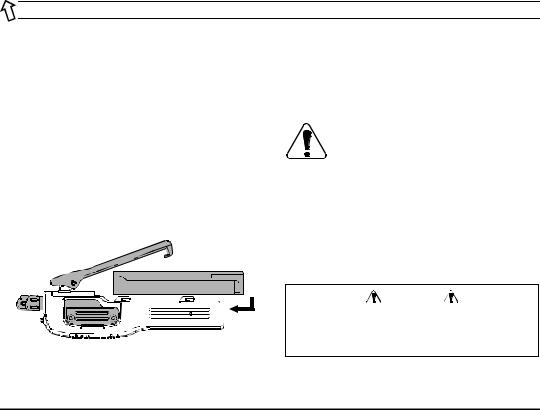
Battery Pack Installation and Removal
rTo install the battery, hold the transceiver with your left hand, so your palm is over the speaker and your thumb is on the top of the belt clip. Carefully mate the battery’s four insertion slots with their corresponding alignment tabs on the transceiver case, while tilting the Belt Clip outward. Proper alignment occurs with the battery pack offset about 1/2 inch from the top edge of the battery compartment.
rGuide the pack on to the tabs with a slight inward pressure, then slide the battery pack upward, until it locks in place with a “Click.”
Tilt the Belt Clip
rTo remove the battery, turn the radio off and remove any protective case. Slide the Battery Pack Latch on the bottom of the radio toward the front panel while sliding the battery down about 1/2 inch. Then lift the battery out from the radio while unfolding the Belt Clip.
Do not attempt to open any of the rechargeable Lithium-Ion packs, as they could explode if accidentally short-circuited.
Low Battery Indication
As the battery discharges during use, the voltage gradually becomes lower. When the battery voltage reaches 6.0 volts, it is time to substitute a freshly charged battery and recharge the depleted pack. The LED indicator on the top of the radio will blink red when the battery voltage is low (6 Volts or lower).
|
Caution |
|
Danger of explosion if battery is replaced with |
|
an incorrect battery. Replace only with the same |
Insert the Battery Pack |
or equivalent type. |
 3
3
VX-600V OPERATING MANUAL
OPERATION
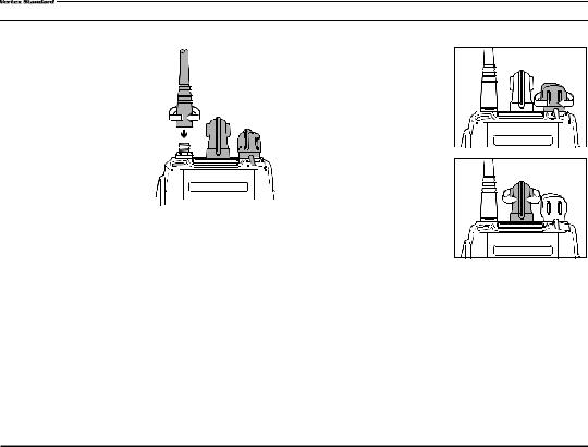
Preliminary Steps
r Install a charged battery pack onto the transceiver, as described previously.
r Screw the supplied antenna onto the Antenna jack. Never attempt to operate this transceiver without an antenna connected.
rIf you have a Speaker/ 


 Microphone, we recommend that it not be connected until you are familiar with the basic operation of the VX-600.
Quick Start
r Turn the top panel’s
V O L / P W R k n o b clockwise to turn on the radio on.
r Turn the top panel’s CH selector knob to
choose the desired operating channel. If you want to select an operating channel from a
d i f f e r e n t M e m o r y
Channel Group, press the Soft key (assigned to the Memory Group Up or Down function) to select the Memory Channel Group you want before selecting the operating channel.
Note: Some models are programmed so that the operating channels are selected by the Soft key and the memory channel group is selected by the CH selector knob. For further details, contact your
VERTEX STANDARD dealer.
4 
VX-600V OPERATING MANUAL
 Loading...