


VX-450 SERIES
OPERATING MANUAL
VX-451 |
VX-454 |
VX-459 |
PROGRAMMABLE FUNCTIONS/FEATURES
IP57 Submersible (1 m/30 min.)
Programmable Function Keys
2-tone Encode/Decode
5-tone Encode/Decode
MDC-1200® Encode/Decode
Scan
Group Scan
Dual Watch
FM-Scan (Follow-Me Scan)
TA Scan
Encryption
Clear Voice
VOX
REC & PLAY (Requires DVS-8 or DVS-9)
AF Min Volume
Talk Around
Man Down (Requires DVS-9)
Emergency
Lone Worker
Direct Channel Entry1
Code Up/Down1
Code Set1
Speed Dial1
DTMF Code Set2
ID Check1
TX Save Disable
ARTS (Auto Range Transpond System)
1: VX-454 & VX-459 ONLY 2: VX-459 ONLY

CONTENTS
Introduction ................................................................... |
1 |
Warning! FCC RF Exposure Requirements ............... |
2 |
Controls & Connectors (VX-459) ................................ |
4 |
Controls & Connectors (VX-454) ................................ |
5 |
Controls & Connectors (VX-451) ................................ |
6 |
LCD Icons & Indicators (VX-454 & VX-459) ............ |
7 |
Before You Begin ........................................................... |
8 |
Battery Pack Installation and Removal ...................... |
8 |
Low Battery Indication .............................................. |
8 |
Battery Charging ........................................................ |
8 |
Belt Clip Installation and Removal .......................... |
10 |
Operation ..................................................................... |
12 |
Preliminary Steps ..................................................... |
12 |
Operation Quick Start .............................................. |
12 |
Advanced Operation ................................................... |
16 |
Programmable Key Functions ................................. |
16 |
Description of Operating Functions ........................ |
18 |
Man Down Function .................................................... |
29 |
ARTS (Auto Range Transpond System) ................... |
29 |
LOCK ........................................................................... |
29 |
User Set Mode .............................................................. |
30 |
Optional Accessories.................................................... |
31 |
CONGRATULATIONS!
You now have at your fingertips a valuable communications tool-a Vertex Standard two-way radio! Rugged, reliable and easy to use, your Vertex Standard radio will keep you in constant touch with your colleagues for years to come, with negligible maintenance down-time. Please take a few minutes to read this manual carefully. The information presented here will allow you to derive maximum performance from your radio, in case questions arise later on.
We’re glad you joined the Vertex Standard team. Call on us anytime, because communications is our business. Let us help you get your message across.
Notice!: There are no owner-serviceable parts inside the radio. All service jobs must be referred to an authorized Vertex Standard Service Representative. Consult your Authorized Vertex Standard Dealer for installation of optional accessories.

INTRODUCTION
The VX-450 Series are full-featured hand-held FM transceivers designed for business communications in the VHF or UHF Land Mobile bands. These transceivers are designed for reliable business communications in a wide variety of applications with a wide range of operating capability provided by their leading-edge design.
The VX-451 allows to 32-channel capacity and 2 groups. The VX-454/-459 allows to 512-channel capacity and 32 groups which can each be programmed with an 8-character Alpha-Numeric Tag.
Important channel frequency data is stored in EEPROM and flash memory on the CPU, and is easily programmable by Vertex Standard dealers using a personal computer and the Vertex Standard Programming Cable and CE115 Software.
The pages which follow will detail the many advanced features provided in the VX-450 Series transceiver. After reading this manual, you may wish to consult with your Network Administrator regarding precise details of the configuration of this equipment for use in your application.
IMPORTANT NOTICE FOR NORTH AMERICAN USERS REGARDING 406 MHZ GUARD BAND
The U.S. Coast Guard and National Oceanographic and Atmospheric Administration have requested the cooperation of the U.S. Federal Communications Commission in preserving the integrity of the protected frequency range 406.0 to 406.1 MHz, which is reserved for use by distress beacons. Do not attempt to program this apparatus, under any circumstances, for operation in the frequency range 406.0 - 406.1 MHz if the apparatus is to be used in or near North America.
Warning - Frequency band 406 - 406.1 MHz is reserved for use ONLY as a distress beacon by the US Coast Guard and NOAA. Under no circumstance should this frequency band be part of the preprogrammed operating frequencies of this radio.
1
VX-450 SERIES OPERATING MANUAL
WARNING! FCC RF EXPOSURE REQUIREMENTS
This Radio has been tested and complies with the Federal Communications Commission (FCC) RF exposure limits for Occupational Use/Controlled exposure environment. In addition, it complies with the following Standards and Guidelines:
FCC 96-326, Guidelines for Evaluating the Environmental Effects of Radio-Frequency Radiation.
FCC OET Bulletin 65 Edition 97-01 (2001) Supplement C, Evaluating Compliance with FCC Guidelines for Human Exposure to Radio Frequency Electromagnetic Fields.
ANSI/IEEE C95.1-1992, IEEE Standard for Safety Levels with Respect to Human Exposure to Radio Frequency Electromagnetic Fields, 3 kHz to 300 GHz.
ANSI/IEEE C95.3-1992, IEEE Recommended Practice for the Measurement of Potentially Hazardous Electromagnetic Fields - RF and Microwave.

 WARNING:
This radio generates RF electromagnetic energy during transmit mode. This radio is designed for and classified as Occupational Use Only, meaning it must be used only during the course of employment by individuals aware of the hazards, and the ways to minimize such hazards. This radio is not intended for use by the General Population in an uncontrolled environment.


 CAUTION:
To ensure that your expose to RF electromagnetic energy is within the FCC allowable limits for occupational use, always adhere to the following guidelines:
This radio is NOT approved for use by the general population in an uncontrolled exposure environment. This radio is restricted to occupational use, work related operations only where the radio operator must have the knowledge to control his or her RF exposure conditions.
When transmitting, hold the radio in a vertical position with its microphone 2 inches (5 cm) away from your mouth and keep the antenna at least 2 inches (5 cm) away from your head and body.
2
VX-450 SERIES OPERATING MANUAL

WARNING! FCC RF EXPOSURE REQUIREMENTS
The radio must be used with a maximum operating duty cycle not exceeding 50%, in typical Push-to- Talk configurations.
DO NOT transmit for more than 50% of total radio use time (50% duty cycle). Transmitting more than 50% of the time can cause FCC RF exposure compliance requirements to be exceeded.
The radio is transmitting when the red LED on the top of the radio is illuminated. You can cause the radio to transmit by pressing the P-T-T button.
SAR compliance for body-worn use was only demonstrated for the specific belt-clip (CLIP-20). Other body-worn accessories or configurations may NOT comply with the FCC RF exposure requirements and should be avoided.
DO NOT transmit when the radio is used in Body Worn configuration with the following accessory: belt-clip.
It must be used ONLY for (1) there is 4 cm distance from the body during transmitting, (2) monitoring purposes, using the speaker only and (3) for carrying purposes.
Always use Vertex Standard authorized accessories.
The information listed above provides the user with the information needed to make him or her aware of RF exposure, and what to do to assure that this radio operates with the FCC RF exposure limits of this radio.
Electromagnetic Interference/Compatibility
During transmissions, this radio generates RF energy that can possibly cause interference with other devices or systems. To avoid such interference, turn off the radio in areas where signs are posted to do so. Do not operate the transmitter in areas that are sensitive to electromagnetic radiation such as hospitals, health care facilities, aircraft, and blasting sites.
3
VX-450 SERIES OPERATING MANUAL

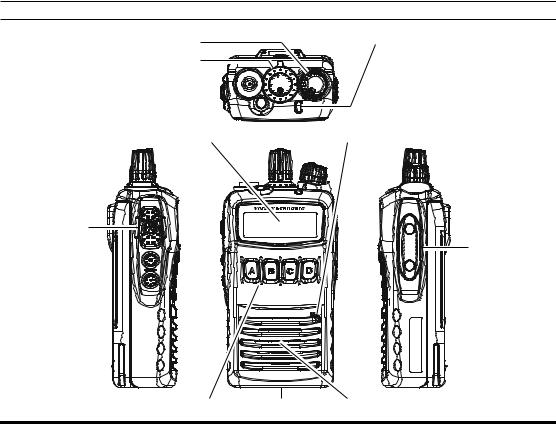
CONTROLS & CONNECTORS (VX-459)
VOL/PWR Knob
CH (Channel) Selector
Antenna Jack 


TOP SEL Key 
LCD (Liquid Crystal Display)
PTT Switch
SIDE-1 Button 
SIDE-2 Button 
LED Indicator (Programmable)
Default settings are:
Steady Red:
Transmitting in progress
Blinking Green:
Busy Channel
Steady Green:
Tone Squelch in defeated condition
Microphone
Jack MIC/SP
(External MIC/SP)
16-Button DTMF Keypad |
Battery Pack Latch |
Speaker |
4
VX-450 SERIES OPERATING MANUAL
CONTROLS & CONNECTORS (VX-454)
VOL/PWR Knob
CH (Channel) Selector
Antenna Jack 


TOP SEL Key 
LCD (Liquid Crystal Display)
PTT Switch
SIDE-1 Button 
SIDE-2 Button 
LED Indicator (Programmable)
Default settings are:
Steady Red:
Transmitting in progress
Blinking Green:
Busy Channel
Steady Green:
Tone Squelch in defeated condition
Microphone
Jack MIC/SP
(External MIC/SP)
4-Button Programmable Key |
Battery Pack Latch |
Speaker |
5
VX-450 SERIES OPERATING MANUAL
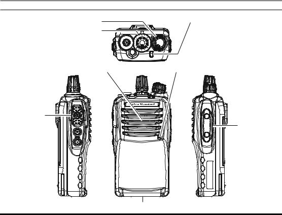
CONTROLS & CONNECTORS (VX-451)
VOL/PWR Knob
CH (Channel) Selector
Antenna Jack 


TOP SEL Key 
Speaker
PTT Switch
SIDE-1 Button 
SIDE-2 Button 
Battery Pack Latch
LED Indicator (Programmable)
Default settings are:
Steady Red:
Transmitting in progress
Blinking Green:
Busy Channel
Steady Green:
Tone Squelch in defeated condition
Microphone
Jack MIC/SP
(External MIC/SP)
6
VX-450 SERIES OPERATING MANUAL
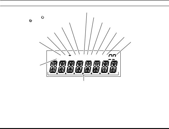
LCD ICONS & INDICATORS (VX-454 & VX-459)
|
“CALL” Indicator |
: “Scan” is enabled |
Receiver Monitor |
|
|
: “Priority Scan” is activated |
“Talk-Around” is enabled |
“DUAL WATCH” is activated |
“Voice Message” is received |
“Audio Compander” is activated |
Battery Indicator |
Low Transmit Power Mode On |
Priority 2 Channel |
Option SW (Key Function) |
Group Number |
is activated |
|
RSSI Indicator (four steps) 


 “Group Scan” is enabled
Encryption is activated
8 Character Alpha-numeric Display
7
VX-450 SERIES OPERATING MANUAL
BEFORE YOU BEGIN
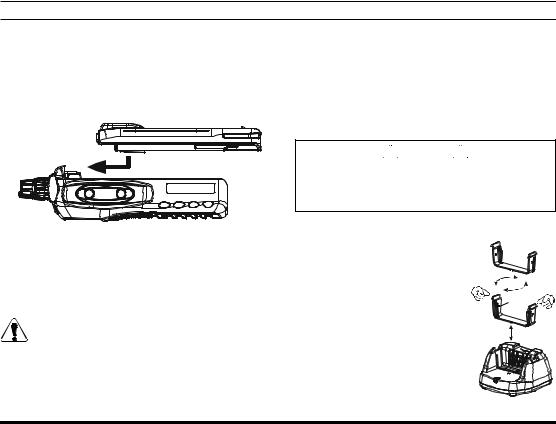
Battery Pack Installation and Removal
To install the battery pack, align the battery pack to the radio with an offset about 1/2 inch from the top edge of battery compartment, then slide the battery pack upward until it locks in place with a “Click.”
To remove the battery, turn the radio off and remove any protective cases. Slide the Battery Pack Latch on the bottom of the radio toward the front panel while sliding the battery down about 1/2 inch. Then lift the battery out from the radio.
Do not attempt to open any of the rechargeable Lithium-Ion packs, as they could ex-
plode if accidentally short-circuited.
Low Battery Indication
As the battery discharges during use, the voltage gradually becomes lower. When the battery voltage becomes to low, substitute a freshly charged battery and recharge the depleted pack. The LED indicator on the top of the radio will blink red when the battery voltage is low.


 Caution


Danger of explosion if battery is replaced with an incorrect battery. Replace only with the same or equivalent type.
Battery Charging
Referring to Figure 1, adjust the direction of the Battery Holder of the CD-49 Desktop Charger in accordance with the battery pack being charged; Push in both sides of the Battery Holder while pulling up on the Battery Holder to remove it from the charger base, select the correct direction of the Battery Holder for the battery being charged, then
Wide
Wide
FIGURE 1
8
VX-450 SERIES OPERATING MANUAL
BEFORE YOU BEGIN
replace the Battery Holder by pressing down on both sides of the Battery Holder, if necessary.
Referring to Figure 2, insert the DC plug from the optional PA-45 AC Adapter into the DC jack on the rear panel of the CD-49 Desktop Charger,
PA-45 |
and then plug the |
AC Adapter into the |
|
|
AC line outlet. |
|
|
|
Insert the battery pack into the |
Desktop |
|
Charger while aligning the slots of the battery pack with the guides in the nest of the CD-49; refer to the illustration at the right for details on proper positioning of the battery pack. If charging with the transceiver attached, turn the transceiver off. The antenna jack should be at the left side when viewing the charger from the front.
If the battery pack is inserted correctly, the LED indicator will glow red. A fully-discharged battery pack will charge completely in 1.5 - 3.0 hours (depending on the battery pack being charged).
When charging is completed, the LED indicator will change to green.
Disconnect the battery pack from the CD-49 Desktop Charger and unplug the PA-45 AC Adapter from the AC line outlet.


 WARNING


Perform the battery charging where the ambient tempera-ture range +5 °C to +35 °C. Charge out of this range could cause damage to the battery pack.
FIGURE 2
9
VX-450 SERIES OPERATING MANUAL
 Loading...