


OPERATING MANUAL
YAESU MUSEN CO., LTD.
4-8-8 Nakameguro, Meguro-Ku, Tokyo 153-8644, Japan
YAESU U.S.A.
17210 Edwards Rd., Cerritos, CA 90703, U.S.A.
YAESU EUROPE B.V.
P.O. Box 75525 1118 ZN, Schiphol, The Netherlands
YAESU UK LTD.
Unit 12, Sun Valley Business Park, Winnall Close
Winchester, Hampshire, SO23 0LB, U.K.
YAESU GERMANY GmbH
Am Kronberger Hang 2, D-65824 Schwalbach, Germany
YAESU HK LTD.
11th Floor Tsim Sha Tsui Centre, 66 Mody Rd.,
Tsim Sha Tsui East, Kowloon, Hong Kong

Contents
Introduction .......................................... |
1 |
Controls & Connectors ........................ |
2 |
Accessories & Options .......................... |
3 |
Basic Operation .................................... |
4 |
Battery Pack Installation and Removal ....... |
4 |
Antenna Installation .................................... |
5 |
Switching Power ON and OFF ................... |
6 |
Adjusting the Volume Level ....................... |
6 |
Squelch Setup ............................................. |
6 |
Transmitting ................................................ |
6 |
Frequency Navigation ................................. |
7 |
Changing the Transmitter Power Level ...... |
7 |
Changing the Channel Steps ....................... |
7 |
Repeater Operation ..................................... |
8 |
Automatic Repeater Shift (ARS) ............ |
8 |
Manual Repeater Shift Activation .......... |
8 |
Setting Repeater Tx Offset ...................... |
9 |
Checking the Repeater |
|
Uplink (Input) Frequency ... |
9 |
Keyboard Locking ...................................... |
9 |
Advanced Operation .......................... |
10 |
VFO Split Mode ....................................... |
10 |
Receive Battery Saver Setup ..................... |
10 |
Tx Battery Saver ....................................... |
11 |
Keypad/LCD Illumination ........................ |
11 |
Automatic Power-Off (APO) Feature ....... |
12 |
Checking the Battery Voltage ................... |
12 |
Disabling the BUSY/TX LED .................. |
12 |
Busy Channel Lock-Out (BCLO) ............. |
12 |
Disabling the Key pad Beeper .................. |
13 |
Programming the Key Functions .............. |
13 |
Transmitter Time-Out Timer (TOT) ......... |
13 |
Tone Calling (1750 Hz) ............................ |
14 |
ANI Operation (Automatic |
|
Number Identification) ... |
14 |
CTCSS Operation ..................................... |
15 |
DCS Operation ......................................... |
16 |
Tone Search Scanning .............................. |
17 |
To scan for the tone in use .................... |
17 |
CTCSS/DCS Bell Operation .................... |
17 |
Memory Operation ............................. |
18 |
Memory Storage ....................................... |
18 |
Storing Independent Trasmit |
|
Frequencies (“Odd Splits”) ... |
18 |
Memory Recall ......................................... |
18 |
Memory Offset Tuning ............................. |
19 |
HOME Channel Memory ......................... |
19 |
Labeling Memories ................................... |
19 |
Masking Memories ................................... |
20 |
Memory Only Mode ................................. |
20 |
Scanning .............................................. |
21 |
Setting the Scan Resume Technique ..... |
21 |
To set the Scan-Resume mode .............. |
21 |
VFO Scanning .......................................... |
21 |
Memory Scanning ..................................... |
22 |
How to Skip (Omit) a Channel |
|
During Memory Scan Operatin ... |
22 |
Programmable (Band Limit) |
|
Memory Scan (PMS) ... |
22 |
Automatic Lamp Illumination |
|
on Scan Stop ... |
23 |
Band Edge Beeper .................................... |
23 |
Smart Search Operation ............................ |
23 |
Setting the Smart Search Mode ............ |
24 |
Storing Smart Search Memories ........... |
24 |
Priority Channel Scanning |
|
(Dual Watch) ... |
24 |
DTMF Operation ................................ |
26 |
Manual DTMF Tone Generation .............. |
26 |
DTMF Autodialer ..................................... |
26 |
To send the telephone number .............. |
26 |
ARTS Operation ................................. |
27 |
Basic ARTS Setup and Operation ............ |
27 |
ARTS Polling Time Options .................... |
28 |
ARTS Alert Beep Options ........................ |
28 |
CW Identifier Setup .................................. |
28 |
To activate the CW identifier ................ |
29 |
Interface of Packet TNCs ................... |
30 |
Reset ..................................................... |
30 |
Cloning ................................................. |
31 |
Set Mode .............................................. |
32 |
Specifications ....................................... |
41 |

Introduction
The VX-150 is an ultra compact FM hand-held providing up to five watts of RF power and a wealth of convenient features for the 2m amateur band. The VX-150 has rubber gasket seals around all external controls and connectors to help keep out dust and rain or spray, assuring years of reliable operation even in harsh environments.
Sixteen multi-function keys provide the ultimate in programmability, with 199 freely tunable memories and two VFOs. All memories store repeater shifts or separate tx/rx frequencies, CTCSS (Continuous Tone Controlled Squelch System) or DCS status. You also get one instant-recall “Home” channel memory and ten special purpose memories for limited subband tuning/scanning. Busy channel band or selective memory scanning is provided along with priority channel monitoring; 1 MHz up/down stepping; ARS (automatic repeater shift) when tuned to repeater subbands; plus a top panel rotary dial for memory and frequency selection. The keypad serves as a DTMF encoder during transmission, and up to 9 DTMF memories can store 16 digits each for quick playback of commonly used numbers.
The liquid crystal display shows seven frequency digits, memory selection, CTCSS tone frequency, and includes a bargraph S/PO meter. Yaesu’s power saver system can be set by the operator for optimum sampling/standby ratio, or can be turned off for packet operation. And our new APO (Automatic Power Off) system shuts off the transceiver to avoid dead batteries if you doze off or are called away unexpectedly.
Operation under difficult conditions is simplified by a lamp button illuminating the display and backlit translucent keypad, diatonically assigned function-dependent keypad beeps.
Please read this manual carefully to gain a full understanding of the features of the VX150.
VX-150 OPERATING MANUAL |
1 |
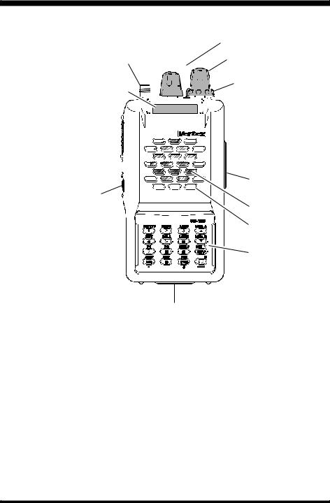
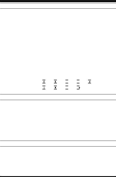
Controls & Connectors
|
VOL/OFF Control BUSY/TX Indicator Lamp |
|||||||||||||||||||||
ANTENNA Jack |
|
|
|
|
|
|
|
|
|
|
|
|
|
|
|
|
|
|
|
|
|
DIAL Rotary Selector |
LCD (Liquid Crystal Display) |
|
|
|
|
|
|
|
|
|
|
|
|
|
|
|
|
|
|
|
|
|
SQL Control |
|
|
|
|
|
|
|
|
|
|
|
|
|
|
|
|
|
|
|
|
|
||
|
|
|
|
|
|
|
|
|
|
|
|
|
|
|
|
|
|
|
||||
|
|
|
|
|
|
|
|
|
|
|
|
|
|
|
|
|
|
|
|
|
|
|
|
|
|
|
|
|
|
|
|
|
|
|
|
|
|
|
|
|
|
|
|
|
|
|
|
|
|
|
|
|
|
|
|
|
|
|
|
|
|
|
|
|
|
|
|
|
|
|
|
|
|
|
|
|
|
|
|
|
|
|
|
|
|
|
|
|
|
|
|
|
|
|
|
|
|
|
|
|
|
|
|
|
|
|
|
|
|
|
|
|
|
|
PTT Button 

 MIC/SP Jack
Monitor (Burst) Button 

EXT DC
LAMP Button
Speaker
Mic
Keypad
Battery Pack Latch
Tone Encoder/Squelch Enabled |
|
|
|
|
|
|
|
|
|
|
|
|
|
|
|
|
|
Digital Coded Squelch |
|||||||||||
|
|
|
|
|
|
|
|
|
|
|
|
|
|
|
|
|
|||||||||||||
Priority Channel Scanning |
|
|
|
|
|
|
|
|
|
|
|
|
|
|
|
|
|
DTMF Memory Mode |
|||||||||||
|
|
|
|
|
|
|
|
|
|
|
|
|
|
|
|
|
|||||||||||||
Repeater Shift |
|
|
|
|
|
|
|
|
|
|
|
|
|
|
|
|
|
|
|
|
Memory Skip |
||||||||
|
|
|
|
|
|
|
|
|
|
|
|
|
|
|
|
|
|
|
|
||||||||||
Memory Mode |
|
|
|
|
|
|
|
|
|
|
|
|
|
|
|
|
|
|
|
|
|
|
|
|
|
|
|
BELL |
|
Memory Number |
|
|
|
|
|
|
|
|
|
|
|
|
|
|
|
|
|
|
|
|
Frequency |
||||||||
|
|
|
|
|
|
|
|
|
|
|
|
|
|
|
|
|
|
|
|
|
|||||||||
or |
|
|
|
|
|
|
|
|
|
|
|
|
|
|
|
|
|
|
|
|
|
|
|||||||
|
|
|
|
|
|
|
|
|
|
|
|
|
|
|
|
||||||||||||||
VFO Selection |
|
|
|
|
|
|
|
|
|
|
|
|
|
|
|
|
|
|
|||||||||||
|
|
|
|
|
|
|
|
|
|
|
|
|
|
|
|
|
|
|
|
|
|
|
|
|
|
|
|
Auto Power OFF Active |
|
|
|
|
|
|
|
|
|
|
|
|
|
|
|
|
|
|
|
|
|
|
|
|
|
|
|
|
|
||
|
|
|
|
|
|
|
|
|
|
|
|
|
|
|
|
|
|
|
|
|
|
|
|
|
|
|
|
||
Alt Key Active |
|
|
|
S- and TX Power Meter |
|
|
|
||||||||||||||||||||||
|
|
|
|
|
|||||||||||||||||||||||||
|
|
|
|
|
|
|
|
|
|
|
|
|
|
|
|
|
|
|
|
|
|
|
|
|
|
|
|
LOCK Feature Active |
|
|
|
|
|
|
|
|
|
|
|
|
|
|
|
|
|
|
|
|
|
|
|
|
|
|
|
|
|
||
|
|
|
|
|
|
|
|
|
|
|
|
|
|
|
|
|
|
|
|
|
|
|
|
|
|
|
|
|
|
LOW Power
2 |
VX-150 OPERATING MANUAL |

Accessories & Options
ACCESSORIES SUPPLIED WITH THE VX-150
FNB-64 |
Ni-Cd Battery Pack (7.2 V, 700 mAh) |
NC-72A/B/C/F/U Battery Chareger
Belt Clip
Antenna
Operating Manual
Warranty Card
|
AVAILABLE OPTIONS FOR YOUR VX-150 |
FNB-V57 |
7.2 V, 1100 mAh Ni-Cd Battery Pack |
FNB-64 |
7.2 V, 700 mAh Ni-Cd Battery Pack |
FBA-25 |
Compact Dry Cell Battery Case for 6 AA-size cells |
CD-16 |
Desktop Rapid Charger (requires CA-24 and PA-23) |
NC-72A |
100 VAC Compact Wall Charger for FNB-64 |
NC-72B |
120 VAC Compact Wall Charger for FNB-64 |
NC-72C |
230-240 VAC Compact Wall Charger for FNB-64 |
NC-72F |
220 VAC Compact Wall Charger for FNB-64 |
NC-72U |
230 VAC Compact Wall Charger for FNB-64 |
NC-73 |
Desktop Rapid Charger |
MH-34B4B |
External Hand Speaker/Microphone |
MH-37A4B |
Earpiece/Microphone |
VC-25 |
VOX Headset |
E-DC-5B |
DC Cable w/Noise Filter |
E-DC-6 |
DC Cable; plug and wire only |
CA-24 |
Charger Sleeve |
PA-23 |
AC Adapter |
CN-3 |
BNC-to-SMA Adapter |
CT-44 |
Microphone Adapter |
YHA-62 |
Rubber flex antenna |
CT-27 |
Cloning Cable |
Availability of accessories may vary: some accessories are supplied as standard per local regulations and requirements, others may be unavailable in some regions. Check with your Yaesu dealer for additions to the above list.
VX-150 OPERATING MANUAL |
3 |
Basic Operation
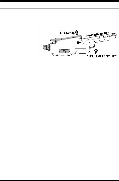
BATTERY PACK INSTALLATION AND REMOVAL
To install the battery, hold the transceiver with your left hand, so your palm is over the speaker and your thumb is on the top of the belt clip. Insert the battery pack into the battery compartment on the back of the radio while tilting the Belt Clip outward, then close the Battery Pack Latch until it locks in place with a “Click.” To remove the battery, turn the radio off and remove any
protective cases. Open the Battery Pack Latch on the bottom of the radio, then
slide the battery downward and out from the radio while unfolding the Belt Clip.
Do not attempt to open any of the rechargeable Ni-Cd packs, as they could explode if accidentally short-circuited.
If the battery has never been used, or its charge is depleted, it may be charged by connecting the NC-72A/B/C/F/U Battery Charger, as shown in the illustration, to the EXT DC jack. If only 12 ~ 16 Volt DC power is available, the optional E-DC-5B (with its cigarette lighter plug) or E-DC-6 DC Adapter may also be used for charging the battery.
The optional FNB-V57 high-capacity battery can not be charged using the NC-72; please use the optional CD-16.
4 |
VX-150 OPERATING MANUAL |
Basic Operation
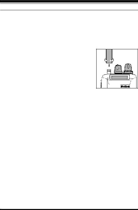
ANTENNA INSTALLATION
The supplied antenna provides good results over the entire frequency range of the transceiver. However, for enhanced coverage in remote areas, an external mobile or base station antenna may prove beneficial.
To install the supplied antenna
Hold the bottom end of the antenna, then screw it onto the mating connector on the transceiver until it is snug. Do not over-tighten by use of extreme force.
Notes:
m Never transmit without having an antenna connected.
m When installing the supplied antenna, never hold the up-
per part of the antenna while screwing it onto the mating connector on the transceiver.
m Remember that a large base-station antenna will have considerably more gain than the supplied rubber flex antenna, and this added gain may degrade the ability of
the VX-150 to resist intermodulation-type interference. The installation of a suitable 144-148 MHz bandpass filter in the coaxial line to a base station will usually eliminate such interference, if encountered.
VX-150 OPERATING MANUAL |
5 |
Basic Operation
SWITCHING POWER ON AND OFF |
• Be sure the battery pack is installed. |
‚ Connect the antenna to the top panel ANTENNA |
jack. |
ƒ Switch on the transceiver by rotating the VOL con- |
trol clockwise out of the click-stop (a momentary |
beep will sound). |
ADJUSTING THE VOLUME LEVEL
Rotate the VOL control (immediately to the right of the Antenna) to set the desired audio level. Clockwise rotation increases the volume level.
SQUELCH SETUP
Set the SQL control fully counterclockwise, rotate the VOL control out of the click-stop and adjust for a comfortable volume on the noise or received signal. The BUSY/TX indicator LED should glow green. If a signal is present, rotate the DIAL selector on the top panel to a channel where only noise is heard.
Adjust the SQL control just to the point where the noise is silenced and the LED is extinguished. If the SQL control is set further clockwise, sensitivity to weak signals will be reduced. Now, whenever a signal reaches the receiver that is strong enough to open the squelch, the indicator will glow green.
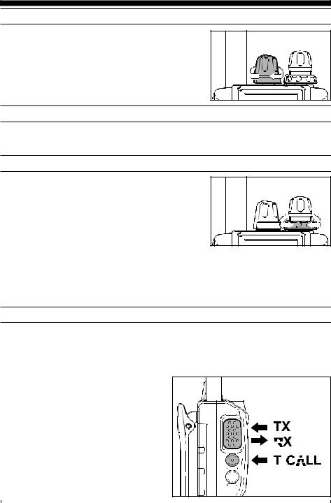
TRANSMITTING
When you wish to transmit, wait until the channel is clear (BUSY/TX lamp off), and squeeze the PTT switch. During transmission the BUSY/TX indicator glows red, and relative transmitter power output is indicated graphically along the bottom of the display. Release the PTT switch to receive.
If using a “B” version (in Europe), press the T-CALL switch (just below the PTT switch) to transmit a 1750 Hz tone to access repeaters that require it.
|
|
|
|
|
|
|
|
|
|
|
|
|
|
|
|
|
|
|
|
|
|
|
|
|
|
|
|
|
|
|
|
|
|
|
|
|
|
|
|
|
|
|
|
|
|
|
|
|
|
|
|
|
|
|
|
|
|
|
|
|
|
|
|
|
|
|
|
|
|
|
|
|
|
|
|
|
|
|
|
|
|
|
|
|
|
|
|
|
|
|
|
|
|
|
|
|
|
|
|
|
|
|
|
|
|
|
|
|
|
|
|
|
|
|
|
|
|
|
|
|
|
|
|
|
|
|
|
|
|
|
|
|
|
|
|
|
|
|
|
|
|
|
|
6 |
VX-150 OPERATING MANUAL |
||||||||||||||||
Basic Operation
FREQUENCY NAVIGATION
Press the [VFO(PRI)] button, if necessary, to select the VFO mode. The VX-150 has two VFOs, labeled “ A” and “ B,” either of which can be used for all of the procedures described in this manual. You can change VFOs with the [VFO(PRI)] button at any time.
There are several ways to tune the VX-150: in selectable channel steps or 1 MHz steps with the [s] / [t] keys or DIAL knob, and direct keypad frequency entry.
Use the DIAL knob to tune the displayed VFO frequency at the current channel step rate. You can also press the [s] / [t] keys momentarily to do this.
To change the MHz range of the VFO, you can press the [F] key followed by an [s] or [t] key (or turn the DIAL knob). Note the beeps when using the [s] / [t] keys when moving up or down. When done, press [F] again, or just wait five seconds.
You can also enter a frequency directly just by keying in the 1 MHz and the kHz digits. If you are using 5 kHz steps enter five digits. Otherwise, just four digits will do. Partial entries can be completed using the [VFO(PRI)] key.
Examples:
To enter 146.5200 MHz, press 

 à
à 

 à
à 

 à
à 

 à
à 


To enter 146.5000 MHz, press 

 à
à 

 à
à 

 à
à 


CHANGING THE TRANSMITTER POWER LEVEL
You can select between a total of three transmitter power levels on your VX-150. The exact power output will vary somewhat, depending on the voltage supplied to the transceiver. With the standard FNB-64 Battery Pack, the power output levels available are:
HIGH: 5 W MID: 2 W LOW: 0.5 W
To change the power level:
•Press the [F/W] key, then immediately press the [3(LOW)] key. ‚Now rotate the DIAL knob to select “ LOW”, “ MID,” or “ HIGH”.
ƒPress the PTT key to save the new setting and exit to normal operation.
CHANGING THE CHANNEL STEPS
To change a frequency step, follow the procedure below:
•Press the [F] key, then immediately press the [0(SET)] key to enter the Set mode. ‚Rotate the DIAL to select Menu Item #6 (“ STEP”).
ƒPress the [F] key to enable modification of the current setting.
„Now rotate the DIAL knob to select 5, 10, 12.5, 15, 20, 25 or 50 kHz steps. …Press the PTT key to save the new setting and exit to normal operation.
VX-150 OPERATING MANUAL |
7 |
Basic Operation
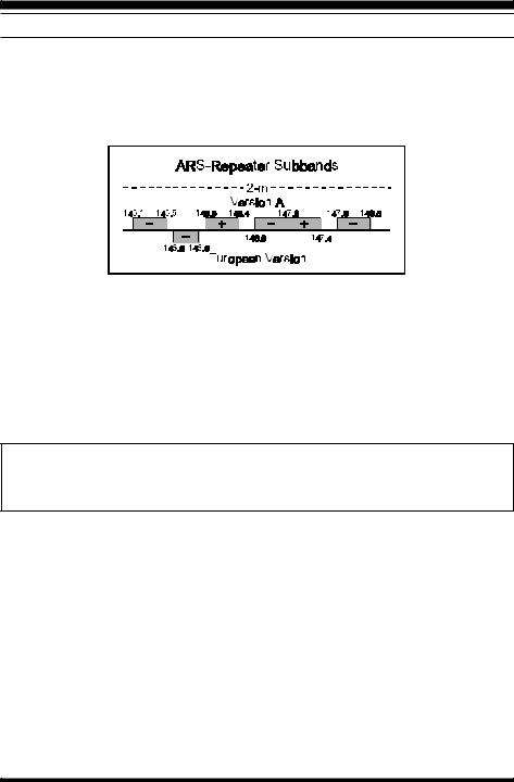
REPEATER OPERATION
The ARS (Automatic Repeater Shift) feature in the VX-150 provides repeater shift of the transmit frequency whenever you are tuned to a standard repeater subband (see diagram below). When enabled, a small “ – ” or “ +” will be displayed in the upper left-hand corner of the display, signifying that repeater shift is active, and closing the push-to-talk switch changes the display to the (shifted) transmit frequency.
Automatic Repeater Shift (ARS)
To re-enable ARS:
• Press the [F] key, then immediately press the [0(SET)] key to enter the Set mode. ‚ Rotate the DIAL to select Menu Item #2 (“ ARS”).
ƒ Press the [F] key to enable modification of the current setting.
„ Now rotate the DIAL to select “ON” (to enable Automatic Repeater Shift). … Press the PTT key to save the new setting and exit to normal operation.
Tone Burst
For repeaters using 1750-Hz burst tone access, you can configure the switch below the PTT to send the access tone when this switch is pressed. See page 14 for details.
Manual Repeater Shift Activation
When a repeater shift is active, either “ – ” or “ +” appears in the display. If neither appears when tuned to a repeater output frequency, you can activate the shift manually:
• Press the [F] key, then immediately press the [0(SET)] key to enter the Set mode. ‚ Rotate the DIAL to select Menu Item #3 (“ RPT”).
ƒ Press the [F] key to enable modification of the current setting.
„ Rotate the DIAL to select the desired repeater shift direction (-RPT, +RPT or SIMP). … Press the PTT key to save the new setting and exit to normal operation.
8 |
VX-150 OPERATING MANUAL |
Basic Operation
Setting repeater Tx Offset
Although you should keep the repeater offset programmed to that used in your area, you can change the default repeater offset for special applications:
•Press the [F] key, then immediately press the [0(SET)] key to enter the Set mode. ‚Rotate the DIAL to select Menu Item #4 (“ SHIFT”).
ƒPress the [F] key to enable modification of the current setting.
„Rotate the DIAL to select the new shift offset frequency (selectable in 50-kHz increments only).
…Press the PTT key to save the new setting and exit to normal operation.
Checking the Repeater Uplink (Input) Frequency
It often is helpful to be able to check the uplink (input) frequency of a repeater, to see if the calling station is within direct (“Simplex”) range.
To do this, just press the [REV(HM)] key momentarily. If Menu Item #20 (“ REV/HM”) has been set to “ HM,” you may press the [F] key, and then [REV(HM)] key. To return to the normal uplink/downlink frequency relationship, repeat this step.
KEYBOARD LOCKING
In order to prevent accidental frequency change or inadvertent transmission, various aspects of the VX-150’s keys and switches may be locked out. The possible lockout combinations are:
KEY: |
Just the front panel keys are locked out |
DIAL: |
Just the top panel DIAL is locked out |
K + D (KEY + DIAL) : Both the DIAL and Keys are locked out |
|
PTT: |
The PTT switch is locked (TX not possible) |
K + P (KEY + PTT) : Both the keys and PTT switch are locked out D + P (DIAL + PTT) : Both the DIAL and PTT switch are locked out ALL: All of the above are locked out
To lock out some or all of the keys:
•Press the [F] key, then press the [0(SET)] key to enter the Set mode. ‚Rotate the DIAL to select Menu Item #32 (“ LK MODE”).
ƒPress the [F] key to enable setting of the Lock mode (which defines which keys/functions are to be locked out).
„Rotate the DIAL to choose between one of the locking schemes as outlined above.
…Once you have made your selection, press the PTT key momentarily to save the new setting and resume normal operation.
†To activate the locking feature, press the [F] key, then press the [6(LOCK)] key. The “  ” icon will appear on the LCD. To cancel keyboard locking, again press the [F] key, followed by the [6(LOCK)] key.
VX-150 OPERATING MANUAL |
9 |

Advanced Operation
VFO SPLIT MODE
For working on repeaters with odd splits, or communicating with astronauts on orbiting space vehicles, it may be necessary to use non-standard splits between the receive and transmit frequency. If the application is infrequent enough not to warrant the dedication of a memory channel for this purpose, the “VFO Split” mode may be used. Here is the procedure:
•Press the [VFO(PRI)] key, as needed, to select VFO-A. Set VFO-A for the receiving frequency (for example, 144.950 MHz).
‚Now press the [VFO(PRI)] key, and set VFO-B for the desired transmit frequency (e.g. 144.750 MHz).
ƒPress the [VFO(DW)SC] key once more to re-establish VFO-A as the “Main” (receive) VFO.
„ Press the [F] key, then press the [0(SET)] key, to enter the Set mode. … Rotate the DIAL to select Menu #5 (“ V-SPLIT”).
† Press the [F] key, then rotate the DIAL to set this function ON.
‡ Press the PTT key once to save the new setting and exit to normal operation.
ˆYou will now be operating in a Split mode. When you press the PTT key to transmit, you will observe that VFO-A and VFO-B will reverse positions.The VFO selection indicator “ b” will blinks while the transceiver is transmitting, this means that the VFO Split feature is now activated.
‰If you need to modify the VFO-B (transmit) frequency (for Doppler Shift correction, etc.), just press the [VFO(PRI)] key, then make the necessary change, then press [VFO(PRI)] key once more to restore VFO-A to the “receive VFO” position.
ŠWhen you have finished with Split operation, re-enter the Set mode, and set Menu #5 to OFF.
A split frequency pair set up via the VFO Split feature cannot be stored directly into memory. You can, however, store odd frequency pairs using a different (slightly simpler) procedure. See page 18.
RECEIVE BATTERY SAVER SETUP
An important feature of the VX-150 is its Receive Battery Saver, which “puts the radio to sleep” for a time interval, periodically “waking it up” to check for activity. If somebody is talking on the channel, the VX-150 will remain in the “active” mode, then resume its “sleep” cycles. This feature significantly reduces quiescent battery drain, and you may change the amount of “sleep” time between activity checks using the Menu System:
• Press the [F] key, then press the [0(SET)] key to enter the Set mode. ‚ Rotate the DIAL to select Menu Item #9 (“ RX SAVE”).
ƒ Press the [F] key to enable adjustment of this Menu item.
10 |
VX-150 OPERATING MANUAL |

Advanced Operation
„Rotate the DIAL to select the desired “Sleep” duration. The selections available are 200 ms, 300 ms, 500 ms, 1 second, and 2 seconds, or OFF. The default value is 200 ms.
…When you have made your selection, press the PTT key to save the new setting and exit to normal operation.
When you are operating on Packet, switch the Receive Battery Saver OFF, as the sleep cycle may “collide” with the beginning of an incoming Packet transmission, causing your TNC not to receive the full data burst. Likewise, during voice operation, part of the first word of an incoming transmission may be cut off during (normal) Battery Saver operation.
TX BATTERY SAVER
The VX-150 also includes a useful Transmit Battery Saver, which will automatically lower the power output level when the last signal received was very strong. With the Transmit Battery Saver, the automatic selection of Low Power operation conserves battery drain significantly.
To activate the Transmit Battery Saver:
•Press the [F] key, then press the [0(SET)] key to enter the Set mode. ‚Rotate the DIAL to select Menu Item #10 (“ TX SAVE”).
ƒPress the [F] key to enable adjustment of this Menu item.
„Rotate the DIAL so as to select ON (thus activating the Transmit Battery Saver).
…When you have completed your selection, press the PTT key to save the new setting and exit to normal operation.
KEYPAD/LCD ILLUMINATION
Your VX-150 includes a reddish illumination lamp which aids in nighttime operation. Three options for activating the lamp are provided:
KEY : Pressing any key (except PTT) causes the lamp to provide illumination for 5 seconds, after which the lamp will automatically shut off.
5SEC : Pressing the LAMP switch momentarily causes the lamp to provide illumination for 5 seconds, after which the lamp will automatically shut off.
TOGGLE : Pressing the LAMP switch momentarily “Toggles” the lamp on and off. The lamp will stay illuminated until you press the LAMP switch once more.
Here is the procedure for setting up the Lamp mode:
•Press the [F] key, then immediately press the [0(SET)] key to enter the Set mode. ‚Now rotate the DIAL to select Menu Item #21 (“ LMP MOD”).
ƒPress the [F] key to enable modification of the current setting.
„Next, rotate the DIAL to select one of the three modes described above.
…When you have made your choice, press the PTT key to save the new setting for Menu Item #21. The transceiver will now return to normal operation.
VX-150 OPERATING MANUAL |
11 |

Advanced Operation
AUTOMATIC POWER-OFF (APO) FEATURE
The APO feature helps conserve battery life by automatically turning the radio off after a user-defined period of time within which there has been no dial or key activity. The available selections for the time before power-off are 0.5/1/3/5/8 hours, as well as APO Off. The default condition for the APO is OFF, and here is the procedure for activating it:
• Press the [F] key, then press the [0(SET)] key to enter the Set mode. ‚ Rotate the DIAL to select Menu Item #11 (“ APO”).
ƒ Press the [F] key to enable adjustment of this Menu item.
„Rotate the DIAL to select the desired time period after which the radio will automatically shut down.
…Once you have made your selection, press the PTT key to save the new setting and exit to normal operation.
CHECKING THE BATTERY VOLTAGE
The VX-150 is capable of measuring the current battery voltage.
• Press the [F] key, then press the [0(SET)] key to enter the Set mode. ‚ Rotate the DIAL to select Menu Item #37 (“ BATT”).
ƒ Press the [F] key to check the battery voltage.
„ To return to normal operation, press the [F] key, then press the PTT.
DISABLING THE BUSY/TX LED
Further battery conservation may be accomplished by disabling the BUSY/TX LED. Use the following procedure:
• Press the [F] key, then press the [0(SET)] key to enter the Set mode. ‚ Rotate the DIAL to select Menu Item #12 (“ TRX LED”).
ƒ Press the [F] key to enable adjustment of this Menu item.
„ Rotate the DIAL to set this Menu item to OFF (thus disabling the BUSY/TX LED). … Press the PTT key to save the new setting and exit to normal operation.
BUSY CHANNEL LOCK-OUT (BCLO)
The BCLO feature prevents the radio’s transmitter from being activated if a signal strong enough to break through the “Noise” squelch is present. The default setting for the BCLO is OFF, and here is how to change that setting:
• Press the [F] key, then press the [0(SET)] key to enter the Set mode. ‚ Rotate the DIAL to select Menu Item #23 (“ BCLO”).
ƒ Press the [F] key to enable adjustment of this Menu item.
„ Rotate the DIAL to set the BCLO feature to the “ON” position.
… Press the PTT key to save the new setting and resume normal operation.
12 |
VX-150 OPERATING MANUAL |
 Loading...