

DIGITAL INDICATORS DIGITAL INDICATORS
Instruction manual
This instruction applies for:
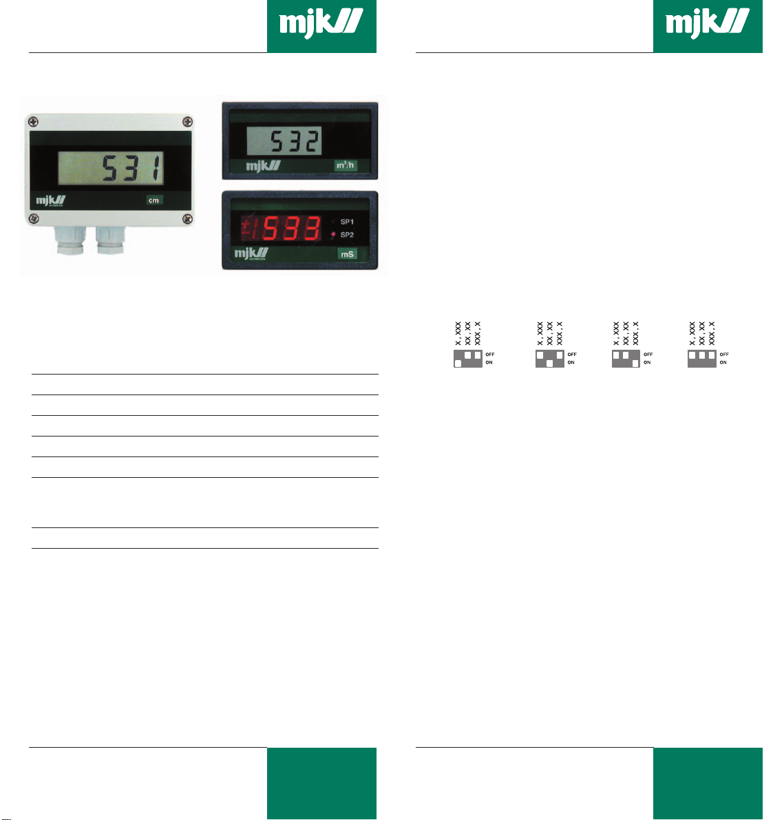
- Loop powered indicator 531 for field mounting
- Loop powered indicator 532 for panel mounting
- 230 V AC powered indicator 533 for panel mounting
General specifications
Indicator type: 531 532 533
Mounting: Field Panel Panel
Enclosure: IP65 IP22 IP22
Temperature range: -20 °C … + 50 °C
Resolution: ± 1 count
Adjustments:
- 0 point, readout - 1000 … 0 … + 1000
- Span readout/mA 12…125 20 … 200 12…125
Linearity: ± 1%
Adjustment
The indicators have a built-in signal generator for adjustment
and readout of limit values eliminating the need for external
instruments. When adjusting, the indicator must be connected
to an active measuring signal. The measuring signal has no
influence on the adjustment.
When adjusting decimal separator, 0-point and span, only the
switches for decimal separator and one of the switches for
adjustment of 0-point or span can be in the ON position.
Setting of decimal separator position
3 switches for setting of the decimal separator position is found
on the back of the indicator. The following four settings can be
selected:
8.8.8.88.8.8.88.8.8.88.8.8.8
Adjustment of 0-point
The optional values for 0-point is shown in
section "Specifications".
Set the switch "MEASURE" in "OFF" position and the "4 mA
READING" in "ON" position. Set the 0-point with the potentiometer to "4 mA READING". Set the switch "MEASURE" back in
"OFF" position, and the instrument is now ready for use.
Measuring units
Digital indicators are applied for readout of level, flow, pressure,
ph etc. The far most used measuring values are pre-printed as
symbols on the enclosed green sheet. The indicators are
supplied with a transparent panel where symbols from the preprinted sheet can be put in. Use white transfer letters or a white
pen if your symbol is not enclosed.
On type 531, the label can easily be put in by loosening the
display insertion from the lid. On type 532 and 533 the front
frame can be dismantled. Push carefully on the terminal plugs
on the back of the instrument to push out the front glass.
MJK Automation A/S
M531-2-3GB0504
1
Byageren 7
DK-2850 Nærum
Denmark
mjk@mjk.com
www.mjk.com
Adjustment of span
The optional values for span is shown in section
"Specifications".
Set the switch "MEASURE" in "OFF" position and the "20 mA
READING" in "ON" position. Set the 0-point with the potentiometer to "20 mA READING". Set the switch "MEASURE" back
in "OFF" position, and the instrument is now ready for use.
MJK Automation A/S
M531-2-3GB0504
2
Byageren 7
DK-2850 Nærum
Denmark
Tel.: +45 45 56 06 56
Fax: +45 45 56 06 46
DIGITAL INDICATORS DIGITAL INDICATORS
Field indicator type 531, 4-20mA loop powered
General
Field indicator 531 is supplied either in IP65 enclosure or as a
display insertion for mounting in a connection box for a pressure, pH or temperature transmitter. The indicator is loop
powered from the 4-20mA signal with a maximum voltage drop
of 3,5 V.
Specifications
Item number, complete instrument: 200125
Item number, display insertion: 200126
Mounting and enclosure: Field, IP65
Supply: 4-20 mA
Voltage drop: Max: 3,5 V
Dimensions: 80 X 120 X 56 mm (HxWxD)
Switch settings
Decimal point
Measurement
4mA display
20mA display
{
4 mA setting
1
2
3
4
5
6
off on
n
n
n
20 mA setting
off on
n
n
n
Measurement
off on
n
n
n
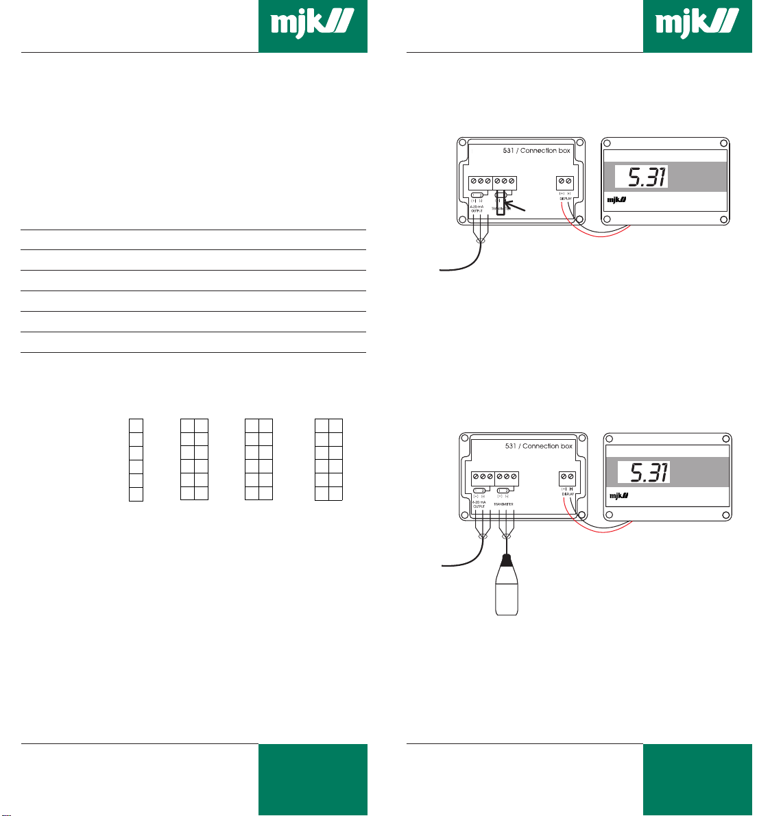
Field indicator type 531 for active 4-20 mA signal
The active 4-20 mA signal is connected to the leftmost
terminals as shown below:
Active
4-20 mA signal
531 Display insert
Note: A jumper must be mounted in terminal 1 and two in
the middle terminal block !
Field indicator type 531 in series (as junction box)
Mount the cables as shown below:
Note: No jumpers must be present.
Connection
Electrical connection is made as shown on the following diagrams.
The display insert is connected to the two terminals on the PCB
in the junction box. (Red to + and black to -). A Zener diode
ensures the current loop if the display insert is disconnected.
Note: A separate 531 display insert can be mounted on an
existing junction box. According to the version, the
PCB can be mounted with one or two solder bridges.
MJK Automation A/S
M531-2-3GB0504
3
Byageren 7
DK-2850 Nærum
Denmark
mjk@mjk.com
www.mjk.com
Active
4-20 mA signal
M531-2-3GB0504
Pressure
transmitter
531 Display insert
MJK Automation A/S
Byageren 7
4
DK-2850 Nærum
Denmark
Tel.: +45 45 56 06 56
Fax: +45 45 56 06 46

DIGITAL INDICATORS DIGITAL INDICATORS
Panel Indicator type 532, 4-20 mA loop powered
General
Indicator type 532 is designed for panel mounting. The indicator is
serial connected in a 4-20mA current loop for indication of process
values such as level, pressure, flow, pH, temperature etc.
The indicator is loop powered from 4-20 mA signal with max.
voltage drop on 3,5 V.
The display can be background illuminated by connection to a
separate voltage source.
Specifications
Part number: 200120
Mounting and enclosure: Panel, IP 21
Supply: 4-20 mA
Voltage drop: Max. 3,5 V
Dimensions: (frame) 48 x 96 x 66 mm (H x W x D)
Panel cut out: 43 x 93 (-0, +1) mm (H x W)
Switch settings
4 mA setting
on off
1
2
n
3
4
5
6
Mounting
The indicator is placed in the panel cut-out and fastened with
the enclosed brackets.
Connection
Connect the terminals marked on the backside of the instrument 4 - 20 mA signal - + and 4 - 2 mA signal in series with 4 20 mA signal. The back light is supplied separately with 12 - 35
V AC/DC on the terminals marked "Display back light".
n
n
20 mA setting
on off
n
n
n
Measurement
on off
Measurement
n
4mA readout
n
20mA readout
n
Decimal position
}
Panel indicator type 532, connected to pressure transmitter
and power supply, type 515 or PLC.
Panel indicator type 533, 230 V AC
General
Indicator type 532 is designed for panel mounting. The indicator
is supplied with 2 potential free limit relays, which can be
adjusted throughout the whole measuring range. Like all other
indicators, 0-point and span can be set to any value within the
measuring range. Se page 2.
Specifications
Part no: 200130
Mounting and enclosure: Panel, IP 21
Supply: 230 / 115 V AC
Fuse: 0,063 A MT (550031)
Transmitter supply: 24 V DC / 100 mA
Signal: 2- or 3-wire, 0 - 20 / 4 - 20 mA
Limit relays: 0 - 100 % of measuring range
Relay load: 48 V AC, 1A
Front dimensions: 48 x 96 x 130 mm (H x W x D)
Panel cut-out: 43 x 93 (-0, +1) mm (H x W)
M531-2-3GB0504
MJK Automation A/S
Byageren 7
5
DK-2850 Nærum
Denmark
mjk@mjk.com
www.mjk.com
M531-2-3GB0504
6
MJK Automation A/S
Byageren 7
DK-2850 Nærum
Denmark
Tel.: +45 45 56 06 56
Fax: +45 45 56 06 46

DIGITAL INDICATORS DIGITAL INDICATORS
Switch settings
Decimal poin
{
SP2 (low value)
SP1 (high value)
4 mA display
20 mA display
Measurement
Internal
switches
0 (4) mA setting
off on
8
7
6
5
4
3
2
1
3
2
0-20
1
n
n
n
n
o
n
o
4-20
20 mA setting
off on
n
n
n
n
High setpoint
off on
n
NC NO
n
n
n
n
n
Relay high
o
o
Low setpoint
off on
Measurement
n
n
n
n
n
Relay low Input
NC NO
o
o
off on
n
n
n
n
n
Set point adjustment
Set the switch SP1 (high value) or SP 2 (low value) to the ON
position, and adjust the potentiometer until due limit value is
displayed. Remember that only one switch can be in the
position ON. The limit relays have a fixed differential value of
approx. 5 %. SP1 (high limit) is activated on the limit value and
deactivates below the set limit value. SP2 (low limit) is also
activated on the set limit value but is deactivated above the set
limit value.
Adjustment of relay function (NO/NC)
and signal range 0/4 - 20mA
Limit relay function is set to NO (normally open) or NC (normally
closed) by 2 switches that are accessible when the back panel
is removed. Relays are factory set to NO (the relay switch
closes when the limit is exceeded).
A third switch change between 0 - 20 mA and 4 - 20 mA signal.
The instrument is factory set to 4 - 20 mA.
The indicator is set in the panel cut-out and fastened with the
enclosed brackets.
Connection
2-wire active 4 - 0 mA signal.
Indicator 533 is
connected to a 2-wire,
4 - 20 mA pressure
transmitter.
3-wire active 4 - 20 mA signal.
Sonolev
Indicator 533
connected to a
3-wire, 4 - 20 mA
signal output
from an MJK
7030 ultrasonic
transmitter.
3-wire passive 0 - 20 / 4 - 20 mA signal
Indicator 533
connected to a
pH transmitter.
M531-2-3GB0504
MJK Automation A/S
Byageren 7
7
DK-2850 Nærum
Denmark
mjk@mjk.com
www.mjk.com
M531-2-3GB0504
8
MJK Automation A/S
Byageren 7
DK-2850 Nærum
Denmark
Tel.: +45 45 56 06 56
Fax: +45 45 56 06 46
 Loading...