


Whirlpool ACM 623/LX, ACM 730/IX, ACM 623/NE, ACM 703/NE, ACM 721/NE INSTALLATION manual
...
 IMPORTANT SAFETY INFORMATION
This manual contains important information regarding safety, the use and maintenance of your new hob. Read the manual carefully and keep it in an easily accessible place for future consultation.
Precautions and Advice
1.Disposal of packaging materials: dispose of the various packing materials responsibly, in full compliance with local authority regulations governing waste disposal.
2.This induction hob is designed solely for use as a domestic appliance. No other type of use is permitted. The manufacturer declines all responsibility for inappropriate use.
3.The appliance is not intended for use by persons (children included) with physical, sensory or mental impairment or without experience and knowledge of the appliance, unless supervised or previously instructed in its use by those responsible for their safety.
4.The cooking zones become extremely hot during use: be careful and keep children away from the appliance to avoid the risk of scalding or burns.
5.The letter “H” will appear on the control panel display to indicate “residual heat” in the corresponding cooking zone: the temperature of the cooking zone is above 60 °C: do not touch the cooking zone or
place any object on it while the letter “H” remains lit.
6.If the surface of the hob should become damaged (cracked or broken glass), do not use the appliance and call the After-sales Service immediately.
7.Any repairs or work on the appliance must be carried out by a qualified technician.
8.This hob is equipped with a thermoprotector to prevent the risk of its internal circuits being damaged by high temperatures from external heat sources (e.g. an undercounter oven). If the temperature of the electronic circuits exceeds the safety threshold, the thermoprotector activates, automatically switching off the hob. The display shows an error message
(see. section “Troubleshooting Guide”). When the temperature returns to within normal levels the hob is able to be switched on again.
Recommended diameters of pot bottoms
9.Make sure the cooking zones and the bottoms of pots are dry before use.
10.Do not place metal objects such as kitchen utensils (knives, forks, spoons, …), lids or other similar items on the cooking zones as they can become very hot.
11.Be extremely vigilant when cooking food with boiling oil or fat since these can catch fire. In the event of oil catching fire, never attempt to put it out with water: switch the hob off and cover the pot immediately with a lid; leave the pot on the cooking zone to cool down. Dispose of the oil in compliance with current regulations.
12.When you finish cooking, press button  .
.
Before use
|
Important: The induction cooking zones |
|
will not switch on if pots and pans are not of |
|
the correct dimensions. |
|
Only use pots bearing the symbol |
|
“INDUCTION SYSTEM” (See figure |
|
opposite). |
Before switching the hob on, position the pot on the |
|
desired cooking zone. |
|
Existing pots and pans: |
|
OK |
NO |
Use a magnet to check whether pots or pans are suitable for use on the induction hob: pots are unsuitable if they cannot be magnetically detected.
1.Ensure pots have a smooth bottom, otherwise they may scratch the hob's glass ceramic surface. Check dishes.
2.Do not use empty pots on the hob, especially enamelled or aluminium ones. This could result in damage to both the glass ceramic surface and the bottom of the pots.
3.Never place hot pots or pans on the hob's control panel. This could result in damage.
|
Ø |
|
Ø |
M |
Ø |
|
Ø |
|
XL 26 cm |
17 cm |
26 cm |
18 cm |
12 cm |
18 cm |
|||
L |
Ø |
|
Ø |
S |
Ø |
|
Ø |
|
21 cm |
14 cm |
21 cm |
14.5 cm |
9 cm |
14.5 cm |
|||
|
|
|||||||
3


 INSTALLATION and ELECTRICAL CONNECTION
Installation must be carried out by a qualified electrician who is fully aware of current safety and installation regulations. The manufacturer declines all liability for injury to persons or animals and for damage to property resulting from failure to observe the regulations provided in this chapter.
Electrical connections
•Hob electrical connection must be made before connecting the appliance to the electricity supply.
•Electrical connection must be carried out in compliance with the regulations of the local electric utility company.
•Make sure that the voltage indicated on the rating plate on the underside of the appliance corresponds to the domestic power supply voltage.
•Regulations require that the appliance is earthed: use conductors (including the earth conductor) of the appropriate size only.
•For electrical connection, use an H05 RR-F type cable as specified in the table “Power supply voltage”.
The power supply cable must be long enough to allow the hob to be removed from the worktop and must be positioned so as to avoid damage or overheating caused by contact with
the base of the hob itself. Do not use extension leads.
Power supply voltage
Wires |
Amount x size |
|||||||||
230V |
~ + |
|
|
|
|
|
|
|
|
3 X 4 mm2 |
|
|
|
|
|
|
|
|
|||
230-240V ~ + |
|
|
|
3 X 4 mm2 (Australia only) |
||||||
|
|
|||||||||
230V |
3 ~ + |
|
|
|
|
|
|
|
4 X 1.5 mm2 |
|
|
|
|
|
|
|
|
||||
400V |
3N ~ + |
|
|
5 X 1.5 mm2 |
||||||
|
||||||||||
400V |
2N ~ + |
|
|
4 x 1.5 mm2 |
||||||
|
||||||||||
If the hob already has a power cable, follow the instructions given on the label attached to the cable.
Connect the appliance to the electricity supply by means of an all-pole disconnect switch with minimum contact gap of 3 mm.
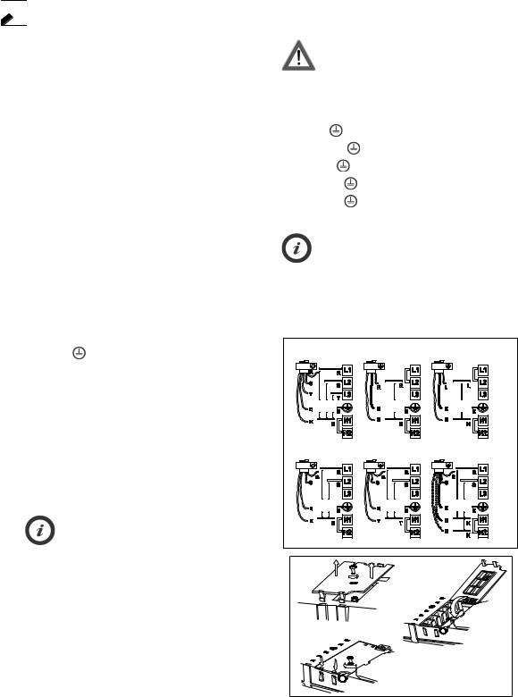
Connecting to the terminal board
Connect the yellow/green earth wire to the terminal with
the symbol |
|
. This wire must be longer than the other |
wires. |
|
|
1.Remove the terminal block cover (A), undoing the screw and inserting the cover in the terminal block hinge (B).
2.Strip approx. 70 mm of sheath from the power supply cable.
3.Strip approx. 10 mm of sheath from the wires. Insert the power supply cable into the cable clamp and connect the wires to the terminal board as indicated in the diagram next to the terminal board itself.
4.Secure the power cable with the cable clamp.
5.Close the cover (C) and screw it on the terminal block with the removed screw - point (1).
Each time the cooktop is connected to the mains it carries out an automatic check which lasts several seconds.
400V 3N ~ |
230V ~ |
230-240V~FOR AU ONLY |
||||
230V~FOR UK ONLY |
||||||
230V |
230V |
230V |
|
230V |
|
230V |
400V 2N ~ |
230V 3~ |
400V 2N~ |
||||
ONLY FOR BELGIUM |
FOR NL ONLY |
|||||
230V |
230V |
230V |
230V |
230V |
230V |
|
A
B
C
4

Installation and fixing
The installer is responsible for any damage or injury resulting from incorrect installation.
To guarantee correct operation, the appliance must be installed on a perfectly flat surface.
The worktop must be -20 50mm thick.
If necessary, cut the kitchen unit and worktop to fit before installing the hob. Clean the cutout of any chips that could compromise appliance operation.
For cut-out dimensions, see the figure below.
Dimensions |
|
580 |
|
|
|
|
770 |
|
|
|
in mm |
|
|
|
|
|
510 |
|
|||
|
510 |
|
|
|
|
|
|
|||
|
|
|
|
|
|
|
|
|
|
|
|
|
|
+1 |
|
|
|
|
+1 |
||
|
|
|
|
|
|
|
52 |
0 |
||
|
|
|
52 |
0 |
|
|
|
|
||
|
483 |
|
|
|
|
|
|
|||
|
|
|
483 |
|
|
|
||||
|
|
|
|
|
|
|
||||
|
|
|
|
|
|
|
|
|||
|
|
553 |
|
|
|
742 |
|
|
||
|
|
|
|
|
|
|
|
|
||
min. 50 |
|
R min. 6.5 |
min. 50 |
|
|
R min. 6.5 |
||||
|
|
|
max. 8 |
|
|
|
|
max. 8 |
||
|
|
|
|
|
|
|
|
|
||
+2 |
|
|
|
+2 |
|
|
|
|
||
490 |
0 |
+2 |
|
|
+2 |
|
||||
|
|
490 |
0 |
|
|
|||||
|
|
|
|
0 |
|
|||||
|
|
560 |
0 |
|
|
|
750 |
|
||
|
|
|
|
|
|
|
|
|
||
For flush mounted installation or setting into a marble worktop, contact the After-sales Service for the installation kit and necessary instructions.
•4812 310 19277 Installation kit for marble worktop.
•4801 211 00112 Installation kit for flush fitted worktop.
To guarantee correct operation, the appliance must be installed on a perfectly flat surface.
The worktop must be 20-50 mm thick.
If necessary, cut the kitchen unit and worktop to fit before installing the hob. Clean the cutout of any remaining dust
Assembly 
1.Position the clips (A) in the spaces provided on the hob trim (fig. 3) if not already positioned.
2.Measure the centre point of the vertical sides of the cut-out (fig. 1)
3.Fit the brackets (C) in the centre of the vertical sides, aligning the upper edge of the brackets so that they are flush with the worktop surface (fig. 2).
that could compromise appliance operation.
For the distance between the underside of the induction hob and the kitchen unit (or separating panel), observe the dimensions given in the figure at the side. If a column unit is installed adjacent to the hob, leave a distance of at least 100 mm from the edge of the hob.
min. 5
min. 20
min. 5
4.Fix the brackets with the 4 screws supplied (B) using the holes provided.
5.Insert the hob in the cutout, making sure the clips (A)
are secured in the spaces provided (fig. 4).
|
C |
|
B |
fig. 1 |
fig. 2 |
5
 Loading...