


ACM 935/1 WH

4
INSTRUCTIONS FOR USE
INSTALLATION INSTRUCTIONS
USE AND MAINTENANCE
BEFORE USING THE APPLIANCE
PRECAUTIONS AND GENERAL ADVICE
OVEN ACCESSORIES
CLEANING AND MAINTENANCE
TROUBLESHOOTING GUIDE
AFTER-SALES SERVICE
For best use of the oven, carefully read the operating instructions and keep them for future
consultation.
5
INSTALLATION INSTRUCTIONS
ELECTRICAL CONNECTION
This appliance must be earthed by law. Before connecting
the appliance to the electrical supply, check that the earth
system in your house is working correctly.
Check that unit voltage and power, marked on the rating plate
applied on the appliance, are correct for the supply. It is necessary
that the feeding network is protected by a powerful switch able
to disconnect completely the network with a contacts separation
of at least 3 mm. Be sure that the earth wire green/yellow is
not interrupted by the switch.
WARNING: THIS APPLIANCE MUST BE EARTHED
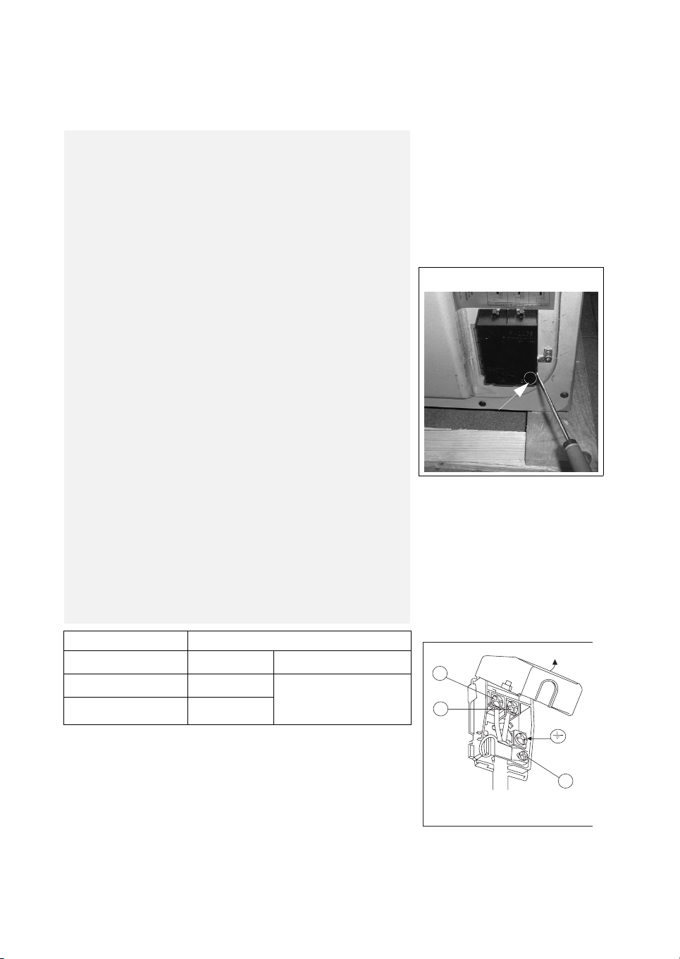
Connecting the mains cable
Open the mains terminal block cover as shown, unscrew the
cable clamp “A” and unscrew (not fully) the screws in the mains
terminal block which secure the three wires of the mains cable.
Fit the cable and refit the cable clamp “A” (fig. 1 ).
IMPORTANT
The wires in the mains lead are coloured in accordance with the
following code:
GREEN & YELLOW ............................................ EARTH
BLUE.................................................................... NEUTRAL
BROWN............................................................... LIVE
The supply cable must not come into contact with any
component the temperature of which exceeds the ambient
temperature by 50°C.
Easy access to the plug or the switch is ensured once the
appliance is installed.
Ensured that there is sufficient cable allowed for any subsequent
removal of the unit.
In order to avoid hazard, any electrical work performed on this
equipment or its associated wiring should only be done by persons
authorised by the manifacture or similary qualified persons.
Terminal block cover
A
Appliance type Single-phase alimentation 230 V~
All gas
3 x 1 mm
2
Ty p e o f c ab le
All gas + elett. grill
3 x 1,5 mm
2
Rubber H05 RR-F
or
Rubber H05 VV-F
All gas + hotplates
3 x 1,5 mm
2
L
N
A
Fig. 1
6
This appliance is in Class 1.
The appliance must be used with the gas specified on the appliance data plate located on the
back cover (see details given on the product).
Installation and maintenance of the appliance must be carried out by a qualified technician in
compliance with the conditions established in the applicable regulation documents and the
ethical codes.
Gas connection
The gas supply system must comply with current local
regulations.
The cookers with support for cylinders are regulated to be
used with LPG.
The support cylinder space is 620 mm high and 325 mm
wide and can contain standard cylinders of 10 kg.
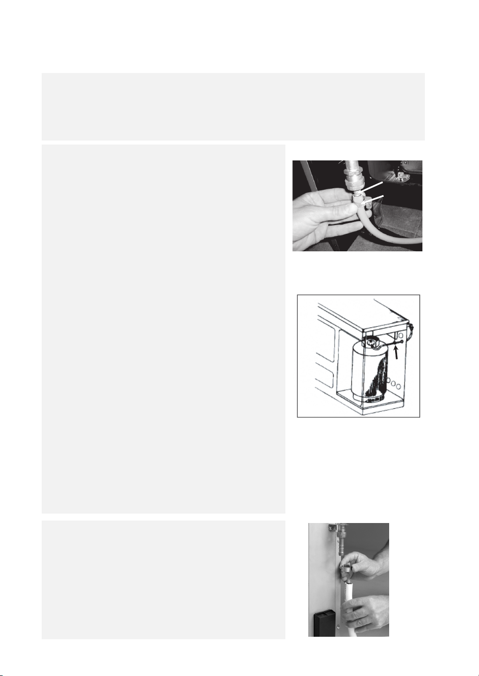
Provide the cylinder with a gas pressure reducer (according to
UNI-CIG 7432).
Connect it to the reducer A using a hosepipe of 8 mm (Fig.2).
The hosepipe MUST be connected to the outlet connector and
secured using a hose metal clamp B (Fig.2).
Arrange the cylinder in the special space (Fig.3).
IMPORTANT: follow these guidelines:
1. The flexible hosepipe shall be from 400 mm up to 800 mm
long and conform to the standards.
2. The cylinder support of the reducer shall be faced to the right
side of the cylinder support space.
3. The hosepipe connection of the reducer/cooker cylinder
supports shall be carried out as indicated in fig. 3 (C), i.e.:
entering the support place upright and coming out from the
cooker by the special back hole. For a fasten operation use
clamps conform to the standards.
4. Arrange the cylinder in the special space, not in contact with
the oven wall.
5. During the cylinder change, do not remove the tube from its
crossing.
IMPORTANT:
The hosepipe shall not present narrowing and be far from heat
sources, especially the back of the oven.
After connection, check that the pipes are properly sealed, using
a soapy water solution on the joints.
The flexible hosepipe shall be visible and never cross from one
side of the appliance to the other.
C
A
B
Fig. 3
Fig. 2
Natural gas
Use outlet connector GN for natural gas or a propane-air
mixture.
The rubber hose must be connected to the outlet connector and
secured using hose clamp A (Fig. 4).
Important: Close the gas supply tap before carrying out any
maintenance operation.
Connection details: see the specific regulations for your country.
A
Fig. 4
7
Gas adjustments
Use pressure regulators that are suitable for the gas
pressure values indicated in the Product Description Sheet
supplied separately.
If the appliance is arranged for a type of gas different from that
available, it is necessary to change the injectors, adjust the
minimum flame, change the outlet connector.
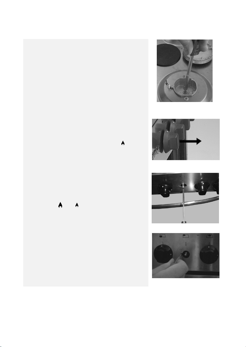
Carry out the following operations to change the hob injectors:
remove the grills; remove the burners, the burner caps
(see Fig. 5); change the injector and replace it with one suitable
for the new type of gas (see table in separate Product Sheet).
Replace the gas calibration label with the new label included in the
injector bag.
Refit everything in reverse order, making sure to correctly fit the
burner cap on the burner.
Minimum for hob taps
To adjust the minimum flame, proceed as follows:
• Light the burner and turn the knob to minimum ; remove
the tap knob (Fig. 6). Insert a small screwdriver next to the tap
pin (Fig. 7).
Attention: in taps with security valve, the minimum adjusting
screws is placed outside the rod tap (fig. 7A).
Turn the adjustment screw anticlockwise to increase the flame,
or clockwise to decrease it. Adjustment is correct when the flame
is approx. 3 - 4 mm.
The adjustment screw must be completely screwed down for
butane/propane gas.
Make sure the flame does not go out when switching suddenly
from high to low flame and vice versa.
Refit the knob.
Fig. 6
Fig. 5
Fig. 7
Fig. 7A
8
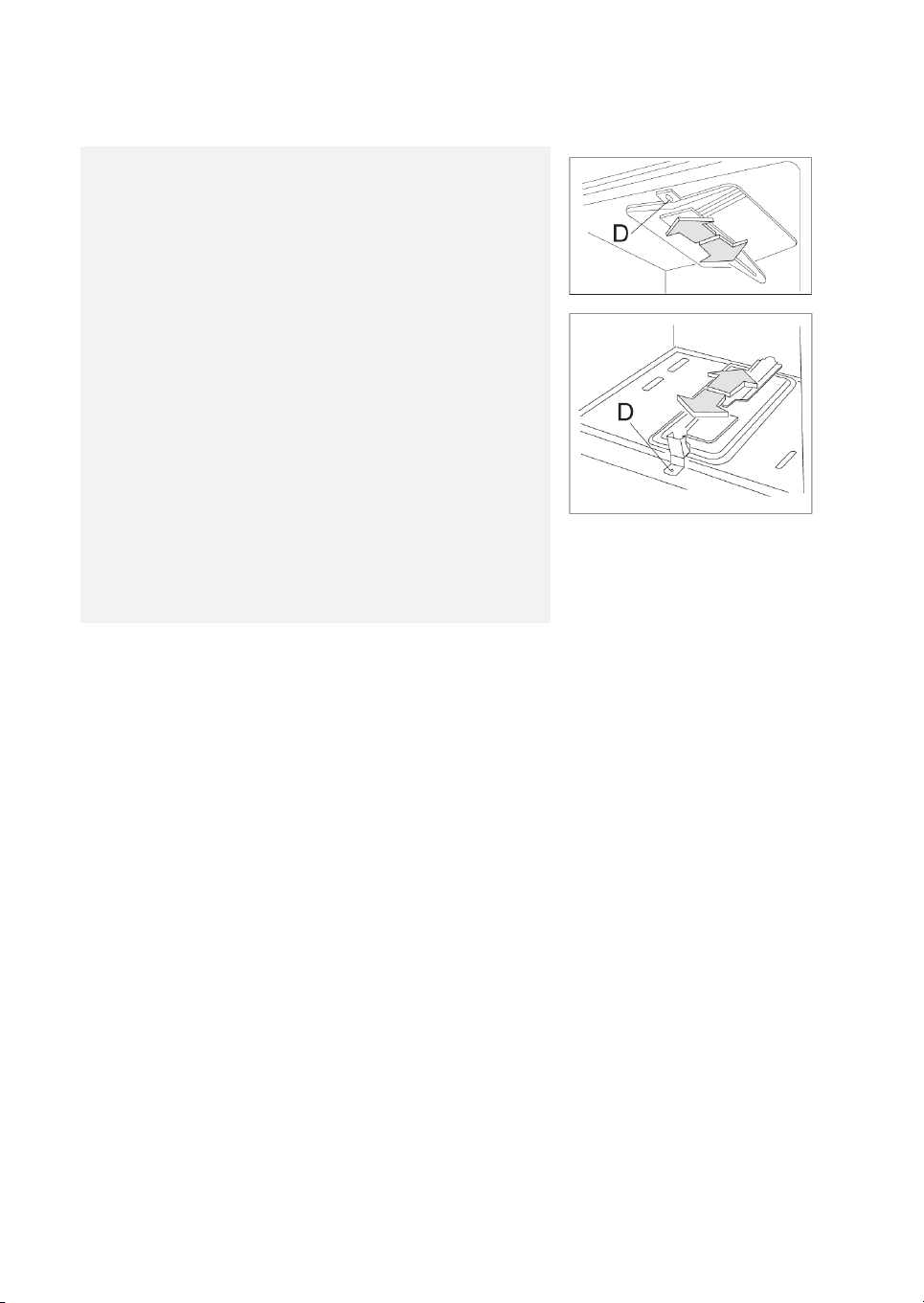
To change the oven injector, it is necessary to act as follows:
open the oven door, remove the oven accessories and the lower
side of the oven.
Unscrew the back screw D, fixing the burner to the bottom of the
oven, in order to take it away and enter the injector (Fig. 8).
Change the injector and replace it with another one suitable for
the new gas type (see table in separate Product Sheet).
Re-assemble everything in the opposite direction, paying
attention to place the burner in the right way on its rear slot.
Once the proper injector has been assembled, remount the
burner of the oven.
To change the grill injector, it is necessary to act as follows:
open the oven door, remove the oven accessories and unscrew
the screw D, fixing the burner to the top of the oven, in order to
take it away and enter the injector (Fig. 8).
Change the injector and replace it with another one suitable for
the new gas type (see table in separate Product Sheet).
Re-assemble everything in the opposite direction, paying
attention to place the burner in the right way on its rear slot.
Once the proper injector has been assembled, remount the
burner of the oven.
Fig. 8
Grill
Oven
 Loading...