


Service
This manual is to be used by qualified appliance technicians only. Maytag does not assume any responsibility for property damage or personal injury for improper service procedures done by an unqualified person.
Top Load
Washer
©2005 Maytag Services
Important Information
Important Notices for Servicers and Consumers
Maytag will not be responsible for personal injury or property damage from improper service procedures. Pride and workmanship go into every product to provide our customers with quality products. It is possible, however, that during its lifetime a product may require service. Products should be serviced only by a qualified service technician who is familiar with the safety procedures required in the repair and who is equipped with the proper tools, parts, testing instruments and the appropriate service information. IT IS THE TECHNICIANS RESPONSIBLITY TO
REVIEW ALL APPROPRIATE SERVICE INFORMATION BEFORE BEGINNING REPAIRS.
!WARNING
To avoid risk of severe personal injury or death, disconnect power before working/servicing on appliance to avoid electrical shock.
To locate an authorized servicer, please consult your telephone book or the dealer from whom you purchased this product. For further assistance, please contact:
Customer Service Support Center
CAIR Center |
|
Web Site |
Telephone Number |
WWW.MAYTAG.COM ............................................. |
1-800-688-9900 |
WWW.AMANA.COM................................................ |
1-800-843-0304 |
CAIR Center in Canada ........................................... |
1-800-688-2002 |
Amana Canada Product ........................................... |
1-866-587-2002 |
Recognize Safety Symbols, Words, and Labels
!DANGER
DANGER—Immediate hazards which WILL result in severe personal injury or death.
!WARNING
WARNING—Hazards or unsafe practices which COULD result in severe personal injury or death.
!CAUTION
CAUTION—Hazards or unsafe practices which COULD result in minor personal injury, product or property damage.
2 |
16026502 |
©2005 Maytag Services |
Important Information .................................................... |
2 |
Important Safety Information ......................................... |
4 |
General Information |
|
Model Identification .................................................... |
7 |
Serial Label Location ................................................. |
7 |
Model Nomenclature .................................................. |
8 |
Troubleshooting |
|
Troubleshooting General Symptoms .......................... |
9 |
Troubleshooting (Electronic Controls) ....................... |
10 |
Troubleshooting (Mechanical Controls) ..................... |
14 |
Component Specifications |
|
Component Testing Information (Electronic) .............. |
15 |
Component Testing Information (Mechanical) ............ |
16 |
Service Specifications ............................................... |
17 |
Disassembly Procedures |
|
Console Disassembly ............................................... |
18 |
Drain Pump/Belt Removal ......................................... |
19 |
Top Cover Removal ................................................... |
20 |
Hinge/Lid Removal .................................................... |
20 |
Lid Switch Removal .................................................. |
20 |
Water Valve Removal ................................................ |
21 |
Dispenser Removal ................................................... |
21 |
Front Panel Removal................................................. |
21 |
Motor Removal .......................................................... |
22 |
Flume/ThermistorRemoval ......................................... |
22 |
Tub Top Removal ....................................................... |
23 |
Agitator/Spinner/Outer Tub/TransmissionRemoval .... |
23 |
Tub Seal/Transmission Disassembly ........................ |
25 |
Drive Pulley and Cam Removal .................................. |
26 |
Brake Disassembly ................................................... |
26 |
Tub Seal Replacement .............................................. |
27 |
Spin Bearing Replacement ........................................ |
27 |
Oil Seal Replacement ............................................... |
27 |
Snubber/Brake Assembly ......................................... |
27 |
Installing Thrust Bearing ........................................... |
28 |
Base Replacement ................................................... |
28 |
Transmission Operation ............................................ |
29 |
Determine Brake Rotor Condition ............................. |
29 |
Brake Adjustment ..................................................... |
29 |
Check Brake Disengagement ................................... |
30 |
To Adjust Brake Disengagement ............................... |
30 |
Appendix A |
|
Installation Instructions ........................................... |
A-1 |
Appendix B |
|
Use & Care Information ........................................... |
B-1 |
©2005 Maytag Services |
16026502 |
3 |

Important Safety Information
To reduce the risk of fire, electric shock, serious injury or death to persons when using your washer, follow these basic precautions:
•Read all instructions before using the washer.
•Refer to the Grounding Instructions in the Installation Manual for the proper grounding of the washer.
•Do not wash articles that have been previously cleaned in, washed in, soaked in, or spotted with gasoline, dry-cleaning solvents, or other flammable or explosive substances as they give off vapors that could ignite or explode.
•Do not add gasoline, dry-cleaning solvents, or other flammable or explosive substances to the wash water. These substances give off vapors that could ignite or explode.
•Under certain conditions, hydrogen gas may be produced in a hot water system that has not been used for two weeks or more. Hydrogen gas is explosive. If the hot water system has not been used for such a period, before using a washing machine or combination washer-dryer, turn on all hot water faucets and let the water flow from each for several minutes. This will release any accumulated hydrogen gas. The gas is flammable, do not smoke or use an open flame during this time.
•Do not allow children to play on or in the washer. Close supervision of children is necessary when the washer is used near children. This is a safety rule for all appliances.
•Before the washer is removed from service or discarded, remove the lid to the washing compartment.
•Do not reach into the washer if the wash tub is moving.
•Do not install or store the washer where it will be exposed to water and/or weather.
•Do not tamper with the controls.
•Do not repair or replace any part of the washer, or attempt any servicing unless specifically recommended in the User-Maintenance instructions or in published user-repair instructions that you understand and have the skills to carry out.
•To reduce the risk of an electric shock or fire, do not use an extension cord or an adapter to connect the washer to the electrical power source.
•Use your washer only for its intended purpose, washing clothes.
•Always disconnect the washer from electrical supply before attempting any service. Disconnect the power cord by grasping the plug, not the cord.
•Install the washer according to the Installation Instructions. All connections for water, drain, electrical power and grounding must comply with local codes and be made by licensed personnel
when required. Do not do it yourself unless you know how!
•To reduce the risk of fire, clothes which have traces of any flammable substances such as vegetable oil, cooking oil, machine oil, flammable chemicals, thinner, etc. or anything containing wax or chemicals such as in mops and cleaning cloths, must not be put into the washer. These flammable substances may cause the fabric to catch on fire by itself.
•Do not use fabric softeners or products to eliminate static unless recommended by the manufacturer of the fabric softener or product.
•Keep your washer in good condition. Bumping or dropping the washer can damage safety features. If this occurs, have your washer checked by a qualified service person.
•Replace worn power cords and/or loose plugs.
•Be sure water connections have a shut-off valve and that fill hose connections are tight. Close the shut-off valves at the end of each wash day.
•Loading lid must be closed any time the washer is in operational fill, tumble, or spin. Do not attempt to bypass the loading lid switch by permitting the washer to operate with the loading lid open.
•Always read and follow manufacturer’s instructions on packages of laundry and cleaning aids. Heed all warnings or precautions. To reduce the risk of poisoning or chemical burns, keep them out of the reach of children at all times (preferably in a locked cabinet).
•Always follow the fabric care instructions supplied by the garment manufacturer.
•Never operate the washer with any guards and/or panels removed.
•Do not operate the washer with missing or broken parts.
•Do not bypass any safety devices.
•Failure to install, maintain, and/or operate this washer according to the manufacturer’s instructions may result in conditions which can produce bodily injury and/or property damage.
NOTE: The Warnings and Important Safety Instructions appearing in this manual are not meant to cover all possible conditions and situations that may occur. Common sense, caution and care must be exercised when installing, maintaining, or operating the washer.
Always contact your dealer, distributor, service agent or the manufacturer about any problems or conditions you do not understand.
4 |
16026502 |
©2005Maytag Services |

Important Safety Information
To avoid personal injury or death from improper servicing, make sure you read and understand the descriptions and meaning of various safety symbols, words and labels used in this manual, before attempting any procedures described in the manual. Failure to understand and comply with safety information may result in severe personal injury or death.
General Information
This Service Manual describes the operation, disassembly, troubleshooting, and repair of the washer. It is intended for use by authorized technicians who troubleshoot and repair these units.
NOTE: It is assumed that users of this manual are familiar with the use of tools and equipment used to troubleshoot and repair electrical, and mechanical systems; and understand the terminology used to describe and discuss them.
Related Publications
This is a base service manual, covering a range of similar models. It is intended to be used in conjunction with the Parts Manual and Technical Sheet covering the specific model being serviced.
Electrical Service Information
Proper Grounding and Polarization of 120 Volts Wall Outlets
For the safety of our customers and the Service Technician, ALL appliances have a three–prong power cord and MUST be connected to a properly polarized AND grounded wall outlet.
This information was written for those who do not understand grounding and polarization of a wall outlet. A 120 volt wall outlet must always be wired as shown below.
|
Ground |
L1 |
Neutral |
|
|
Neutral |
|
side |
0 |
115±12 |
|
V.A.C. |
V.A.C. |
Round |
V.A.C. |
grounding |
|
|
115±12 |
prong |
|
About Ground Wires
In the event of an electrical short circuit, a ground wire reduces the risk of electric shock by providing an escape wire for the electric current.
Standard accepted color coding for ground wires is green or green with a yellow stripe.
Grounding wires and wires colored like grounding wires are NOT to be used as current carrying conductors.
To reduce the risk of fire, electric shock, serious injury or death, all wiring and grounding must conform with the latest edition of the National Electric Code, ANSI/ NFPA 70, or the Canadian Electrical Code, CSA C22.1, and such local regulations as might apply. It is the customer’s responsibility to have the wiring and fuses checked by a qualified electrician to make sure your home has adequate electrical power to operate the washer.
To avoid risk of personal injury or death due to electrical shock:
•Observe all local codes and ordinances.
•Disconnect electrical power to unit before servicing.
•Ground appliance properly.
•Check with a qualified electrician if you are not sure this appliance is properly grounded.
•DO NOT ground to gas line.
•DO NOT ground to cold water pipe if pipe is interrupted by plastic, nonmetallic gaskets, or other insulating (nonconducting) materials.
•DO NOT modify plug on power cord. If plug does not fit electrical outlet, have proper outlet installed
by qualified electrician.
•DO NOT have a fuse in the neutral or ground circuit. A fuse in the neutral or ground circuit could result in an electrical shock.
•DO NOT use an extension cord with this appliance.
•DO NOT use an adapter plug with this appliance.
•DO NOT pinch power cord.
©2005Maytag Services |
16026502 |
5 |

Important Safety Information
Explanation
Polarization–This means that the larger slot must be neutral and the small slot must be at line voltage. Mispolarized–The outlet is incorrectly wired so that the larger slot is at line voltage and the smaller slot is neutral. Grounded–This means the round hole connection is connected to earth ground through a connection to the main power panel.
Ungrounded–The round hole connection is not complete to earth ground and/or the main power panel.
Grounding Instructions
•To avoid the risk of electrical shock or death, do not alter the plug.
•Do not remove grounding prong when installing grounded appliance in a home that does not have three wire grounding receptacle. Under no condition is grounding prong to be cut off or removed. It is the personal responsibility of the consumer to contact a qualified electrician and have properly grounded three prong wall receptacle installed in accordance with appropriate electrical codes.
•To avoid the risk of electrical shock or death, this equipment must be grounded.
This equipment MUST be grounded. In the event of an electrical short circuit, grounding reduces the risk of electric shock by providing an escape wire for the electric current. This unit is equipped with a cord having a grounding wire with a grounding plug. The plug must be plugged into an outlet that is properly installed and grounded.
Consult a qualified electrician or technician if grounding instructions are not completely understood, or if doubt exists as to whether the equipment is properly grounded. Do not use an extension cord. If the product power cord is too short, have a qualified electrician install a three-slot receptacle. This unit should be plugged into a separate 60 hertz circuit with the electrical rating as shown in the appropriate drawing. Models operate with a supply voltage of 120 Volts.
6 |
16026502 |
©2005Maytag Services |

General Information
Model Identification
Complete registration card and promptly return. If registration card is missing:
•For Maytag product call 1-800-688-9900 or visit the Web Site at www.maytag.com
•For product in Canada call 1-866-587-2002 or visit the Web Site at www.maytag.com.
When contacting provide product information located on rating label. Record the following:
Model Number: |
___________________ |
Manufacturing Number: |
___________________ |
Serial or S/N Number: |
___________________ |
Date of purchase: |
___________________ |
Dealer’s name and address: |
___________________ |
Serial Label is located on the back of the unit and on top of the Console.
Service
Keep a copy of sales receipt for future reference or in case warranty service is required. To locate an authorized technician:
•For Maytag call 1-800-462-9824 or visit the Web Site at www.maytag.com.
•For product in Canada call 1-866-587-2002 or visit the Web Site at www.maytag.com.
Warranty service must be performed by an authorized technician. We also recommend contacting an authorized technician, if service is required after warranty expires.
Parts and Accessories
Purchase replacement parts and accessories over the phone. To order accessories for your product call:
•For Maytag product call 1-800-462-9824 or visit the Web Site at www.maytag.com.
•For product in Canada call 1-866-587-2002 or visit the Web Site at www.maytag.com.
Extended Service Plan
We offer long-term service protection for this new washer.
•Dependability PlusTM Extended Service Plan is specially designed to supplement Maytag’s strong warranty. This plan covers parts, labor, and travel charges.
Call 1-800-925-2020 for information.
©2005Maytag Services |
16026502 |
7 |

General Information
Washer Nomenclature
A = Admiral |
M = Maytag |
P = Performa |
C = Crosley |
N = Amana |
H = Hoover |
AV = Automatic Vertical |
|
This identifies which |
XXXX = Feature Package |
version of production the |
|
unit is. |
|
|
|
|
|
|
|
|
|
|
|
|
|
|
|
|
|
|
|
|
|
|
|
|
|
|
|
|
|
|
|
|
|
|
|
|
|
|
|
|
|
|
|
|
|
|
|
|
W |
White |
||||
|
|
|
Q |
Bisque |
||||
|
|
|
K |
Metallic Blue |
||||
|
|
|
|
|
|
|
|
|
|
|
|
|
|
|
|
|
|
A Australia 220-240V-50 Hz
G Generic Europe 220-240V-60 Hz
J


K220V-60 Hz (2 wire)
R220V-50 Hz
T208/240V-60 Hz
W120V-60 Hz (for US)
Y240V-60 Hz (for US)
ZCanada 240V-60hz
Troubleshooting and Diagnostic Guide is located inside the Console.
8 |
16026502 |
©2005Maytag Services |
Troubleshooting Procedures
Due to possibility of personal injury or property damage, always contact an authorized technician for servicing or repair of this unit.
 !
! CAUTION
All safety information must be followed as provided in the Service Manual.
!WARNING
To avoid risk of electrical shock, personal injury or death, disconnect power to unit before servicing.
Noisy and/or Vibration/Walking
•Check for proper installation and leveling of unit.
•Legs properly adjusted and locked with no damage.
•Stabilizer rear legs secure and locking properly (not jamming).
•Pads on feet of leveling legs.
•Solid and secure flooring.
•Check condition of belt.
•Check transmission pulley for correct Thrust Bearing adjustment.
•Check transmission for spin bearing noise.
•Check center tub seal.
•Check agitator for correct installation.
•Check the suspension springs are properly installed and lubricated.
•Check for loose screws on the cabinet.
•Check base is flat against floor.
Over Fill
•Check water pressure to washer is 20 PSI minimum.
•Disconnect power cord. Replace Water Valve if it continues to flow.
•Check Pressure Switch for proper operation.
•Check Pressure Switch air hose for leaks damage or obstruction.
Finger Faucet
•Faucet will not operate with washer set to Hot/Cold.
Wrong Water Temperature
•Run the Service Cycle to verify water temperatures.
•Check that both faucets are turned on fully.
•Make sure water heater is set to deliver a minimum of 120°F (49°C) hot water at the tap. Also check water heater capacity and recovery rate.
•If the water heater is located a long distance from washer, the water line may need to be purged prior to starting wash cycle.
•Check for reversed inlet hoses at the faucet or water valve.
•Check wiring at the Water Valve, Timer, and ATC.
Will Not Spin/Spin Speed Too Slow
•Check power supply to washer is between 108V to 132V with a load on the circuit.
•Check slow spin speed is not selected.
•Refer to Service Cycle and check spin speeds.
•Check condition of drive belt.
•Check drain system in the home is functioning properly.
•Check for blocked or kinked drain hose.
•Check for binding Tub Seal.
•Check brake is disengaging properly.
•Check between tubs for something contacting spinner.
•Check for proper adjustment of the Thrust Bearing.
•Check for broken impeller on Drain Pump.
•Perform Torque Test.
•When washer passes all checks place a one pound unbalance weight in washer and check for 600 RPM. If washer fails check brake and cam adjustments. Replace Transmission if brake and cam adjustments are ok.
Will Not Run or Start
•Plug cord into live electrical outlet. Check for proper voltage.
•Check fuse or reset circuit breaker.
•Check water supply is working.
•Check water valve connections are good.
•Check the line filter and water valve filter.
•Check if Lid Switch is functional. Lid must be closed before washer will operate.
•Check Control Board is operating properly.
•Check drive motor is operating properly.
•Check for a blown thermal fuse.
•Check for obstructions in Drain Pump.
•Turn transmission pulley by hand. If locked in agitation direction, replace transmission.
•Power supply to washer is between 108V and 132V during a load on circuit.
No Water Fill
•Check to make sure water supply is turned on fully.
•Check electrical circuit and connections at the Water Valve, and Pressure Switch.
•Check for kinks in inlet hoses.
•Check for clogged inlet screens.
•Check Water Valves separately for fill.
•Check for low water pressure. May be dependent on pressure entering home. Variations may occur due to usage in the home at the time machine is used.
•Check for frozen pipes and hoses.
•Check resistance of Water Valve coils.
•Check for loose connections at the Pressure Switch or on the Machine Control Board
Will Not Drain
•Check for restricted drain system.
•In cold climates check for frozen drain hose.
•Check tub to pump hose for twist in hose.
©2005 Maytag Services |
16026502 |
9 |
Troubleshooting Procedures
Due to possibility of personal injury or property damage, always contact an authorized technician for servicing or repair of this unit.
 !
! CAUTION
All safety information must be followed as provided in the Service Manual.
!WARNING
To avoid risk of electrical shock, personal injury or death, disconnect power to unit before servicing.
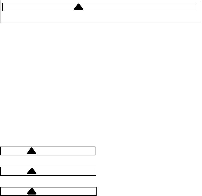
ENTER SERVICE MODE
Rotate the Cycle Selector Knob to the “Power Off” position and press knob.
(All LED’s will be off).
Rotate the Cycle Selector Knob clockwise past “Power Off” twice and stop at “Regular”.
(LED’s will illuminate as the knob is rotated).
Rotate the Cycle Selector Knob counterclockwise one revolution back to “Regular” and press knob.
• Power Off, Rinse & Spin LED will blink (if error codes are present). Regular LED will be illuminated.
• Model I.D. is displayed by the LED’s around the bottom of the dial.
• Model I.D. can be redisplayed while in Service Mode by setting knob to “Handwash” and pressing.
• Refer to chart for Model I.D.
10 |
16026502 |
©2005 Maytag Services |
Troubleshooting Procedures
Due to possibility of personal injury or property damage, always contact an authorized technician for servicing or repair of this unit.
 !
! CAUTION
All safety information must be followed as provided in the Service Manual.
!WARNING
To avoid risk of electrical shock, personal injury or death, disconnect power to unit before servicing.
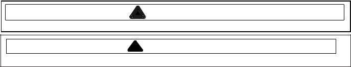
EXIT SERVICE MODE
Rotate Cycle Selection Knob to “Power Off” and press knob.
or
Allow 5 minutes of inactivity. or
Disconnect power
DISPLAY/CLEAR SERVICE CODES
Enter Service Mode then set Cycle Selection Knob to “Rinse & Spin”. Press knob
• Rinse & Spin LED will blink if codes other than power interrupt are present.
• Press knob to view codes. Press once for each code. Codes are displayed newest to oldest. Machine beeps three times after last service code is displayed.
• To clear codes display a code then press and hold Cycle Selection Knob until machine beeps twice. Rinse & Spin LED stops blinking.
• Refer to chart for Service Codes.
CONSOLE SWITCH TEST
Enter Service Mode then set Cycle Selection Knob to “Delicate” and press knob.
• Power Off LED blinks.
•Pause and Delicates LED’s are
illuminated.
Rotate the Cycle Selection Knob clockwise for ascending, and counterclockwise for decending test mode. Rotate 32 clicks in the same direction to complete the test.
|
|
|
11 |
©2005 Maytag Services |
16026502 |
||
Troubleshooting Procedures
Due to possibility of personal injury or property damage, always contact an authorized technician for servicing or repair of this unit.
 !
! CAUTION
All safety information must be followed as provided in the Service Manual.
!WARNING
To avoid risk of electrical shock, personal injury or death, disconnect power to unit before servicing.
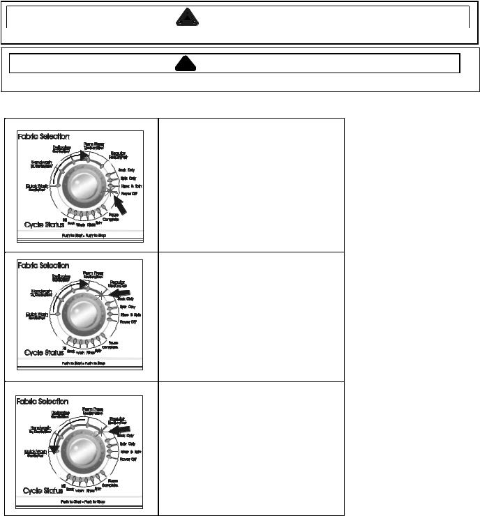
CONSOLE SWITCH TEST CON’T
|
Press the Cycle Selection Knob to activate |
|
|
the test for the rotary switches. The test |
|
|
begins with the rotary switch imediately to |
|
|
the left of the Cycle Selection Knob. |
|
|
Rotate the switch in either direction. The |
|
|
LED’s illuminate around the bottom of the |
|
|
Cycle Selection Knob for each switch |
|
|
|
position. |
|
NOTE: Any attempt to move a knob or |
|
|
|
switch other than the one being |
|
|
tested results in a chirp sound. |
|
Press the Cycle Selection Knob. The test |
|
|
continues with the switch immediately to |
|
|
the left of the previous switch tested. |
|
|
Repeat rotating the switch and monitoring |
|
|
the LED’s around the bottom of the Cycle |
|
X |
Selection Knob. Continue pressing the |
|
Cycle Selection Knob for each switch |
||
tested right to left untill all rotary switches |
||
|
are tested. |
|
NOTE: |
The Water Level Switch is not |
|
included in this test. |
||
|
• After the last rotary switch is tested the |
|
|
next time the Cycle Selection Knob is |
|
|
pressed the test will continue with the |
|
|
rocker switches. Continue pressing |
|
|
the Cycle Selection Knob and testing |
|
|
switches until the last switch is tested. |
|
|
When all switches have been tested |
|
|
the “Complete” LED will illuminate. |
|
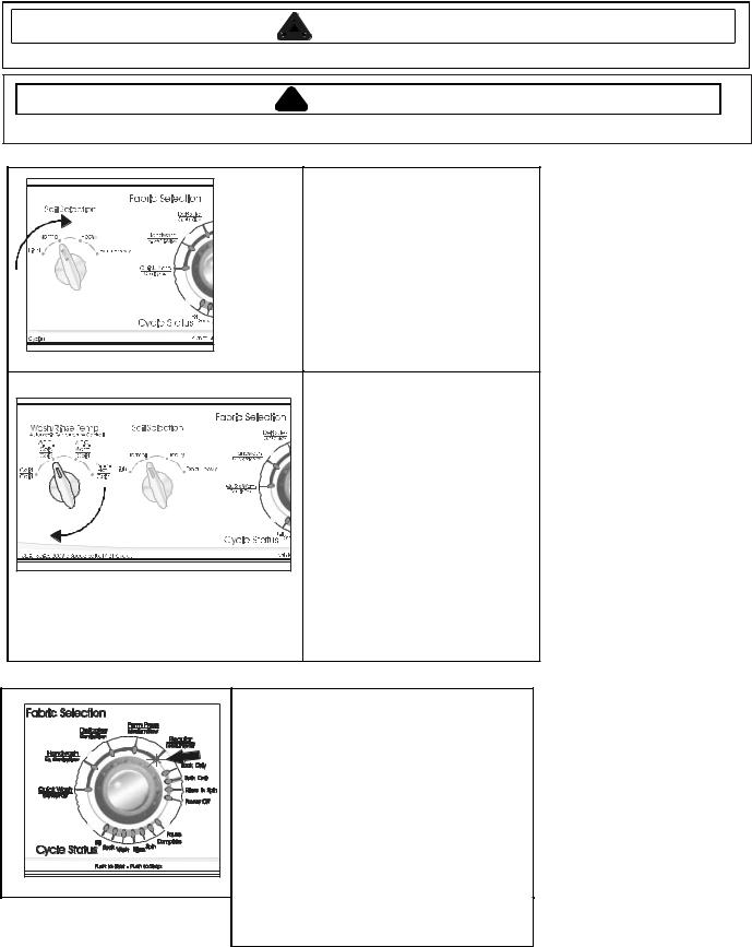
SERVICE CYCLE |
|
|
|
Enter Service Mode then set Cycle Selection Knob to |
|
|
“Regular” and press knob. |
|
|
• Fill and Wash LED’s illuminate. Hot water fill. |
|
|
• Press knob Fill and Rinse LED’s illuminate. Cold |
|
|
water fill. |
|
|
• Press knob Fill, Wash, and Rinse LED’s illuminate. |
|
|
Selected wash temperature fill. |
|
|
• Press knob Wash LED illuminates. Slow agitation. |
|
|
• Press knob Wash LED blinking. Fast agitation. |
|
|
• Press knob Spin LED illuminates. Slow spin. |
|
|
• Press knob Spin LED blinking. Fast spin. |
|
|
• Press Knob Complete LED illuminates. |
|
|
• Press knob exit back to Service Mode. |
|
|
NOTE: Fills are skipped if Pressure Switch is satisfied. |
|
|
Press knob until Pause LED begins blinking |
|
|
to pause cycle. |
|
12 |
16026502 |
©2005 Maytag Services |
Troubleshooting Procedures
Due to possibility of personal injury or property damage, always contact an authorized technician for servicing or repair of this unit.
 !
! CAUTION
All safety information must be followed as provided in the Service Manual.
!WARNING
To avoid risk of electrical shock, personal injury or death, disconnect power to unit before servicing.
Codes displayed but not listed here should be ignored.
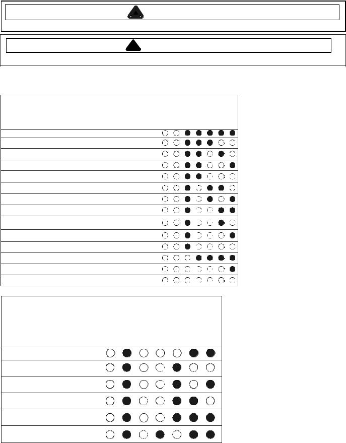
DIAGNOSTIC CODE CHART
|
Service |
|
Service Code Description |
Code |
|
Model ID Unknown, Default model of 31 used |
31 |
|
Rotary Switch 3 left of encoder failed at startup |
28 |
|
Rotary Switch 2 left of encoder failed at startup |
26 |
|
Rotary Switch 1 left of encoder failed at startup |
25 |
|
Incorrect rotary switch position seen |
24 |
|
Fill time less than 2 seconds |
22 |
|
Fill time exceeded 18 minutes |
21 |
|
Motor Thermal protector opened |
19 |
|
Motor Thermal protector opened more than |
18 |
|
5 times during a cycle |
||
|
||
Thermistor Possible Short |
17 |
|
Thermistor Possible Open |
16 |
|
Thermistor out of range |
15 |
|
Power Failure detected |
1 |
|
No code |
0 |
Fill |
Soak |
Wash |
Rinse |
Spin |
Complete |
Pause |
MODEL CODE CHART
Model Numbers |
Fill Soak |
Wash Rinse |
MAV546E |
|
|
MAV5920 AGW (INT) |
|
|
MAV508DE, MAV551E
MAV5758, MAV5858
MAV5920E
NAV8805
Pause
Complete
Spin
©2005 Maytag Services |
16026502 |
13 |
Troubleshooting Procedures
Due to possibility of personal injury or property damage, always contact an authorized technician for servicing or repair of this unit.
 !
! CAUTION
All safety information must be followed as provided in the Service Manual.
!WARNING
To avoid risk of electrical shock, personal injury or death, disconnect power to unit before servicing.
Mechanical Control Version.
Noisy and/or Vibration/Walking
•Check for proper installation and leveling of unit.
•Legs properly adjusted and locked with no damage.
•Stabilizer rear legs secure and locking properly (not jamming).
•Solid and secure flooring.
•Check condition of belt.
•Check transmission for spin bearing noise.
•Check center tub seal.
•Check agitator for correct installation.
•Check the suspension springs are properly installed and lubricated.
•Check for loose screws on the cabinet.
•Check for damaged base.
Over Fill
•Check water pressure to washer should be a 20 PSI minimum.
•If water drips into machine while off, replace valve.
•Disconnect power cord. Replace Water Valve if it continues to flow.
•Check Pressure Switch for proper operation.
•Check Pressure Switch air hose for leaks damage or obstruction.
Wrong Water Temperature
•Check that both faucets are turned on fully.
•Make sure water heater is set to deliver a minimum of 120°F (49°C) hot water at the tap. Also check water heater capacity and recovery rate.
•Check for reversed inlet hoses at the faucet or water valve.
•With tub empty, select normal wash no ATC and Cold/Cold temperature setting. Let washer fill and check fill time and full tub temperature.
•Select normal wash no ATC and hot water temperature setting. Let washer fill and check fill time and full tub temperature. For extended wait time for hot water fill, instruct to purge water line for a hot wash.
•Select normal wash no ATC and Warm/Cold water temperature setting. Let washer fill and check fill time and full tub temperature.
•Check wiring at the Water Valve, Timer, and ATC.
Will Not Spin/Spin Speed Too Slow
•Check power supply to washer is between 108V to 132V with a load on the circuit.
•Check for out of balance clothes load.
•Check slow spin speed is not selected.
•Check condition of drive belt.
•Check drain system in the home is functioning properly.
•Check for blocked or kinked drain hose.
•Check for binding Tub Seal.
•Check brake is disengaging properly.
•Check motor slide and spring for proper movement.
•Check between tubs for something contacting spinner.
•Check for proper adjustment of the Thrust Bearing.
•Check for broken impeller on Drain Pump, washer should drain all water within 90 seconds.
•When washer passes all checks place a one pound unbalance weight in washer and check for 600 RPM. If washer fails, check brake and cam adjustments. Replace Transmission if brake and cam adjustments are ok.
Motor Not Running
•Check power supply to washer is between 108V and 132V during a load on circuit.
•Check if Lid Switch is functional. Lid must be closed before washer will operate.
•Check voltage going into, and out of timer to start and run windings, per ladder diagram.
•Check for 120 volts to start and run winding at motor per ladder diagram.
•Check for a blown motor thermal fuse.
•Check for obstructions in Drain Pump.
•Turn transmission pulley by hand. If locked in agitation direction, replace transmission.
No Water Fill
•Check to make sure water supply is turned on fully.
•Check electrical circuit and connections at the Water Valve, and Pressure Switch.
•Check for kinks in inlet hoses.
•Check for clogged inlet screens and water valve screens.
•Check Water Valves separately for fill.
•Check for low water pressure. May be dependent on pressure entering home. Variations may occur due to usage in the home at the time machine is used.
•Check for frozen pipes and hoses.
•Check hot and cold water valve voltage for 120 volts.
•If washer fills and drains at the same time, check for drain hose siphoning.
Will Not Drain
•Check for restricted drain system.
•In cold climates check for frozen drain hose.
•Check for broken impeller on Drain Pump. Washer should drain all water within 90 seconds.
•Check motor slide and spring for proper movement.
14 |
16026502 |
©2005 Maytag Services |
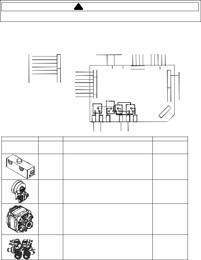
Component Testing Information
!WARNING
To avoid the risk of electrical shock, personal injury, or death, disconnect power to unit before servicing, unless testing requires power.
Electronic Controls
Resistance and voltage checks of components listed below can be made at PS5 on the control board.
Note: When making resistance checks on the components listed below, washer must be unplugged and PS5 connector disconnected from control board.
WA HS RE
D MO SE CTI
|
GY |
1 |
|
|
1 |
|
|||
GY |
|
|
|
|
11 |
3 |
|
||
BK |
|
|
|
|
13 |
|
7 |
|
|
WH |
|
|
|
|
15 |
|
9 |
|
|
OR |
|
11 |
|
|
3 |
|
|
||
5 |
YL |
|
3 |
|
PU |
1 |
|
||
7 |
|
5 |
|
|
PK |
|
1 |
|
|
9 |
|
7 |
|
|
|
|
1 |
|
|
VIEW “A”
PS5
(EXPORT ONLY)
AW HS RE
XE OP TR
GY OR
YL PU
PK GY BK WH
|
|
|
|
|
|
|
|
|
|
|
|
|
|
|
|
|
|
|
RUBPUBKB |
LY LY/ DRKB H/ UWH L//D W B Y R |
|
|
|
|
||||||||||||||
|
|
|
|
|
|
|
|
|
|
|
|
|
|
|
|
|
|
|
|
|
|
|
||||||||||||||||
|
|
|
|
|
|
|
|
|
|
|
|
|
|
|
|
|
|
|
4 |
|
3 |
|
2 |
|
1 |
|
|
|
|
|
|
|
|
|
||||
|
|
8 |
7 |
6 |
5 |
|
4 3 |
2 |
1 |
|
|
|
|
|
|
|
5 |
4 |
3 2 |
1 |
|
|
|
|
||||||||||||||
|
|
|
|
|
|
|
|
|
|
|
|
|
|
|
|
|
|
|
|
|
|
|
|
|
|
|
|
|
|
|
|
|
|
|
|
|
||
1 |
|
|
|
|
|
|
|
|
PS1 |
|
|
|
|
|
|
|
PS6 |
|
|
PS4 |
|
|
9 |
|
|
|
||||||||||||
|
|
|
|
|
|
|
|
|
|
|
|
|
|
|
|
|
|
|
|
|||||||||||||||||||
3 |
|
|
|
|
|
|
|
|
|
|
|
|
|
|
|
|
|
|
|
8 |
|
|||||||||||||||||
|
|
|
|
|
|
|
|
|
|
|
|
|
|
|
|
|
|
|
|
|
|
|
|
|
|
|
|
|
|
|
|
|
||||||
5 |
|
|
|
|
|
|
|
|
|
|
|
|
|
|
|
|
|
|
|
|
|
|
|
|
|
|
|
|
|
|
|
|
|
|
|
|
||
|
|
|
|
|
|
|
|
|
|
|
|
|
|
|
|
|
|
|
|
|
|
|
|
|
|
|
|
|
|
|
7 |
|
|
|||||
|
9 S5P |
|
|
|
|
|
|
|
|
|
|
|
|
|
|
|
|
|
|
|
|
|
|
|
|
|
|
|
|
|||||||||
|
|
|
|
|
|
|
|
|
|
|
|
|
|
|
|
|
|
|
|
|
|
|
|
|
|
|
|
56 |
||||||||||
7 |
|
|
|
|
|
|
|
CONTROL BOARD |
|
|
|
|
|
|
|
|||||||||||||||||||||||
3 |
|
|
|
|
|
|
|
|
|
|
|
|
|
|
||||||||||||||||||||||||
1 |
|
|
|
|
|
|
|
|
|
|
|
|
|
|
|
|
|
|
|
|
|
|
|
|
|
|
|
|
|
|
43 PS2 |
|
|
|||||
1 |
|
|
|
|
|
|
|
|
|
|
|
|
|
|
|
|
|
|
|
|
|
|
|
|
|
|
|
|
|
|
|
|||||||
1 |
|
|
|
|
|
|
|
|
|
|
|
|
|
|
|
|
|
|
|
|
|
|
|
|
|
|
|
|
|
|
|
|
|
|
|
|
||
|
15 |
|
|
|
|
|
|
|
|
|
|
|
|
|
|
|
|
|
|
|
|
|
|
|
|
|
|
|
|
|
|
|
|
|
|
|
|
|
|
|
|
|
|
|
|
START |
|
|
|
|
|
|
|
|
|
|
|
|
|
|
|
|
|
|
|
|
|
|
2 |
|
|
||||||
|
|
|
|
|
|
|
|
|
|
|
|
|
|
|
|
|
|
|
|
|
|
|
|
|
|
|
|
|
|
|||||||||
|
HI/LO |
|
|
DIRECTION |
|
|
|
|
|
|
|
1 |
|
|
||||||||||||||||||||||||
|
|
|
|
|
|
|
|
|
|
|
||||||||||||||||||||||||||||
|
SPEED |
|
RE2 |
|
|
|
|
|
|
|
|
|
|
|
|
|||||||||||||||||||||||
|
|
|
|
|
|
|
|
|
|
|
|
|
|
|
|
|
|
|
|
|
|
|
|
|
|
|
|
|||||||||||
|
|
RE3 |
|
RE1 |
RE0 |
|
|
|
|
|
|
|
|
|
|
|
||||||||||||||||||||||
|
|
|
|
|
|
|
|
|
|
|
|
3 |
|
|
|
|
|
|||||||||||||||||||||
|
|
|
|
|
|
|
|
|
|
|
|
|
|
|
|
|
|
|
|
|
|
|
|
|
|
|
|
|
|
|
|
|
|
|
|
|
|
|
|
|
|
|
|
|
|
|
|
|
|
|
|
|
|
|
|
|
|
|
|
|
|
|
|
|
|
|
|
|
|
|
S |
|
|
|
|
||
P |
|
P |
|
PS12 |
|
S9P |
S11P |
|
PS10 |
|
|
|
|
P |
|
|
|
|
|
|
||||||||||||||||||
|
|
|
|
|
|
|
|
|
|
|
|
|
|
|
||||||||||||||||||||||||
7 |
|
8 |
|
|
|
|
|
|
|
|
|
|
|
|
|
|
|
|
|
|
|
|
|
|
|
|
|
|
|
|
|
|
|
|||||
S |
|
S |
|
|
|
|
|
|
|
|
|
|
|
|
|
|
|
|
|
|
|
|
|
|
|
|
|
|
|
|
|
|
|
|||||
|
|
|
|
|
|
|
|
|
|
|
|
|
|
|
|
|
|
|
|
|
||||||||||||||||||
GY |
OR |
WH |
|
UB |
RB |
|
DR |
|
|
|
|
|
|
|
|
|
|
|
|
|||||||||||||||||||
|
|
|
|
|
|
|
|
|
|
|
|
|
|
|
|
|
|
|
|
|
|
|
|
|
|
|
|
|
|
|
|
|
|
|
|
|
|
|
Illustration |
Component |
Test Procedure |
Results |
|
AC Power |
With the unit plugged in, check source voltage at Pin #15 |
|
|
|
|
|
|
|
WH and Pin #13 BK of PS5 on the control board............... |
120 V AC |
|
Lid Switch |
|
|
|
|
With the unit plugged in, |
120 V AC |
|
|
check voltage at Pin #5 YL and Pin #15 WH of PS5.......... |
|
|
Pressure |
|
|
|
Switch |
|
|
|
|
With unit plugged in and the tub empty, |
|
|
|
check voltage at Pin #3 OR and Pin #15 WH of PS5......... |
120 V AC |
|
Motor |
Unplug washer, disconnect harness at PS5 and test from |
|
|
|
|
|
|
|
wire insertion side of harness. |
|
|
|
Run winding - PS7 GY and Pin #5 YL of PS5..................... |
1.5 ohms |
|
|
Start winding - PS9 BU and PS10 RD................................ |
4.0 ohms without |
|
|
|
capacitor |
|
Water Valves |
Unplug washer, disconnect harness and test resistance |
|
|
|
|
|
|
|
from wire insertion side of harness. |
|
|
|
(Hot valve) Pin #9 PK of PS5 and Pin #3 OR of PS5.......... |
1120 ohms |
|
|
(Cold valve) Pin #7 PU of PS5 and Pin #3 OR of PS5........ |
1120 ohms |
|
|
(Thermistor) Pin #1 GY and Pin #11 GY of PS5................. |
53000 ohms @ 70F |
©2005 Maytag Services |
16026502 |
15 |

Component Testing Information
!WARNING
To avoid the risk of electrical shock, personal injury, or death, disconnect power to unit before servicing, unless testing requires power.
Mechanical Controls
Illustration |
Component |
Test Procedure |
Results |
|
1 Speed Motor |
Refer to Technical Data Sheet section “Internal Motor |
|
|
|
Diagram” and “Schematic” for wiring contacts. |
|
CCW rotation when viewed from shaft end.
1/2HP |
|
|
120V/60hz |
|
|
|
|
|
Water valve |
Measure resistance of terminals on each valve. |
|
120V 50/60hz, 5 |
Resistance across each valve................................................. |
1000 Ω ± 10% |
|
|
|
watts Cold Side 2.25 |
|
|
gpm, Hot Side 2.00 |
|
|
gpm, Mix 3.00 gpm at |
|
|
20-120 psi |
|
|
|
|
|
Drain Pump |
Verify Drain Pump is not clogged or damaged. |
|
Lid Switch |
Disconnect wire terminals from switch. |
|
|
|
Test terminals with switch closed.............................................. |
Continuity |
>1Ω |
|
Test terminals with switch open. .............................................. |
Infinite |
1MΩ |
Timer |
Verify input and output voltage is present. |
Refer to timing |
|
|
sequence chart on |
|
|
appropriate |
|
|
Technical Data |
|
|
Sheet. |
Pressure Switch |
Do not disconnect the pressure hose from pressure switch to |
Refer to Technical |
|
|
perform measurements. Measure resistance across the |
Data Sheet for |
|
|
following terminals. |
wiring diagram & |
|
|
|
schematic for |
|
|
|
correct contacts. |
|
|
Terminal 1 to 2................................................ ......................... |
Continuity |
>1Ω |
|
Terminal 1 to 3.......................................................................... |
Infinite |
1MΩ |
16 |
16026502 |
©2005 Maytag Services |

Service Specifications
ATC (Automatic Temperature Control) Models
Model |
Control Type |
Description |
Temperatures |
|
MAVT346AWW |
|
|
|
|
MAV3757AWW |
|
Energy Star temps, but not Energy Star rated. |
Cold 58°±8° F |
|
MAV3758AWW |
Mechanical |
Electro-mechanical washer with Automatic Temperature |
Warm 85°±8° F |
|
MAV308DAWW |
|
Control shall have full tub water temperatures as follows: |
Hot 115°±8° F |
|
|
|
|
||
MAV3905AWW |
|
|
|
|
|
|
Energy Star rated. |
Cold 58°±8° F |
|
|
|
Electro-mechanical washer with Automatic Temperature |
||
MAV3955EWW |
Mechanical |
Warm 85°±8° F |
||
Control shall have full tub water temperatures as follows: |
||||
AAV8005EWW |
|
Hot 115°±8° F |
||
|
(There shall be no warm rinse on Energy Star models) |
|||
|
|
|||
|
|
|
|
|
MAVT446AWW |
|
|
Cold 75°±8° F |
|
MAV4757AWW |
|
Standard Electro-mechanical washer with Automatic |
Warm 95°±8° F |
|
MAV4758AWW |
Mechanical |
Temperature Control shall have full tub water temperatures as |
OR |
|
MAV4755AWW |
follows: |
|||
|
|
|||
|
(Where applicable, warm rinse is not controlled.) |
|
||
MAV408DAWW |
|
Cold 58°±5° F |
||
|
|
|||
CW9505W |
|
|
Warm 85°±5° F |
|
|
|
|
||
MAVT546EWW |
|
Energy Star rated. |
|
|
MAV5758EWW |
|
Cold 58°±5° F |
||
|
Electronic washer with Automatic Temperature Control shall |
|||
MAV5920EWW |
Electronic |
Warm 85°±5° F |
||
have full tub water temperatures as follows: |
||||
MAV551EEWW |
|
Hot 115°±5° F |
||
|
(There shall be no warm rinse on Energy Star models) |
|||
|
|
|||
NAV8805EWW |
|
|
|
|
|
|
|
|
|
|
|
Electronic washer with Automatic Temperature Control shall |
Cold 70°±5° F |
|
MAV5920AGW |
Electronic |
have full tub wash water temperatures as follows: |
Warm 90°±5° F |
|
|
|
(Warm Rinse temperature shall be 80°±5° F) |
Hot 125°±5° F |
|
|
|
|
|
Fabric Selection |
Soil Level - Approximate Agitation Times, in minutes |
|
|||||||
|
|
|
|
|
Light |
Normal |
Heavy |
Extra Heavy |
|
|
Quick Wash |
|
|
2 |
|
4 |
6 |
8 |
|
|
Gentle/Fast |
|
|
|
|||||
|
|
|
|
|
|
Intermittent |
|
||
|
Hand Wash |
|
|
Intermittent |
Intermittent |
Intermittent |
|||
|
Ex. Gentle/Slow |
|
|
6 |
|
9 |
12 |
15 |
|
|
Delicates |
|
|
6 |
|
9 |
12 |
15 |
|
|
Gentle/Slow |
|
|
|
|||||
|
|
|
|
|
|
|
|
||
|
Permanent Press |
|
|
9 |
|
12 |
15 |
21 |
|
|
Medium/Slow |
|
|
|
|||||
|
|
|
|
|
|
|
|
||
|
Regular |
|
|
9 |
|
15 |
18 |
24 |
|
|
Medium/Fast |
|
|
|
|||||
|
|
|
|
|
|
|
|
||
|
Whites & Towels |
|
|
9 |
|
15 |
18 |
24 |
|
|
Normal/Fast |
|
|
|
|||||
|
|
|
|
|
|
|
|
||
Agitation Speeds |
|
|
|
|
|
|
|||
|
Gentle |
|
58 opm (oscillations per minute) |
|
|
|
|||
|
|
|
|
|
|
|
|
|
|
|
Ex. Gentle |
|
Intermittent 58 opm |
|
|
|
|
|
|
|
|
|
|
|
|
||||
|
Medium |
|
Cycles between 3 minutes at 88 opm and 3 minutes at 58 opm |
|
|
||||
|
|
|
|
|
|
|
|
|
|
|
Normal |
|
88 opm |
|
|
|
|
|
|
|
|
|
|
|
|
|
|
|
|
Spin Speeds |
|
|
|
|
|
|
|
||
|
Fast Spin |
620 +/- 25 rpm (revolutions per minute) |
|
|
|
|
|||
|
Slow Spin |
413 +/-17 rpm |
|
|
|
|
|
|
|
|
|
|
|
|
|
|
|
|
|
©2005 Maytag Services |
|
16026502 |
|
|
|
17 |
|||
Disassembly Procedures
!WARNING
To avoid risk of electrical shock, personal injury or death, disconnect power to unit before servicing.
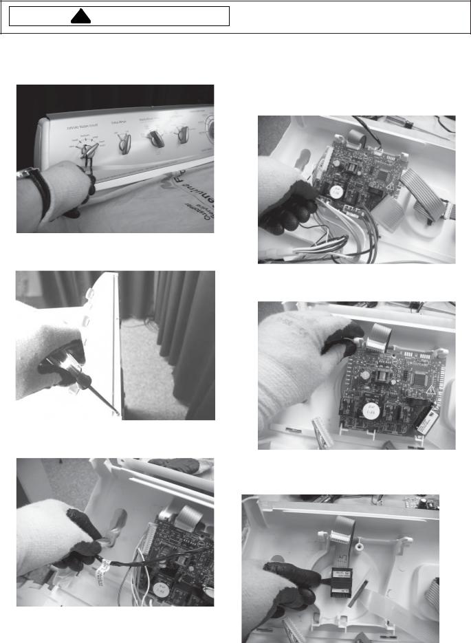
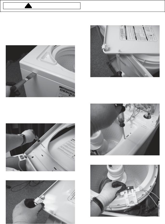
Console Disassembly
1.Disconnect power supply to unit.
2.Remove Cycle Selector Knob and Switch Knobs.
5.Disconnect all wiring harness connectors from the Circuit Board.
NOTE: Wear an Anti Static Wrist Strap and ground yourself before working with Electronic Control Boards. Always handle boards by the edge and don’t touch discreet components.
3.Remove three screws along the top of the Console and roll the Console forward.
6. Depress the PCB locking tab and remove Circuit Board.
4.Disconnect and remove Rocker Switches from Console.
7. Remove Switches by lifting locking tab and rotating Switch to align with hole molded in Console.
18 |
16026502 |
©2005 Maytag Services |

Disassembly Procedures
!WARNING
To avoid risk of electrical shock, personal injury or death, disconnect power to unit before servicing.
8.Remove Pressure Switch Hose and wiring connector from Pressure Switch.
NOTE: There will be water remaining in the hose from the last cycle.
9. Lift Pressure Switch locking tab and rotate switch to |
|
|
remove. |
4. Remove Belt. |
|
10.Remove Facia from Console. |
||
|
Drain Pump/Belt Removal
1.Disconnect power supply to unit.
2.Remove back Cover.
3.Remove Drain Hose Clamps.
5. Remove three screws retaining Drain Pump.
NOTE: There will be water remaining in the hose from the last cycle.
©2005 Maytag Services |
16026502 |
19 |
Disassembly Procedures
!WARNING
To avoid risk of electrical shock, personal injury or death, disconnect power to unit before servicing.
Top Cover Removal
1.Disconnect power supply to unit.
2.Insert a plastic putty knife between the Top Cover and Front Panel. Press the locking clip to release the Top Cover. Repeat for both sides. Support lid with free hand and rotate top until it comes to rest on hinge stop.
Hinge/Lid Removal
1.Disconnect power supply to unit.
2.Lift Top Cover, see “Top Cover Removal” procedure.
3.Remove Hinge screw on each side.
5.Remove Lid Switch Striker by removing screw from the Lid side.
Lid Switch Removal
1.Disconnect power supply to unit.
2.Lift Top Cover, see “Top Cover Removal” procedure.
3.Remove two screws retaining Lid Switch.
4. Remove Lid Switch from housing.
4. Remove Hinge from Pivot Post.
20 |
16026502 |
©2005 Maytag Services |
Disassembly Procedures
!WARNING
To avoid risk of electrical shock, personal injury or death, disconnect power to unit before servicing.
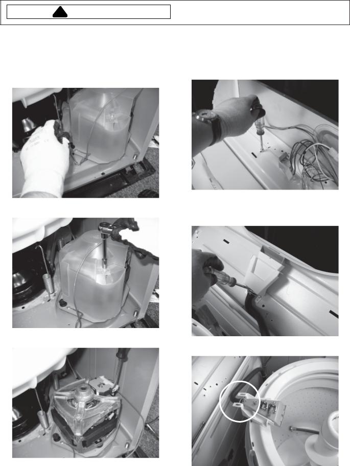
Water Valve Removal
1.Disconnect power supply to unit.
2.Lift Top Cover, see “top Cover Removal” procedure.
3.Remove retaining screw on back panel.
Dispenser Removal
1.Disconnect power supply to unit.
2.Lift Top Cover, see “Top Cover Removal” procedure.
3.Relieve tension on Dispenser retaining tab.
4. Lift Water Valve to align with cutout in back cabinet.
Front Panel Removal
1. Disconnect power supply to unit.
2. Lift Top Cover, see “Top Cover Removal” procedure. 3. Remove two screws, 1 each side on Front Panel top
edge.
©2005 Maytag Services |
16026502 |
21 |
Disassembly Procedures
!WARNING
To avoid risk of electrical shock, personal injury or death, disconnect power to unit before servicing.
Motor Removal
1.Disconnect power supply to unit.
2.Lift Top Cover, see “Top Cover Removal” procedure.
3.Remove Front Panel, see “Front Panel Removal” procedure.
4.Remove Motor ground wire.
Flume/Thermistor Removal
1.Disconnect power supply to unit.
2.Remove Console, see “Console Disassembly” procedure.
3.Remove Flume screw from top of Top Cover.
4. Lift Top Cover, see “Top Cover Removal” procedure. 5. Remove Motor Shield. 5. Remove two Flume retaining screws from bottom of
Top Cover.
6. Remove Motor wire harness connector.
6. Remove hose clamp and Flume/Diverter Hose.
7. Remove three screws retaining Motor to Base.
22 |
16026502 |
©2005 Maytag Services |
Disassembly Procedures
!WARNING
To avoid risk of electrical shock, personal injury or death, disconnect power to unit before servicing.
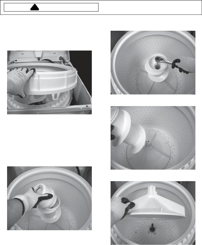
Tub Top Removal
1.Disconnect power supply to unit.
2.Lift Top Cover, see “Top Cover Removal” procedure.
3.Press down on Tub Top and swing locking latch away from Outer Tub. Repeat for all latches
4.Remove Tub Top.
6.Remove screw located in the center of the Agitator/ Auger assembly.
7. Remove Agitator Auger from Agitator Base.
Agitator/Spinner/Outer Tub/Transmission
Removal
1.Disconnect power supply to unit.
2.Remove Drain Pump hoses and Belt, see “Drain Pump/Belt Removal” procedure steps 1 - 4.
3.Lift Top Cover, see “Top Cover Removal” procedure.
4.Remove Tub Top, see “Tub Top Removal” procedure.
5.Unsnap Fabric Softener Dispenser from Agitator.
8. Lift Agitator Base from Washer.
©2005 Maytag Services |
16026502 |
23 |

Disassembly Procedures
!WARNING
To avoid risk of electrical shock, personal injury or death, disconnect power to unit before servicing.
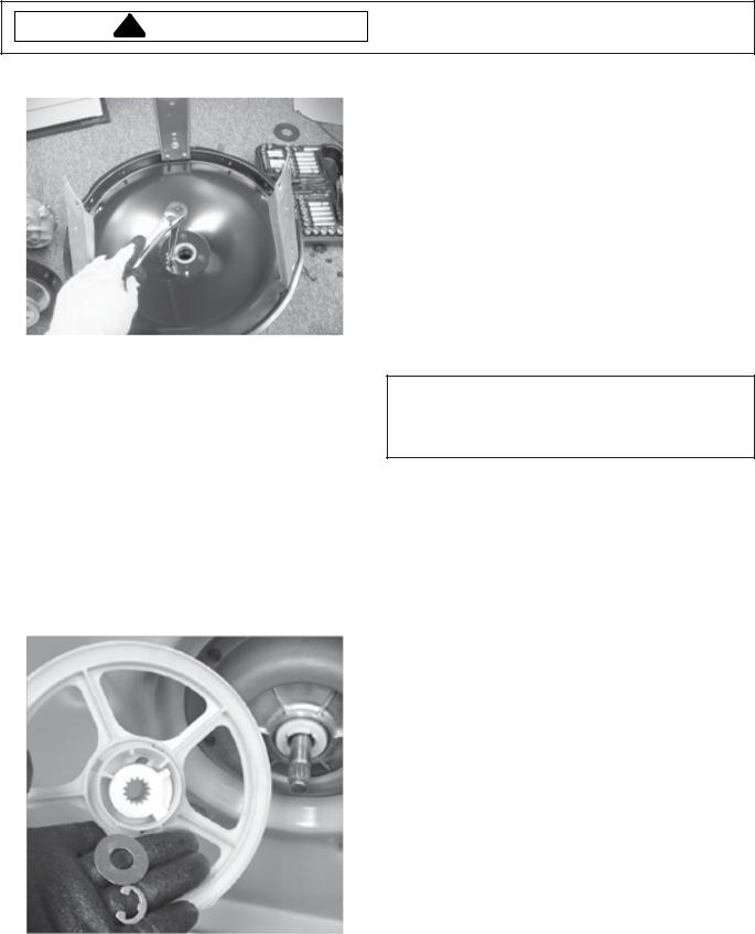
9. Remove four screws retaining Spinner (Inner Tub). |
13. Remove Pressure Switch Hose from fitting on Outer |
10.After Spinner (Inner Tub) is removed, use Spanner |
Tub. |
Wrench and Seal Nut tool to remove Seal Nut. |
|
11. Remove gasket from Hub.
14.Remove Suspension Springs using the spring removal tool. Be careful not to let Tub and Transmission assembly tip over.
12.Use Spanner Wrench to remove Hub.
24 |
16026502 |
©2005 Maytag Services |

Disassembly Procedures
!WARNING
To avoid risk of electrical shock, personal injury or death, disconnect power to unit before servicing.
15. Be sure to lay down a protective pad before removing |
17. Remove screws retaining Outer Tub to Transmission |
assembly. Remove Outer Tub and Transmission |
Support. |
assembly from Cabinet. Turn assembly over and stand |
|
on protective pad on Outer Tub rim. |
|
Tub Seal/Transmission Disassembly
1. Disconnect power supply to unit.
2. Remove Transmission Assembly from washer, see “Agitator/Spinner/Outer Tub/Transmission Removal” procedure.
3. Remove Transmission from Transmission Support by removing screws on Verticle Support Legs.
16.Mark location of Transmission Support with respect to the Outer Tub for ease of assembly.
©2005 Maytag Services |
16026502 |
25 |
Disassembly Procedures
!WARNING
To avoid risk of electrical shock, personal injury or death, disconnect power to unit before servicing.
4. Remove screws retaining the Tub Seal.
Drive Pulley and Cam Removal
The Drive Pulley and Cam are located below the Brake assembly on the drive shaft. A Washer and Retaining Ring secure the Pulley and Cam on the drive shaft. A plastic Dust Cap snaps to the underside of the Pulley to keep the Cam surfaces clean. These components can be removed by tipping the Washer back to access bottom side of unit.
1.Disconnect power supply to unit.
2.Remove (pry off) Dust Cap from under side of pulley.
3.Remove Retaining Ring and Washer from end of drive shaft.
4.Firmly pull Lower Cam off of the drive shaft splines, then slide the other parts off of the shaft.
Models are equipped with a plastic Drive Pulley which has the upper Cam molded onto the bottom of the Hub. The purpose of the Pulley and Cam arrangement is to drive the Clutch assembly during the agitate and spin cycle, and to disengage the Brake assembly during the spin cycle.
The Drive Pulley slips over the drive shaft and rests against a series of Washers, a Thrust Bearing, and a large washer type Spacer. The Spacer locates against the bottom of the Brake Rotor and Lining assembly. The Lower Cam slips over the end of the drive shaft where splines formed in the Cam engage with mating splines on the drive shaft end. This imparts a direct drive from the Cam to the drive shaft. A shoulder molded on the bottom of the Pulley hub engages "dogs" formed on the sides of the Lower Cam, and will drive it and the drive
shaft in either direction.
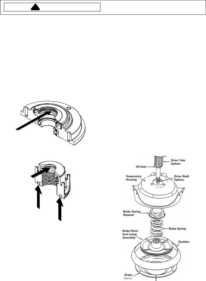
Brake Disassembly
The Brake assembly is located inside the domed area of the Suspension Housing and consists of the following components: Brake Spring Retainer, Brake Spring, Rotor and Lining assembly, and the Brake Stator.
CAUTION:The brake assembly has a compressive spring force of approximately 200 pounds. Use Brake Removal Tool LA-2004 or 12002012.
1.Disconnect power supply to unit.
2.Remove Transmission Assembly from Washer, see “Agitator/Spinner/Outer Tub/Transmission Removal” procedure.
3.Remove the Drive Pulley and Cam components, see “Drive Pulley and Cam Removal” procedure.
4.Pull out and remove "U" retainer from Brake Removal Tool.
5.Slip the splined end of the drive shaft into hole located in the tool inner plunger.
6.Looking at the side of the tool, align slots on tool barrel and holes in tool plunger between splines and chamfered shoulder of shaft.
7.Slip "U" retainer through tool slots and holes capturing the drive shaft behind the chamfered shoulder.
NOTE:Be sure "U" retainer is completely through both sides of tool.
8.Tighten tool nut to compress Brake Spring until Transmission turns freely.
9.Remove the six (6) screws which secure the Brake Stator and Snubber to the underside of the Suspension Housing.
10.Loosen tool nut until the Brake Spring reaches its free length.
11.Remove "U" retainer from tool and remove tool from drive shaft.
12.Remove Brake components.
NOTE: Be sure not to get any grease on Brake Snubber, Stater, or Brake Lining.
26 |
16026502 |
©2005 Maytag Services |
Disassembly Procedures
!WARNING
To avoid risk of electrical shock, personal injury or death, disconnect power to unit before servicing.
Tub Seal Replacement
1.Disconnect power supply to unit.
2.Remove Tub Seal, see “Tub Seal/Transmission Disassembly” procedure.
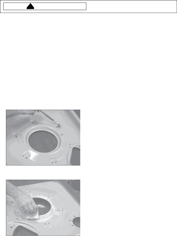
3.Make sure both mating surfaces on Transmission shaft are free of foreign matter, then clean both surfaces with an alcohol saturated cloth.
4.Apply a thin layer of grease to the locations indicated in the following images to Seal Nut and Triple Lip Seal before installing. Insure that no grease gets on Snubber, Stater, or Brake Lining.
NOTE: Do not use any agent other than alcohol to clean the mating surface. Do not use any lubricant other than
Silicone Grease, part number 203959.
Apply grease to location indicated with arrow on Triple Lip Seal.
Apply grease to locations indicated with arrows on Seal Nut.
Spin Bearing Replacement
1.Disconnect power supply to unit.
2.Press the Spin Bearing out of the cavity from the opposite side of the housing.
3.When installing the replacement bearing into the housing cavity, be sure to press against the outer race of the bearing to avoid damage to the bearing shield and causing premature failure.
Oil Seal Replacement
The Oil Seal is located in the spline end of the drive tube. The Oil Seal can be replaced without removing or disassembling the Transmission.
1.Disconnect power supply to unit.
2.Tip Washer back to access bottom side and remove Drive Belt, Dust Cap, Retaining Ring, Washer, Cam, Drive Pulley, Thrust Bearing and Spacer, see “Drive Pully and Cam Removal” procedure.
3.Remove the Brake assembly to access the Oil Seal, see “Brake Disassembly” procedure.
4.Use a thin, flat bladed screwdriver to carefully pry the old Oil Seal out.
5.Place the drive washer (tool number 14242) and the new Oil Seal over the seal protector.
6.Remove the cone-shaped end from the seal protector tool and slide the tool, drive washer, and new Oil Seal over the drive shaft up to the seal cavity.
7.Slide the Transmission seal driver (tool number 14242) over the drive shaft until it makes contact with the drive washer. Use the impact sleeve of the tool to "tap" the Oil Seal into the end of the drive tube.
Snubber/Brake Assembly
1.Disconnect power supply to unit.
2.Apply a small amount of grease to the splines of the Drive Tube and Rotor.
©2005 Maytag Services |
16026502 |
27 |

Disassembly Procedures
!WARNING
To avoid risk of electrical shock, personal injury or death, disconnect power to unit before servicing.
NOTE: This is a dry operating Brake assembly. Make sure no oil or grease comes in contact with the mating surfaces of the Brake Lining, Brake Stater, or Snubber.
3.Be sure to wash hands to remove any dirt or grease before handling Snubber. Clean new Snubber with alcohol before installing. When installing new Snubber, insure Snubber is centered.
4.Install Stator by locating the dimple on the Stator, and tightening the screw next to the dimple first.
Dimple
5.Next tighten the screw 180 degrees across from the dimple. Tighten remaining screws. Remove brake tool.
6.Reinstall Drive Pulley, Cam, Washer, Retaining Ring, and Dust Cap.
Drive Pulley hub travels upward, it compresses the Brake Spring and moves the Rotor and Lining assembly up the drive tube disengaging it from the Stator. The Transmission is now free to spin.
Splines in the Brake Rotor hub mesh with splines on the drive tube end to provide positive vertical movement for the Rotor and Lining assembly. The splines are greased for ease of movement.
Installing Thrust Bearing
1.Thrust Bearing and Spacer are to be assembled as shown.
2.Apply a thin layer of grease between the contacting surfaces of the Lower Cam and the Drive Pulley.
Grease
The Brake assembly, as well as the Snubber, is held in |
Base Replacement |
|||
1. Disconnect power supply to unit. |
||||
position by the Brake Stator which is secured to the |
|
|||
|
2. Remove Drain Pump and Belt, see “Drain Pump/Belt |
|||
underside of the Suspension Housing by six (6) |
|
|||
|
|
Removal” procedure. |
||
mounting screws. |
|
|
||
|
|
|
||
Spring pressure forces the Rotor and Lining assembly |
NOTE: There may be water remaining in the hose from |
|||
|
the last cycle. |
|||
down on the Brake Stator and prevents the Transmission |
|
|||
|
|
|||
from turning during agitation. |
|
3. Lift Top Cover, see “Top Cover Removal” procedure. |
||
|
|
|||
As stated previously, the Drive Pulley and Cams provide |
4. |
Remove Front Panel, see “Front Panel Removal” |
||
a cam action which raises the Drive Pulley during the |
|
|
procedure. |
|
counterclockwise (spin) direction of the Motor. When the |
5. |
Remove Motor, see “Motor Removal” procedure. |
||
28 |
16026502 |
©2005 Maytag Services |
||
Disassembly Procedures
!WARNING
To avoid risk of electrical shock, personal injury or death, disconnect power to unit before servicing.
6.Remove Pressure Switch hose, Tub Springs and Outer Tub/Transmission assembly, see “Agitator/ Spinner/Outer Tub/Transmission Removal” procedure steps 13, 14 and 16.
7.Remove screws from sides and rear of unit around bottom, connecting Cabinet to Base. Remove Cabinet from Base and set aside. Be sure to lay down a protective pad before removing Tub and Transmission assembly from Base. Remove Tub and Transmission assembly, turn over and lay on protective pad.
8.Remove Dust Cap, Retaining Ring, Washer, Cam, and Drive Pulley from bottom of Transmission, see “Drive Pully and Cam Removal” procedure.
9.Remove Brake assembly from Transmission, see “Brake Disassembly” procedure steps 4 - 12. Remove old Snubber from Transmission.
10.Install new Snubber, see “Snubber/Brake Assembly” procedure steps 3 - 6. Insure Snubber is centered.
11.Turn new Base upside down and apply grease at bottom of the spring hole pockets to eliminate noise between Spring and Base interaction.
12.Clean the dome area of new Base with alcohol then apply corn starch.
13.Reinstall Motor and Pump to new Base.
14.Transfer Transmission and Outer Tub onto new Base. Attach Suspension Springs using spring tool to avoid over stretching the Springs.
15.Transfer Cabinet shell onto new Base and reassemble Washer. Be sure to reattach Pressure Switch Hose to back of Tub, Drain Pump Hoses with clamps to Drain Pump, and wire harness to Motor. Check all hoses and wires to make sure they are secure.
16.Test Washer.
Transmission Operation
When the Drive Pulley rotates CLOCKWISE, the upper and lower cams are designed to nest together which allows the Drive Pulley to remain in position on the drive shaft. The Break remains engaged and the Drive Pulley will turn the lower cam and drive the shaft to cause the Transmission to agitate.
When the Drive Pulley rotates COUNTERCLOCKWISE, the upper cam and Pulley ride up the lower cam approximately 3/16 of an inch before the driving shoulders on the Pulley hub engage the "dogs" on the lower cam.
This causes the top of the Pulley hub to push against the Spacer which compresses the Brake Spring and lifts the Brake Rotor and Lining assembly off the Brake Stator.
The Brake is disengaged and the Pulley will turn the lower cam and drive shaft to cause the Transmission to spin.
Determine Brake Rotor Condition
Watch the Spacer on the Encapsulated Thrust Bearing. If the Spacer rotates with the Pulley, the Brake is functioning properly. If the Spacer stays stationary while rotating the Pulley to release the Brake, the Brake Rotor must be replaced.
After reassembling the Washer, fill the Tub with water and select a spin to drain the Tub. When the cycle is finished, verify the adjustment of the Brake, and verify the Spacer on the Thrust Bearing rotates with the Pulley.
Brake Adjustment
1.After reassembling the components on the drive shaft, it may be necessary to pull down on the shaft to take the endplay out before the Thrust Washer and Retaining Ring can be reinstalled.
NOTE: Each time the cams are reassembled on the drive shaft, the point in the cam rise where the Brake disengages the Stator should be checked and adjusted as necessary. Reference points have been molded into the Pulley as an aid in checking the point of Brake disengagement.
©2005 Maytag Services |
16026502 |
29 |
Disassembly Procedures
!WARNING
To avoid risk of electrical shock, personal injury or death, disconnect power to unit before servicing.
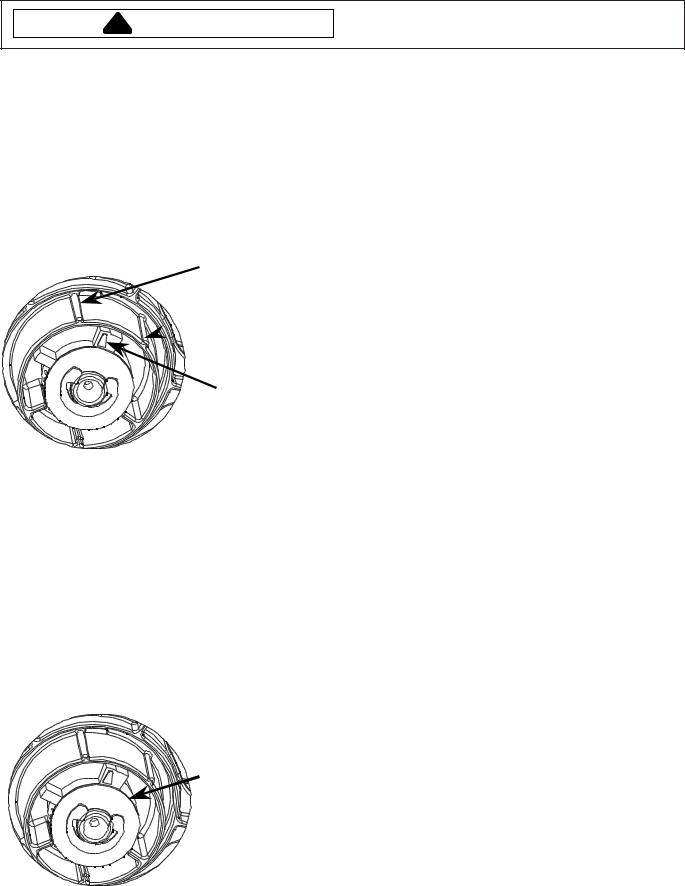
To Check Brake Disengagement
1.Manually rotate the Drive Pulley in a slow counterclockwise direction until the Brake starts to release and the Transmission begins to turn.
2.Position the “Reference Cam Arrow” midway between the “Min Pulley Hub Reference” and the “Max Pulley Hub Reference” markers located on the Pulley.
If the position of the Cam Arrow to the Pulley Hub is not within these parameters adjustment is required.
Min Pulley Hub
Reference
Max Pulley Hub
 Reference
Reference Cam
Arrow
To Adjust Brake Disengagement
1.If the position of the Cam Reference Arrow is less than the Min Pulley Hub reference mark, remove the standard (.062 thickness) Thrust Washer and replace it with a thinner (.032 thickness) Thrust Washer. Recheck disengagement 3 times to verify proper adjustment.
2.If the position of the Cam Reference Arrow is more than the Max Pulley Hub reference mark, add a (.032 thickness) Thrust Washer to the standard Thrust Washer. Recheck disengagement 3 times to verify proper adjustment.
Thrust Washer
Placement
30 |
16026502 |
©2005 Maytag Services |
 Loading...