


Operating Instructions
Pressure transmitter with CERTEC® measuring cell
VEGABAR 52
4 … 20 mA
Document ID: 36716

Contents
Contents
1 About this document |
4 |
|
1.1 |
Function............................................................................................................................ |
|
1.2 |
Target group...................................................................................................................... |
4 |
1.3 |
Symbolism used............................................................................................................... |
4 |
2 For your safety |
5 |
|
2.1 |
Authorised personnel........................................................................................................ |
|
2.2 |
Appropriate use................................................................................................................ |
5 |
2.3 |
Warning about incorrect use............................................................................................. |
5 |
2.4 |
General safety instructions................................................................................................ |
5 |
2.5 |
Safety label on the instrument........................................................................................... |
5 |
2.6 |
CE conformity................................................................................................................... |
6 |
2.7 |
Measuring range - permissible process pressure............................................................. |
6 |
2.8 |
Fulfillment of NAMUR recommendations.......................................................................... |
6 |
2.9 |
Safety instructions for Ex areas......................................................................................... |
6 |
2.10 |
Environmental instructions................................................................................................ |
6 |
3 Product description |
7 |
|
3.1 |
Configuration.................................................................................................................... |
|
3.2 |
Principle of operation........................................................................................................ |
8 |
3.3 |
Operation.......................................................................................................................... |
9 |
3.4 |
Packaging, transport and storage..................................................................................... |
9 |
3.5 |
Accessories and replacement parts................................................................................ |
10 |
4 Mounting |
11 |
|
4.1 |
General instructions........................................................................................................ |
|
4.2 |
Mounting steps............................................................................................................... |
13 |
4.3 |
Mounting steps, external housing................................................................................... |
13 |
5 Connecting to power supply |
15 |
|
5.1 |
Preparing the connection................................................................................................ |
|
5.2 |
Connection procedure.................................................................................................... |
16 |
5.3 |
Wiring plan, single chamber housing.............................................................................. |
17 |
5.4 |
Wiring plan - version IP 66/IP 68, 1 bar........................................................................... |
18 |
5.5 |
Wiring plan, external housing with version IP 68............................................................. |
19 |
5.6 |
Switch-on phase............................................................................................................. |
20 |
6 Set up with the display and adjustment module PLICSCOM |
21 |
|
6.1 |
Short description............................................................................................................. |
|
6.2 |
Insert display and adjustment module............................................................................. |
21 |
6.3 |
Adjustment system.......................................................................................................... |
22 |
6.4 |
Setup steps..................................................................................................................... |
23 |
6.5 |
Menu schematic............................................................................................................. |
31 |
7 Set up with PACTware and other adjustment programs |
34 |
|
7.1 |
Connect the PC via VEGACONNECT............................................................................. |
|
7.2 |
Parameter adjustment with PACTware............................................................................ |
34 |
8Maintenance and fault rectification
8.1 |
Maintain.......................................................................................................................... |
35 |
|
8.2 |
Rectify faults................................................................................................................... |
35 |
|
8.3 |
Calculation of total deviation (according to DIN 16086).................................................. |
36 |
|
|
|
|
|
2 |
|
VEGABAR 52 • 4 … 20 mA |
|
130321-EN-36716

36716-EN-130321
|
|
|
|
Contents |
|
|
8.4 |
Exchanging the electronics module |
................................................................................ 38 |
||
|
8.5 |
Software update.............................................................................................................. |
38 |
||
|
8.6 |
Instrument repair............................................................................................................. |
39 |
||
9 |
Dismounting |
40 |
|||
|
9.1 |
Dismounting steps.......................................................................................................... |
|||
|
9.2 |
Disposal.......................................................................................................................... |
40 |
||
10 |
Supplement |
41 |
|||
|
10.1 |
Technical data................................................................................................................. |
|||
|
10.2 |
Dimensions..................................................................................................................... |
50 |
||
Supplementary documentation
Information:
Supplementary documents appropriate to the ordered version come with the delivery.You can find them listed in chapter "Product description".
Editing status: 2013-03-11
VEGABAR 52 • 4 … 20 mA |
3 |
1 About this document
1 About this document
1.1Function
This operating instructions manual provides all the information you need for mounting, connection and setup as well as important instructions for maintenance and fault rectification.Please read this information before putting the instrument into operation and keep this manual accessible in the immediate vicinity of the device.
1.2Target group
This operating instructions manual is directed to trained specialist personnel. The contents of this manual should be made available to these personnel and put into practice by them.
1.3Symbolism used
•
→
Information, tip, note
This symbol indicates helpful additional information.
Caution: If this warning is ignored, faults or malfunctions can result.
Warning: If this warning is ignored, injury to persons and/or serious damage to the instrument can result.
Danger: If this warning is ignored, serious injury to persons and/or destruction of the instrument can result.
Ex applications
This symbol indicates special instructions for Ex applications.
List
The dot set in front indicates a list with no implied sequence.
Action
This arrow indicates a single action.
1Sequence
Numbers set in front indicate successive steps in a procedure.
Battery disposal
This symbol indicates special information about the disposal of batteries and accumulators.
130321-EN-36716
4 |
VEGABAR 52 • 4 … 20 mA |

36716-EN-130321
2 For your safety
2 For your safety
2.1Authorised personnel
All operations described in this operating instructions manual must be carried out only by trained specialist personnel authorised by the plant operator.
During work on and with the device the required personal protective equipment must always be worn.
2.2Appropriate use
VEGABAR 52 is a pressure transmitter for measurement of gauge pressure, absolute pressure and vacuum.
You can find detailed information on the application range in chapter "Product description".
Operational reliability is ensured only if the instrument is properly used according to the specifications in the operating instructions manual as well as possible supplementary instructions.
For safety and warranty reasons, any invasive work on the device beyond that described in the operating instructions manual may be carried out only by personnel authorised by the manufacturer. Arbitrary conversions or modifications are explicitly forbidden.
2.3Warning about incorrect use
Inappropriate or incorrect use of the instrument can give rise to application-specific hazards, e.g.vessel overfill or damage to system components through incorrect mounting or adjustment.
2.4General safety instructions
This is a high-tech instrument requiring the strict observance of standard regulations and guidelines. The user must take note of the safety instructions in this operating instructions manual, the country-specific installation standards as well as all prevailing safety regulations and accident prevention rules.
The instrument must only be operated in a technically flawless and reliable condition. The operator is responsible for trouble-free operation of the instrument.
During the entire duration of use, the user is obliged to determine the compliance of the necessary occupational safety measures with the current valid rules and regulations and also take note of new regulations.
2.5Safety label on the instrument
The safety approval markings and safety tips on the device must be observed.
VEGABAR 52 • 4 … 20 mA |
5 |

2 For your safety
2.6CE conformity
This device fulfills the legal requirements of the applicable EC guidelines.By attaching the CE mark,VEGA provides a confirmation of successful testing.You can find the CE conformity declaration in the download area of "www.vega.com".
2.7Measuring range - permissible process pressure
Due to the application, a measuring cell with a measuring range higher than the permissible pressure range of the process fitting may have been integrated. The permissible process pressure is stated with
"Process pressure" on the type label, see chapter 3.1 "Configuration".
For safety reasons, this range must not be exceeded.
2.8Fulfillment of NAMUR recommendations
The device fulfills the requirements of the applicable NAMUR recommendations.
2.9Safety instructions for Ex areas
Please note the Ex-specific safety information for installation and operation in Ex areas. These safety instructions are part of the operating instructions manual and come with the Ex-approved instruments.
2.10 Environmental instructions
Protection of the environment is one of our most important duties. That is why we have introduced an environment management system with the goal of continuously improving company environmental protection.The environment management system is certified according to DIN EN ISO 14001.
Please help us fulfill this obligation by observing the environmental instructions in this manual:
•Chapter "Packaging, transport and storage"
•Chapter "Disposal"
130321-EN-36716
6 |
VEGABAR 52 • 4 … 20 mA |
3 Product description
3 Product description
3.1Configuration
Scope of delivery |
The scope of delivery encompasses: |
||
|
• |
VEGABAR 52 process pressure transmitter |
|
|
• |
Documentation |
|
|
–– |
this operating instructions manual |
|
|
|
–– |
Test certificate for pressure transmitters |
|
|
–– |
Safety Manual 31637 "VEGABAR series 50 and 60 - |
|
|
–– |
4 … 20 mA/HART" (optional) |
|
|
Operating instructions manual 27835 "Display and adjustment |
|
|
|
–– |
module PLICSCOM" (optional) |
|
|
Supplementary instructions manual 31708 "Heating for display |
|
|
|
–– |
and adjustment module" (optional) |
|
|
Supplementary instructions manual "Plug connector for con- |
|
|
|
–– |
tinuously measuring sensors" (optional) |
|
|
Ex-specific "Safety instructions" (with Ex versions) |
|
|
|
–– |
if necessary, further certificates |
Constituent parts |
The VEGABAR 52 consists of the components: |
|
|
• |
Process fitting with measuring cell |
|
• |
Housing with electronics, optionally available with plug connector |
|
• |
Housing cover, optionally available with display and adjustment |
|
|
module |
|
The components are available in different versions. |
|
|
|
1 |
|
|
2 |
|
|
3 |
36716-EN-130321
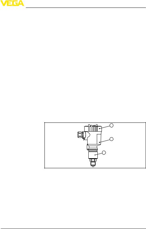
Fig.1:Example of aVEGABAR 52 with manometer connection G½ A according to EN 837 and plastic housing
|
1 |
Housing cover with integrated display and adjustment module (optional) |
|
2 |
Housing with electronics |
|
3 |
Process fitting with measuring cell |
Type plate |
The nameplate contains the most important data for identification and |
|
|
use of the instrument: |
|
VEGABAR 52 • 4 … 20 mA |
7 |
3 Product description
Scope of this operating instructions manual
Application area
Functional principle
8
1 |
2 |
14 |
|
13 |
||
3 |
||
|
4 |
5 |
|
|
6 |
12 |
|
7 |
||
11 |
||
8 |
||
|
||
9 |
10 |
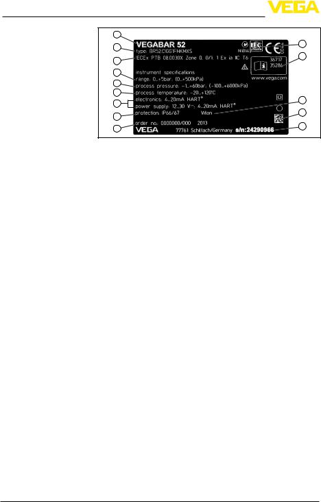
Fig.2:Layout of the type label (example)
1 Instrument type
2 Product code
3Approvals
4 Measuring range
5 Process pressure
6Process temperature
7 Electronics, voltage supply
8 Protection rating
9 Order number
10Serial number
11Data-Matrix-Code for Smartphone-App
12Material process seal
13ID numbers, instrument documentation
14Notified authority for CE marking
With the serial number, you can access the delivery data of the instrument via www.vega.com, "VEGATools" and "serial number search". In addition to the type label outside, you can also find the serial number on the inside of the instrument.
This operating instructions manual applies to the following instrument versions:
• Software from 3.82
3.2Principle of operation
VEGABAR 52 is a pressure transmitter for use in the paper, food processing and pharmaceutical industries as well as in water/sewage water plants. Depending on the version, it is used for level, gauge, absolute pressure or vacuum measurement. Measured products are gases, vapours and liquids, also those containing abrasive substances.
Sensor element is the CERTEC® measuring cell with robust, dependent on the process fitting also front-flush, abrasion-resistant ceramic diaphragm. The process pressure causes a capacitance change in the measuring cell via the ceramic diaphragm. This change is converted into an appropriate output signal and outputted as measured value.
VEGABAR 52 • 4 … 20 mA
130321-EN-36716

36716-EN-130321
|
|
|
3 Product description |
|
|
|
The CERTEC® measuring cell is also equipped with a temperature |
||
|
|
sensor. The temperature value can be displayed via the display and |
||
|
|
adjustment module as well as processed via the signal output (with |
||
|
|
digital versions). |
||
Seal concept |
As a standard feature, the CERTEC® measuring cell is equipped with |
|||
|
|
a lateral, recessed seal. |
||
|
|
Instruments with double seal have an additional front seal. |
||
|
|
Instruments with hygienic fitting are equipped with a gap-free form |
||
|
|
seal. |
||
Voltage supply |
4 … 20 mA two-wire electronics for voltage supply and measured |
|||
|
|
value transmission on the same cable. |
||
|
|
The supply voltage range can differ depending on the instrument ver- |
||
|
|
sion.The exact range is stated in chapter "Technical data". |
||
|
|
The backlight of the display and adjustment module is powered by |
||
|
|
the sensor. The prerequisite for this is a supply voltage at a certain |
||
|
|
level.The exact voltage specifications are stated in chapter "Technical |
||
|
|
data". |
||
|
|
The optional heating requires its own operating voltage.You can find |
||
|
|
details in the supplementary instructions manual "Heating for display |
||
|
|
and adjustment module". |
||
|
|
This function is generally not available for approved instruments. |
||
|
|
3.3 Operation |
||
|
|
The instrument can be adjusted with the following adjustment media: |
||
|
|
• |
With the display and adjustment module |
|
|
|
• |
with the suitable VEGA DTM in conjunction with an adjustment |
|
|
|
software according to the FDT/DTM standard, e.g. PACTware and |
||
|
|
|
PC |
|
|
|
3.4 Packaging, transport and storage |
||
Packaging |
Your instrument was protected by packaging during transport. Its |
|||
|
|
capacity to handle normal loads during transport is assured by a test |
||
|
|
based on ISO 4180. |
||
|
|
The packaging of standard instruments consists of environment- |
||
|
|
friendly, recyclable cardboard. For special versions, PE foam or PE |
||
|
|
foil is also used. Dispose of the packaging material via specialised |
||
|
|
recycling companies. |
||
Transport |
Transport must be carried out under consideration of the notes on the |
|||
|
|
transport packaging. Nonobservance of these instructions can cause |
||
|
|
damage to the device. |
||
Transport inspection |
The delivery must be checked for completeness and possible transit |
|||
|
|
damage immediately at receipt. Ascertained transit damage or con- |
||
|
|
cealed defects must be appropriately dealt with. |
||
|
|
|
||
VEGABAR 52 • 4 … 20 mA |
|
9 |
||

3 Product description
Storage |
Up to the time of installation, the packages must be left closed and |
|
|
stored according to the orientation and storage markings on the |
|
|
outside. |
|
|
Unless otherwise indicated, the packages must be stored only under |
|
|
the following conditions: |
|
|
• |
Not in the open |
|
• |
Dry and dust free |
|
• |
Not exposed to corrosive media |
|
• |
Protected against solar radiation |
|
• |
Avoiding mechanical shock and vibration |
Storage and transport |
• |
Storage and transport temperature see chapter "Supplement - |
temperature |
Technical data - Ambient conditions" |
|
|
• |
Relative humidity 20 … 85 % |
|
3.5 Accessories and replacement parts |
|
Display and adjustment |
The display and adjustment module PLICSCOM is used for measured |
|
module |
value indication, adjustment and diagnosis. It can be inserted into the |
|
|
sensor and removed at any time. |
|
|
You can find further information in the operating instructions "Display |
|
|
and adjustment module PLICSCOM" (Document-ID 27835). |
|
Flanges |
Flanges are available in different versions according to the following |
|
|
standards: DIN 2501, EN 1092-1, ANSI B 16.5, JIS B 2210-1984, |
|
|
GOST 12821-80. |
|
|
You can find additional information in the supplementary instructions |
|
|
manual "Flanges according to DIN-EN-ASME-JIS" (Document-ID |
|
|
31088). |
|
Measuring instrument |
The measuring instrument holder is used for wall/tube mounting of |
|
holder |
VEGABAR series 50 pressure transmitters and VEGAWELL 52 sus- |
|
|
pension pressure transmitters. Supplied reducers enable the adapta- |
|
|
tion to different instrument diameters.The material used is 316L. |
|
Protective cover |
The protective cover protects the sensor housing against soiling and |
|
|
intense heat from solar radiation. |
|
|
You will find additional information in the supplementary instructions |
|
|
manual "Protective cover" (Document-ID 34296). |
|
Electronics module |
The electronics module is a replacement part for pressure transmitter |
|
|
VEGABAR. One version is available for each type of signal output. |
|
You find further information in the operating instructions "Electronics moduleVEGABAR series 50 and 60 " (Document-ID 30175).
130321-EN-36716
10 |
VEGABAR 52 • 4 … 20 mA |
|
|
|
4 Mounting |
|
|
4 |
Mounting |
|
|
4.1 |
General instructions |
Suitability for the process |
Make sure that all parts of the instrument coming in direct contact |
||
conditions |
with the process, especially the sensor element, process seal and |
||
|
|
process fitting, are suitable for the existing process conditions, such |
|
|
|
as process pressure, process temperature as well as the chemical |
|
|
|
properties of the medium. |
|
|
|
You can find the specifications in chapter "Technical data" and on the |
|
|
|
nameplate. |
|
Installation position |
Select an installation position you can easily reach for mounting and |
||
|
|
connecting as well as later retrofitting of a display and adjustment |
|
|
|
module. The housing can be rotated by 330° without the use of any |
|
|
|
tools.You can also install the display and adjustment module in four |
|
|
|
different positions (each displaced by 90°). |
|
Moisture |
Use the recommended cables (see chapter "Connecting to power |
||
|
|
supply") and tighten the cable gland. |
|
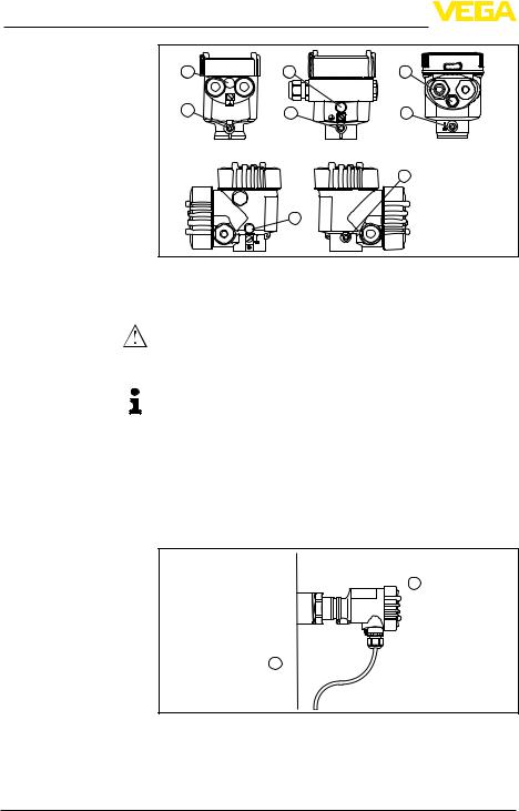
You can give your instrument additional protection against moisture penetration by leading the connection cable downward in front of the cable entry.Rain and condensation water can thus drain off.This applies mainly to outdoor mounting as well as installation in areas where high humidity is expected (e.g. through cleaning processes) or on cooled or heated vessels.
Fig.3:Measures against moisture penetration
Ventilation and pressure The ventilation of the electronics housing as well as the atmospheric compensation pressure compensation for the measuring cell are realised via a filter element in the area of the cable gland.
36716-EN-130321
VEGABAR 52 • 4 … 20 mA |
11 |
4 Mounting
1 |
1 |
1 |
2 |
2 |
2 |
|
|
2 |
|
1 |
|
Fig.4:Position of the filter element 1 Filter element
2Blind plug
Caution:
Due to the filter effect, the pressure compensation is time delayed.
When opening/closing the housing cover quickly, the measured value can change for a period of approx. 5 s by up to 15 mbar.
Information:
Make sure that the filter element is always free of buildup during operation. A high-pressure cleaner may not be used for cleaning.
With instrument versions in protection IP 66/IP 68, 1 bar, the ventilation is realised via the capillaries in the permanently connected cable.
The filter element is replaced by a blind plug.
Temperature limits |
Higher process temperatures often mean also higher ambient |
|
temperatures. Make sure that the upper temperature limits stated in |
|
chapter "Technical data" for the environment of the electronics hous- |
|
ing and connection cable are not exceeded. |
1
Fig.5:Temperature ranges
1 Process temperature
2 Ambient temperature
12
2
130321-EN-36716
VEGABAR 52 • 4 … 20 mA
36716-EN-130321
|
|
4 Mounting |
|
|
4.2 Mounting steps |
Welding the socket |
For mountingVEGABAR 52, a welded socket is required.You can find |
|
|
|
these components in the supplementary instructions manual "Welded |
|
|
socket and seals". |
Sealing/Screwing in threaded versions
Sealing/Screwing in flange versions
Sealing/Screwing in hygienic fittings
Use the seal fitting belonging to the instrument, or in case of NPT connections, a high-resistance sealing material.
→Screw VEGABAR 52 into the welded socket. Tighten the hexagon on the process fitting with a suitable wrench.Wrench size, see chapter "Dimensions".
Warning:
The housing must not be used to screw the instrument in! Applying tightening force can damage internal parts of the housing.
Seal the flange connections according to DIN/ANSI with a suitable, resistant seal and mount VEGABAR 52 with suitable screws.
Use the seal suitable for the respective process fitting.You can find the components in the supplementary instructions manual "Welded socket and seals".
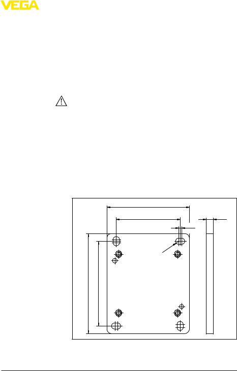
4.3Mounting steps, external housing
Wall mounting |
1. Mark the holes according to the following drilling template |
2.Depending on the mounting surface, fasten the wall mounting plate with 4 screws
|
90 mm (3.54") |
|
|
|
70 mm (2.76") |
|
8 mm |
|
|
3mm |
(0.32") |
|
|
|
|
|
|
(0.12") |
|
|
|
mm |
|
|
3,5 |
|
|
|
R |
.14") |
|
|
|
(0 |
|
110 mm (4.33") |
93 mm (3.66") |
|
|
Fig.6:Drilling template - wall mounting plate
VEGABAR 52 • 4 … 20 mA |
13 |
4 Mounting
Tip:
Mount the wall mounting plate so that the cable entry of the socket housing points downward. The socket housing can be displaced by 180° to the wall mounting plate.
Warning:
The four screws of the socket housing must only be hand screwed. A torque > 5 Nm (3.688 lbf ft) can damage the wall mounting plate.
130321-EN-36716
14 |
VEGABAR 52 • 4 … 20 mA |

36716-EN-130321
|
|
|
|
|
|
|
5 Connecting to power supply |
|
|
|
|
|
|
|
5 Connecting to power supply |
||
|
|
|
|
|
|
5.1 Preparing the connection |
||
Safety instructions |
Always keep in mind the following safety instructions: |
|||||||
|
|
|
|
|
|
• |
Connect only in the complete absence of line voltage |
|
|
|
|
|
|
|
• |
If overvoltage surges are expected, overvoltage arresters should |
|
|
|
|
|
|
|
|
be installed |
|
|
|
|
|
|
|
Tip: |
||
|
|
|
|
|
|
We recommend using VEGA overvoltage arresters B63-48 and |
||
|
|
|
|
|
|
ÜSB 62-36G.X. |
||
|
|
|
|
|
|
In hazardous areas you must take note of the respective regulations, |
||
|
|
|
|
|
|
conformity and type approval certificates of the sensors and power |
||
|
|
|
|
|
|
supply units. |
||
Voltage supply |
Power supply and current signal are carried on the same two-wire |
|||||||
|
|
|
|
|
|
cable.The voltage supply range can differ depending on the instru- |
||
|
|
|
|
|
|
ment version. |
||
|
|
|
|
|
|
The data for power supply are specified in chapter "Technical data". |
||
|
|
|
|
|
|
Provide a reliable separation between the supply circuit and the |
||
|
|
|
|
|
|
mains circuits according to DIN EN 61140 VDE 0140-1. The VEGA |
||
|
|
|
|
|
|
power supply units VEGATRENN 149A Ex, VEGASTAB 690 as well |
||
|
|
|
|
|
|
as all VEGAMETs and VEGASCANs meet this requirement. |
||
|
|
|
|
|
|
Keep in mind the following additional factors that influence the operat- |
||
|
|
|
|
|
|
ing voltage: |
||
|
|
|
|
|
|
• |
Output voltage of the power supply unit can be lower under nomi- |
|
|
|
|
|
|
|
nal load (with a sensor current of 20.5 mA or 22 mA in case of fault |
||
|
|
|
|
|
|
• |
message) |
|
|
|
|
|
|
|
Influence of additional instruments in the circuit (see load values in |
||
|
|
|
|
|
|
|
chapter "Technical data") |
|
Connection cable |
The instrument is connected with standard two-wire cable without |
|||||||
|
|
|
|
|
|
screen. If electromagnetic interference is expected which is above the |
||
|
|
|
|
|
|
test values of EN 61326 for industrial areas, screened cable should |
||
|
|
|
|
|
|
be used. |
||
|
|
|
|
|
|
Use cable with round cross-section.A cable outer diameter of |
||
|
|
|
|
|
|
5 … 9 mm (0.2 … 0.35 in) ensures the seal effect of the cable gland. |
||
|
|
|
|
|
|
If you are using cable with a different diameter or cross-section, |
||
|
|
|
|
|
|
exchange the seal or use a suitable cable gland. |
||
|
|
|
|
|
|
We generally recommend the use of screened cable for HART multi- |
||
|
|
|
|
|
|
drop mode. |
||
Cable gland ½ NPT |
On the instrument with cable entry ½ NPT and plastic housing there is |
|||||||
|
|
|
|
|
|
a metallic ½" threaded insert moulded into the plastic housing. |
||
|
|
|
|
|
|
Caution: |
||
|
|
|
|
|
|
No grease should be used when screwing the NPT cable gland or |
||
|
|
|
|
|
|
steel tube into the threaded insert. Standard grease can contain |
||
|
|
|
|
|
|
additives that corrode the connection between threaded insert and |
||
|
|
|
|
|
|
|
||
VEGABAR 52 • 4 … 20 mA |
|
15 |
||||||
5 Connecting to power supply
Cable screening and grounding
housing.This would influence the stability of the connection and the tightness of the housing.
If screened cable is necessary, connect the cable screen on both ends to ground potential. In the sensor, the screen must be connected directly to the internal ground terminal. The ground terminal on the outside of the housing must be connected to the potential equalisation (low impedance).
If potential equalisation currents are expected, the connection on the processing side must be made via a ceramic capacitor (e. g. 1 nF, 1500 V). The low-frequency potential equalisation currents are thus suppressed, but the protective effect against high frequency interference signals remains.
Warning:
Considerable potential differences exist inside galvanic plants as well as vessels with cathodic corrosion protection. Very large equalisation currents can flow through the cable screen when the screen
is grounded on both ends. To avoid this, the cable screen must be connected to ground potential only on one end (inside the switching cabinet) in such applications. The cable screen must not be connected to the internal ground terminal in the sensor and the outer ground terminal on the housing not to potential equalisation!
Information:
The metallic parts of the instrument (transmitter, process fitting, etc.) are conductively connected with the inner and outer ground terminal on the housing. This connection exists either as a direct metallic contact or via the shielding of the special connection cable on instruments with external electronics.You can find specifications on the potential connections within the instrument in chapter "Technical data".
Take note of the corresponding installation regulations for Ex applications. In particular, make sure that no potential equalisation currents flow over the cable screen.In case of grounding on both sides this can be achieved by the use of a capacitor or a separate potential equalisation.
Single/Double chamber housing
5.2Connection procedure
Proceed as follows:
1.Unscrew the housing cover
2.If a display and adjustment module is installed, remove it by turning it to the left.
3.Loosen compression nut of the cable entry
4.Remove approx. 10 cm of the cable mantle, strip approx. 1 cm insulation from the individual wires
5.Insert the cable into the sensor through the cable entry
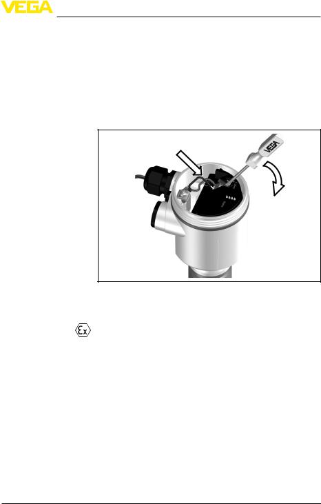
6.Lift the opening levers of the terminals with a screwdriver (see following illustration)
7.Insert the wire ends into the open terminals according to the wiring plan
16 |
VEGABAR 52 • 4 … 20 mA |
130321-EN-36716
5 Connecting to power supply
8.Press down the opening levers of the terminals, you will hear the terminal spring closing
9.Check the hold of the wires in the terminals by lightly pulling on them
10.Connect the screen to the internal ground terminal, connect the outer ground terminal to potential equalisation
11.Tighten the compression nut of the cable entry. The seal ring must completely encircle the cable
12.Screw the housing cover back on
The electrical connection is hence finished.
Fig.7:Connection steps 6 and 7
5.3Wiring plan, single chamber housing
The following illustrations apply to the non-Ex as well as to the Ex-ia version.
36716-EN-130321
VEGABAR 52 • 4 … 20 mA |
17 |

5 Connecting to power supply
Electronics and connection compartment
4...20mA |
Display |
|
1 |
1 |
2 |
2
Fig.8:Electronics and connection compartment, single chamber housing
1Spring-loaded terminals for voltage supply
2Ground terminal for connection of the cable screen
Wiring plan
4...20mA |
Display |
|
1 2
1 

Fig.9:Wiring plan, single chamber housing
1Voltage supply/Signal output
5.4Wiring plan - version IP 66/IP 68, 1 bar
Wire assignment, connection cable
1
2
Fig.10:Wire assignment, connection cable
1 brown (+) and blue (-) to power supply or to the processing system
2Shielding
130321-EN-36716
18 |
VEGABAR 52 • 4 … 20 mA |
5 Connecting to power supply
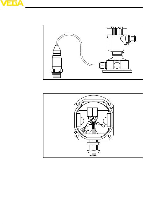
5.5Wiring plan, external housing with version IP 68
Overview
Fig.11:VEGABAR 52 in IP 68 version 25 bar and axial cable outlet, external housing
Terminal compartment, housing socket
1 2 3 4
1 2 3 4
5 6
Fig.12:Connection of the sensor in the housing socket 1 Brown
2Blue
3 Yellow
4White
5Shielding
6Breather capillaries
36716-EN-130321
VEGABAR 52 • 4 … 20 mA |
19 |
5 Connecting to power supply
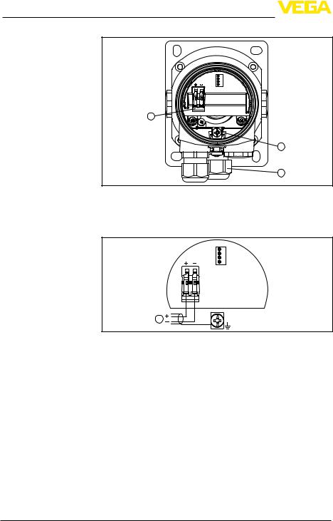
Electronics and connection compartment for power supply
4...20mA |
Display |
|
1 |
1 |
2 |
|
|
2
3
Fig.13:Electronics and connection compartment
1Spring-loaded terminals for voltage supply
2 Ground terminal for connection of the cable screen
3Cable gland to the sensor
Wiring plan external |
|
|
|
|
electronics |
|
4...20mA |
|
|
|
|
Display |
||
|
|
|
|
|
|
|
1 |
2 |
|
|
|
1 |
|
|
|
Fig.14:Wiring plan external electronics |
|
||
|
1 |
Voltage supply/Signal output |
|
|
|
5.6 Switch-on phase |
|
||
Switch-on phase |
After connecting VEGABAR 52 to power supply or after a voltage |
|||
|
recurrence, the instrument carries out a self-check for approx. 30 |
|||
|
seconds: |
|
|
|
|
• |
Internal check of the electronics |
|
|
|
• |
Indication of the instrument type, the firmware as well as the sen- |
||
|
sor TAGs (sensor designation) |
|
||
|
• |
Output signal jumps briefly (approx.10 seconds) to the set fault |
||
|
|
current |
|
|
|
Then the corresponding current is outputted to the cable (the value |
|||
|
corresponds to the actual level as well as the settings already carried |
|||
|
out, e.g. factory setting). |
|
|
|
20 |
|
|
|
VEGABAR 52 • 4 … 20 mA |
130321-EN-36716
 Loading...