


1080p Indoor/Outdoor IP Camera with Infrared and 802.3af Support
Model: UVC-G3-FLEX
Introduction
Thank you for purchasing the Ubiquiti Networks® G3 Flex camera. This Quick Start Guide is designed to guide you through installation and includes warranty terms.
Package Contents
G3 Flex Camera |
Flush Mount |
Pole/Wall |
Outdoor |
|
|
Mount |
Cover |
Security Screw |
Screws |
Screw Anchors |
Zip Ties |
(Qty. 1) |
(Qty. 3) |
(Qty. 3) |
(Qty. 2) |
Installation Requirements
•Phillips screwdriver
•Drill and 6 mm (1/4") bit for drywall anchors and 3 mm (1/8") for screws)
•Category 5e (or above) Ethernet cable
Note: When using the Outdoor Cover, useanEthernetcable withoutastrain-reliefbootontheconnector.Thiswillprevent unnecessary tension on the cable ends during installation.
|
|
|
|
Cable without a strain-relief boot |
Cable with a strain-relief boot |
||
TERMS OF USE: All Ethernet cabling runs must use CAT5e (or above). Shielded Ethernet cable and earth grounding must be used for outdoor installations as conditions of product warranty. TOUGHCable™ is designed for outdoor installations. It is the professional installer’s responsibility to follow local country regulations.
Outdoor Installation Requirements
IMPORTANT: When installed outdoors, the camera must be installed in the upright postion only.
•Mounting location should be at least 60 cm (2 ft) from the edge of the eave or ceiling.
•Mount the camera in the upright position only. Please see diagram below.
•Shielded Category 5e (or above) cabling with drain wire should be used for all outdoor wired Ethernet connections and should be grounded through the AC ground of the PoE.
We recommend that you protect your networks from harmful outdoor environments and destructive ESD events with industrial grade, shielded Ethernet cable from Ubiquiti Networks. For more details, visit www.ubnt.com/toughcable
•Surge protection should be used for all outdoor installations. We recommend that you use two Ethernet Surge Protectors, model ETH-SP-G2, one near the UVC-G3-Flex and the other at the entry point to the building. The ETH-SP-G2 will absorb power surges and safely discharge them into the ground.
 60 cm (2 ft)
UVC-G3-FLEX
US-8-150W
ETH-SP-G2
ETH-SP-G2
To LAN
Diagram Showing Use of Ethernet Surge Protectors

Before You Begin
The UVC G3 Flex camera is designed to work with Ubiquiti's new integrated management system, UniFi Protect.
UniFi Protect is a flexible and powerful IP video surveillance system that can manage UniFi Protect cameras and the UniFi
Protect mobile app. The software is free from all hosting and licensing fees and comes pre-installed on UniFi's Cloud Key Gen2 Plus, model UCK-G2-PLUS.
UniFi Cloud Key Gen2 Plus, model UCK-G2-PLUS
For more information on UniFi Protect, visit us on the web at: unifi-protect.ubnt.com
Note: The UVC G3 Flex camera will also work with the UniFi Video® 3 controller software.
UniFi Video may be hosted on any of the following:
•UniFi Application Server, model UAS-XG
•UniFi NVR, model UVC-NVR-2TB
•A Linux or Windows computer
UniFi Application Server, model UAS-XG |
UniFi NVR, model UVC-NVR-2TB |
Note: The latest UniFi Video 3 software, for Linuxor Windows-based computers, is available for free download at: www.ubnt.com/download/unifivideo
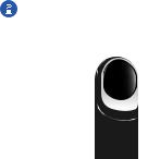
Hardware Overview
Microphone
Camera Lens
Light Sensor
LED
Swivel Base
Microphone Microphone for recording audio
Camera Lens Lens for viewing/recording video
Light Sensor Sensor for ambient light detection
LED Status indicator for the following:
LED State |
Status |
|
|
Alternating |
Device is busy; do not touch or unplug it. |
White/Blue |
This usually indicates that a process such |
|
as a firmware upgrade is taking place. |
|
|
Steady Blue |
Connected to UniFi Video Controller; |
|
Reset Button Pressed |
|
|
Flashing Green |
Disconnected from Controller |
|
|
Steady White |
Awaiting adoption |
|
|
Swivel Base Allows you to change the viewing angle of the camera by adjusting left or right. Useful if mounted on a wall or other permanent surface.
Bottom View
Ethernet Port |
|
|
|
|
Reset Button |
Ethernet Port The Ethernet Port is a 10/100 Mbps port used to supply power from a PoE 802.3af-compliant switch to the camera. The switch should be connected to a LAN running DHCP services and the UniFi Video Controller software.
Reset Button The Reset Button is used to reset the camera to factory defaults. Press and hold the Reset Button for more than 10 seconds while the camera is powered on.
Mounting Options
Use the Flush Mount by itself to install the G3 Flex camera on a desktop or tabletop. Out of the box, this mount comes preinstalled on the camera.
Use the Flush Mount with two screws to install the G3 Flex camera on a wall (vertically).
Use the Flush Mount with two screws to install the G3 Flex camera on a solid horizontal surface or ceiling.
Use the Pole Mount with two screws and the Outdoor Cover to install the G3 Flex camera on a wall or flat surface outdoors. The Outdoor Cover is not required for indoor installations.
Use the Pole Mount with two plastic zip ties and the Outdoor Cover to install the G3 Flex camera on an outdoor pole. The Outdoor Cover is not required for indoor pole installations.

Additional Mounts Available
There are two additional mounts available for the G3 Flex: a Ceiling Mount and a Pendant Mount. Each is sold separately.
Use the optional Ceiling Mount, Screw Kit, and
Mount Cover to install the G3 Flex camera on a solid horizontal surface or ceiling.
Use the optional Ceiling Mount, Mount Cover, and
Back Plate Assembly to install the G3 Flex camera on a drop tile ceiling or horizontal surface where the interior side of the Ceiling Mount is accessible.
Use the Pendant Mount to install the G3 Flex camera onto a fitted 3/4" or 1.5" conduit mount or ceiling pipe.
Optional Covers
There are also optional skin covers available to enhance the look of the G3 Flex camera and allow it to discreetly blend into the setting or environment it is installed in. Choose from one of the following design patterns: Black, Camouflage,
Concrete, Marble, and Wood.
Black |
Camoflauge |
Concrete |
Marble |
Wood |
Installation
The UVC G3 Flex can be installed using one of the following methods:
•Desktop For installing on a flat surface such as a desktop or table/shelf; could be set up for temporary installations.
•Wall/Ceiling For installing in a secure location; used more for stationary or permanent installations.
•Pole For installing on a pole (indoor or outdoor).
Proceed to the appropriate section for your installation.
Note: The viewing angle or surveillance coverage of the G3 Flex camera can be changed at any time.
•Tilt the lens up or down for vertical adjustment
•Turn the base left or right for horizontal adjustment
Desktop/Table
1. Remove the Flush Mount from the base of the camera.
2.Insert one end of the RJ-45 cable into the Ethernet Port and the other end into a PoE 802.3af-compliant switch.
3.Attach the camera to the Flush Mount by lining up the notches with the slots in the base of the camera. Press firmly together until the camera is secure.
Note: Ensure the Ethernet cable is seated in the notch between the Flush Mount and base of the camera.
 Loading...