


INSTALLATION MANUAL
MANUEL D’INSTALLATION
INSTALLATIONS-HANDBUCH
MANUALE D’INSTALLAZIONE
MANUAL DE INSTALACIÓN MANUAL DE INSTALAÇÃO INSTALLATIEHANDLEIDING
ЕГЧЕЙСЙДЙП ЕГКБФБУФБУЗУ
AIR CONDITIONER (SPLIT TYPE) CLIMATISEUR (TYPE SPLIT)
KLIMAGERÄT (SPLIT-SYSTEM)
CONDIZIONATORE D'ARIA (TIPO MULTIAMBIENTI)
APARATO DE AIRE ACONDICIONADO (TIPO SPLIT) AR CONDICIONADO (TIPO SPLIT)
AIRCONDITIONER (GESPLITST TYPE)
КЛЙМБФЙУФЙКП (ФХРПУ SPLIT)
<Under Ceiling Type> / <Type sous le plafond> <Zwischendeckentyp> / <Tipo sotto il soffitto>
<Modelo de techo> / <Tipo Sob o Tecto>
<Type voor montage boven verlaagd plafond> / <Фэрпт кЬфщ брь фзн пспцЮ>
Heat Pump Model/Modèle à thermopompe
Geräte mit Heizung/Modello con pompa di riscaldamento
Modelo con bomba de calor/Modelo de bomba térmica
Model met warmtepomp/МпнфЭлп ме БнфлЯб Иесмьфзфбт
Indoor Unit/Unité intérieure |
Outdoor Unit/Unité extérieure |
Raumeinheit/Unità interna |
Außengerät/Unità esterna |
Unidad interior/Unidade interior |
Unidad exterior/Unidade exterior |
Binnenunit/ЕущфесйкЮ mпнЬдб |
Buitenunit/ЕощфесйкЮ mпнЬдб |
RAV-SM561CT-E RAV-SM801CT-E RAV-SM1101CT-E RAV-SM1401CT-E
RAV-SM560AT-E, RAV-SM800AT-E, RAV-SM1100AT-E, RAV-SM1400AT-E,
SP560AT-E SP800AT-E SP1100AT-E SP1400AT-E
Please read this Installation Manual carefully before installing the Air Conditioner.
•This Manual describes the installation method of the indoor unit.
•For installation of the outdoor unit, follow the Installation Manual attached to the outdoor unit.
Veuillez lire attentivement ce Manuel d’installation avant d’installer le climatiseur.
•Ce manuel décrit la procédure d’installation de l’unité intérieure.
•Pour installer l’unité extérieure, reportez-vous au Manuel d’installation fourni avec l’unité extérieure.
Bitte lesen Sie dieses Handbuch sorgfältig, bevor Sie mit der Installation des Klimagerätes beginnen.
•In diesem Handbuch wird die Installation der Raumeinheit beschrieben.
•Um die Außeneinheit zu installieren, folgen Sie den Anweisungen in dem Handbuch, das der Außeneinheit beiliegt.
Prima di installare il condizionatore d’aria, leggere con attenzione questo manuale d’installazione.
•Questo manuale descrive il metodo d’installazione dell’unità interna.
•Per l’installazione dell’unità esterna, fare riferimento al manuale d’installazione fornito insieme all’unità esterna.
Lea atentamente este Manual de instalación antes de proceder a la instalación del aparato de aire acondicionado.
•Este manual describe el método de instalación de la unidad interior.
•Para la instalación de la unidad exterior, consulte el Manual de instalación que acompaña a la unidad exterior.
Leia atentamente o presente Manual de Instalação antes de instalar o Ar Condicionado.
•O presente manual descreve o método de instalar a unidade interior.
•Para a instalação de uma unidade exterior, siga o Manual de Instalação que acompanha a unidade exterior.
Lees deze installatiehandleiding zorgvuldig door voordat u de airconditioner gaat installeren.
•Deze installatiemethode beschrijft de installatiemethode van de binnenunit.
•Zie voor de installatie van de buitenunit, de installatiehandleiding bij de buitenunit.
Рбсбкблю дйбвЬуфе рспуечфйкЬ фп ЕгчейсЯдйп ЕгкбфЬуфбузт рсйн брь фзн егкбфЬуфбуз фпх Клймбфйуфйкпэ.
•Фп рбсьн ЕгчейсЯдйп ресйгсЬцей фз мЭипдп егкбфЬуфбузт фзт еущфесйкЮт мпнЬдбт.
•Гйб фзн егкбфЬуфбуз фзт еощфесйкЮт мпнЬдбт, бкплпхиЮуфе фп ЕгчейсЯдйп ЕгкбфЬуфбузт рпх ухнпдеэей фзн еощфесйкЮ мпнЬдб.

ADOPTION OF NEW REFRIGERANT
This Air Conditioner is a new type which adopts a new refrigerant HFC (R410A) instead of the conventional refrigerant R22 in order to prevent destruction of the ozone layer.
UTILISATION DU NOUVEAU REFRIGERANT
Ce climatiseur est d’un type inédit qui utilise le nouveau réfrigérant HFC (R410A) au lieu du réfrigérant traditionnel R22, afin d’éviter la destruction de la couche d’ozone.
EINFÜHRUNG EINES NEUEN KÜHLMITTELS
Dies ist ein neuartiges Klimagerät. Anstatt des herkömmlichen Kühlmittels R22 verwendet es das neue ozonschichtschonende HFC Kühlmittel R410A.
ADOZIONE DI UN NUOVO REFRIGERANTE
Questo condizionatore d'aria è di un tipo nuovo che adotta un nuovo refrigerate HFC (R410A) al posto del refrigerante convenzionale R22, per prevenire la distruzione dello strato di ozono dell'atmosfera terrestre.
ADOPCIÓN DE NUEVO REFRIGERANTE
Este aparato de aire acondicionado es un modelo reciente que incorpora el nuevo refrigerante HFC (R410A) en lugar del refrigerante convencional R22 para así evitar daños en la capa de ozono.
ADOPÇÃO DO NOVO REFRIGERANTE
Este ar condicionado é um modelo novo que adopta um novo refrigerante HFC (R410A) em vez do refrigerante convencional R22 para evitar a destruição da cama de ozono.
TOEPASSING VAN EEN NIEUW KOELMIDDEL
Deze airconditioner is een nieuwe type dat werkt met een nieuw koelmiddel HFC (R410A) in plaats van met het conventionele koelmiddel R22, als bijdrage om de aantasting van de ozonlaag te reduceren.
ХЙПИЕФЗУЗ НЕПХ ШХКФЙКПХ
Фп рбсьн Клймбфйуфйкь еЯнбй нЭпт фэрпт рпх хйпиефеЯ нЭп шхкфйкь HFC (R410A) уфз иЭуз фпх ухмвбфйкпэ шхкфйкпэ R22 рспкеймЭнпх нб впзиЮуей уфзн рспуфбуЯб фпх ьжпнфпт.

CONTENTS
Accessory parts and Parts to be procured locally ..................... |
1 |
6 |
TEST RUN ............................................................................ |
16 |
|
1 |
PRECAUTIONS FOR SAFETY ............................................. |
2 |
7 |
TROUBLESHOOTING ......................................................... |
17 |
2 |
SELECTION OF INSTALLATION PLACE ............................ |
4 |
8 |
Applicable Controls ........................................................... |
18 |
3 |
DRAIN PIPING WORK ........................................................... |
9 |
9 |
INSTALLATION/SERVICING TOOLS .................................. |
21 |
4 |
REFRIGERANT PIPING AND EVACUATING ..................... |
11 |
10 |
MAINTENANCE ................................................................... |
21 |
5 |
ELECTRICAL WORK ........................................................... |
13 |
|
|
|
|
SOMMAIRE |
|
|
||
Pièces accessoires et pièces non fournies ............................... |
23 |
6 |
ESSAI DE FONCTIONNEMENT ......................................... |
38 |
|
1 |
MESURES DE SECURITE .................................................. |
24 |
7 |
DEPANNAGE ....................................................................... |
39 |
2 |
SELECTION DU LIEU D’INSTALLATION .......................... |
26 |
8 |
COMMANDES UTILISABLES ............................................ |
40 |
3 |
INSTALLATION DES TUYAUX D’EVACUATION ................. |
31 |
9 |
OUTILS D’INSTALLATION/D’ENTRETIEN ........................ |
43 |
4 |
TUYAUTERIE DE FRIGORIGÈNE ET ÉVACUATION ......... |
33 |
10 |
ENTRETIEN ......................................................................... |
43 |
5 |
INSTALLATION ELECTRIQUE ........................................... |
35 |
|
|
|
|
|
|
|
|
|
|
|
INHALT |
|
|
|
Zubehör und bauseits bereitzustellende Teile .......................... |
45 |
6 |
TESTLAUF ........................................................................... |
60 |
|
1 |
SICHERHEITSVORKEHRUNGEN ...................................... |
46 |
7 |
FEHLERBESEITIGUNG ...................................................... |
61 |
2 |
AUSWAHL DES AUFSTELLUNGSORTES ........................ |
48 |
8 |
STEUERUNGSMÖGLICHKEITEN ...................................... |
62 |
3 |
INSTALLATION DES ABLAUFROHRS .............................. |
53 |
9 |
INSTALLATIONS/WARTUNGSWERKZEUGE ................... |
65 |
4 |
KÜHLMITTELLEITUNGSSYSTEM UND ENTLÜFTUNG .... |
55 |
10 |
WARTUNG ........................................................................... |
65 |
5 |
ELEKTROINSTALLATION .................................................. |
57 |
|
|
|
|
|
|
|
|
|
|
|
INDICE |
|
|
|
Accessori e parti da acquistare sul posto ................................. |
67 |
6 |
FUNZIONAMENTO DI PROVA ............................................ |
82 |
|
1 |
PRECAUZIONI PER LA SICUREZZA ................................ |
68 |
7 |
GUIDA PER I PROBLEMI DI FUNZIONAMENTO .............. |
83 |
2 |
SCELTA DEL POSTO D’INSTALLAZIONE ........................ |
70 |
8 |
COMANDI APPLICABILI .................................................... |
84 |
3 |
LAVORO PER TUBAZIONE DI SCARICO .......................... |
75 |
9 |
ATTREZZI PER INSTALLAZIONE/ |
|
4 |
TUBAZIONI DEL REFRIGERANTE E SCARICO............... |
77 |
10 |
ASSISTENZA TECNICA ...................................................... |
87 |
5 |
ESECUZIONE DEI COLLEGAMENTI ELETTRICI ............. |
79 |
MANUTENZIONE ................................................................ |
87 |
|
|
|
|
|
||
|
CONTENIDO |
|
|
||
Componentes accesorios y componentes de obtención local ... |
89 |
6 |
PRUEBA DE FUNCIONAMIENTO .................................... |
104 |
|
1 |
PRECAUCIONES PARA SU SEGURIDAD ......................... |
90 |
7 |
SOLUCIÓN DE PROBLEMAS .......................................... |
105 |
2 |
SELECCIÓN DEL LUGAR DE INSTALACIÓN ................... |
92 |
8 |
CONTROLES APLICABLES ............................................. |
106 |
3 |
TRABAJOS DE CANALIZACIÓN DE DESAGÜE .............. |
97 |
9 |
HERRAMIENTAS DE INSTALACIÓN Y REPARACIÓN ... |
109 |
4 |
TUBOS DE REFRIGERANTE Y EVACUACIÓN ................. |
99 |
10 |
MANTENIMIENTO ............................................................. |
109 |
5 |
TRABAJOS EN EL SISTEMA ELÉCTRICO ..................... |
101 |
|
|
|
|
|
|
|
|
|
|
|
ÍNDICE |
|
|
|
Acessórios e peças adquiridas localmente ............................ |
111 |
6 |
ENSAIO DE FUNCIONAMENTO ...................................... |
126 |
|
1 |
PRECAUÇÕES DE SEGURANÇA .................................... |
112 |
7 |
RESOLUÇÃO DE PROBLEMAS ...................................... |
127 |
2 |
SELECÇÃO DO LOCAL DE INSTALAÇÃO ..................... |
114 |
8 |
CONTROLOS APLICÁVEIS .............................................. |
128 |
3 |
INSTALAÇÃO DA TUBAGEM DE DRENAGEM ............... |
119 |
9 |
FERRAMENTAS DE INSTALAÇÃO/ASSISTÊNCIA ........ |
131 |
4 |
TUBAGEM DE REFRIGERANTE E EVACUAÇÃO ........... |
121 |
10 |
MANUTENÇÃO ................................................................. |
131 |
5 |
LIGAÇÕES ELÉCTRICAS ................................................ |
123 |
|
|
|
|
|
|
|
|
|
|
|
INHOUD |
|
|
|
Accessoires en niet meegeleverde onderdelen ...................... |
133 |
6 |
WERKINGSTEST .............................................................. |
148 |
|
1 |
VOORZORGSMAATREGELEN VOOR UW VEILIGHEID . 134 |
7 |
STORINGEN VERHELPEN ............................................... |
149 |
|
2 |
KEUZE VAN DE LOCATIE VOOR DE INSTALLATIE ....... |
136 |
8 |
BEDIENINGSELEMENTEN .............................................. |
150 |
3 |
AFVOERLEIDINGEN ......................................................... |
141 |
9 |
INSTALLATIE EN ONDERHOUDSGEREEDSCHAPPEN 153 |
|
4 |
KOELMIDDELLEIDINGEN EN ONTLUCHTEN ................ |
143 |
10 |
ONDERHOUD .................................................................... |
153 |
5 |
ELEKTRISCH GEDEELTE ................................................ |
145 |
|
|
|
|
|
|
|||
|
РЕСЙЕЧПМЕНБ |
|
|||
Рбселкьменб бнфбллбкфйкЬ кбй |
|
# ЗЛЕКФСПЛПГЙКБ ............................................................. |
167 |
||
ЕобсфЮмбфб брь фзн фпрйкЮ бгпсЬ .......................................... |
155 |
$ ДПКЙМЗ ЛЕЙФПХСГЙБУ .................................................... |
170 |
||
РСПЦХЛБОЕЙУ БУЦБЛЕЙБУ ............................................. |
156 |
% БНФЙМЕФЩРЙУЗ РСПВЛЗМБФЩН ................................... |
171 |
||
|
ЕРЙЛПГЗ ФПХ ЧЩСПХ ЕГКБФБУФБУЗУ ......................... |
158 |
& ЕЦБСМПУЙМПЙ ЕЛЕГЧПЙ ................................................ |
172 |
|
! ЕГКБФБУФБУЗ УЩЛЗНЩУЕЩН БРПУФСБГГЙУЗУ ......... |
163 |
' ЕСГБЛЕЙБ ЕГКБФБУФБУЗУ/ ЕРЙУКЕХЗУ ....................... |
175 |
||
" УЩЛЗНЩУЕЙУ ШХОЗУ КБЙ БРПУФСБГГЙУЗУ ................. |
165 |
УХНФЗСЗУЗ ...................................................................... |
175 |
||
ЕЛЛЗНЙКБ NEDERLANDS PORTUGUÊS ESPAÑOL ITALIANO DEUTSCH FRANCAIS ENGLISH

Accessory parts and Parts to be procured locally
r Accessory parts
Part name |
Q’ty |
Shape |
Usage |
|
|
|
|
Owner’s Manual |
1 |
— |
— |
|
|
|
|
Installation Manual |
1 |
This manual |
— |
|
|
|
|
Installation pattern |
1 |
— |
Drawing-out port of |
|
hanging bolt pipe |
||
|
|
|
|
|
|
|
|
Thermal insulation |
2 |
|
For thermal insulation of |
pipe |
|
pipe connecting section |
|
|
|
||
|
|
|
|
Washer |
4 |
M10 × Ø25 |
For holding down unit |
|
|
|
|
Hose band |
2 |
|
For connecting drain |
|
pipe |
||
|
|
|
|
|
|
|
|
<Separate sold parts>
Part name |
Q’ty |
Shape |
Usage |
Standard wired |
1 |
|
Model |
|
|
||
remote controller |
|
|
RBC-AMT21E |
Part name |
Q’ty |
Shape |
Usage |
Drain hose |
1 |
|
For connecting drain pipe |
Bushing |
1 |
|
For protection of edge at |
|
power taking-in port |
||
|
|
|
|
Thermal insulator |
1 |
|
For thermal insulation of drain |
|
hose (10t × 200 × 200) |
||
|
|
|
|
Thermal insulator |
1 |
|
For upper pipe hole of indoor |
of top plate |
|
unit (6t × 130 × 160) |
|
|
|
||
Banding band |
2 |
|
For prevention of open of |
|
drain hose thermal insulator |
||
|
|
|
r Parts to be procured locally
Connecting pipe (Liquid side)
(6.4mm (diam.), Nominal (diam.) 1/4” thick 0.8mm) RAV-SM561CT-E
(9.52mm (diam.), Nominal (diam.) 3/8” thick 0.8mm) RAV-SM801CT-E, RAV-SM1101CT-E, RAV-SM1401CT-E
Connecting pipe (Gas side)
(12.7mm (diam.), Nominal (diam.) 1/2” thick 0.8mm) RAV-SM561CT-E
(15.9mm (diam.), Nominal (diam.) 5/8” thick 1.0mm) RAV-SM801CT-E, RAV-SM1101CT-E, RAV-SM1401CT-E
Power supply cord
2.5mm² (H07RN-F or 245IEC66) (20m or less) 3.5mm² (AWG-12) (50m or less)
Connecting cable (indoor and outdoor cable) H07RN-F or 245IEC66 (1.5mm² or more)
Thermal insulation for refrigerant pipe
(10mm or more, thermal insulating foam polyethylene)
Thermal insulation for drain pipe (10mm or more, foam polyethylene)
Drain pipe (Outer 26mm (diam.)) (VP20)
Tapes
1

1 PRECAUTIONS FOR SAFETY
•Ensure that all Local, National and International regulations are satisfied.
•Read this “PRECAUTIONS FOR SAFETY” carefully before Installation.
•The precautions described below include the important items regarding safety. Observe them without fail.
•After the installation work, perform a trial operation to check for any problem.
Follow the Owner’s Manual to explain how to use and maintain the unit to the customer.
•Turn off the main power supply switch (or breaker) before the unit maintenance.
•Ask the customer to keep the Installation Manual together with the Owner’s Manual.
CAUTION New Refrigerant Air Conditioner Installation
•THIS AIR CONDITIONER ADOPTS THE NEW HFC REFRIGERANT (R410A) WHICH DOES NOT DESTROY OZONE LAYER.
The characteristics of R410A refrigerant are ; easy to absorb water, oxidizing membrane or oil, and its pressure is approx. 1.6 times higher than that of refrigerant R22. Accompanied with the new refrigerant, refrigerating oil has also been changed. Therefore, during installation work, be sure that water, dust, former refrigerant, or refrigerating oil does not enter the refrigerating cycle.
To prevent charging an incorrect refrigerant and refrigerating oil, the sizes of connecting sections of charging port of the main unit and installation tools are charged from those for the conventional refrigerant.
Accordingly the exclusive tools are required for the new refrigerant (R410A).
For connecting pipes, use new and clean piping designed for R410A, and please care so that water or dust does not enter. Moreover, do not use the existing piping because there are problems with pressure-resistance force and impurity in it.
ENGLISH
CAUTION To Disconnect the Appliance from Main Power Supply.
This appliance must be connected to the main power supply by means of a switch with a contact separation of at least 3 mm.
The installation fuse (25A D type  ) must be used for the power supply line of this conditioner.
 WARNINGS
•Ask an authorized dealer or qualified installation professional to install/maintain the air conditioner.
Inappropriate installation may result in water leakage, electric shock or fire.
•Turn off the main power supply switch or breaker before attempting any electrical work.
Make sure all power switches are off. Failure to do so may cause electric shock.
•Connect the connecting cable correctly.
If the connecting cable is connected in a wrong way, electric parts may be damaged.
•When moving the air conditioner for the installation into another place, be very careful not to enter any gaseous matter other than the specified refrigerant into the refrigeration cycle.
If air or any other gas is mixed in the refrigerant, the gas pressure in the refrigeration cycle becomes abnormally high and it resultingly causes pipe burst and injuries on persons.
•Do not modify this unit by removing any of the safety guards or by by-passing any of the safety interlock switches.
•Exposure of unit to water or other moisture before installation may cause a short-circuit of electrical parts.
Do not store it in a wet basement or expose to rain or water.
2

1 PRECAUTIONS FOR SAFETY
•After unpacking the unit, examine it carefully if there are possible damage.
•Do not install in a place that might increase the vibration of the unit.
•To avoid personal injury (with sharp edges), be careful when handling parts.
•Perform installation work properly according to the Installation Manual.
Inappropriate installation may result in water leakage, electric shock or fire.
•When the air conditioner is installed in a small room, provide appropriate measures to ensure that the concentration of refrigerant leakage occur in the room does not exceed the critical level.
•Install the air conditioner securely in a location where the base can sustain the weight adequately.
•Perform the specified installation work to guard against an earthquake.
If the air conditioner is not installed appropriately, accidents may occur due to the falling unit.
•If refrigerant gas has leaked during the installation work, ventilate the room immediately.
If the leaked refrigerant gas comes in contact with fire, noxious gas may generate.
•After the installation work, confirm that refrigerant gas does not leak.
If refrigerant gas leaks into the room and flows near a fire source, such as a cooking range, noxious gas might generate.
•Electrical work must be performed by a qualified electrician in accordance with the Installation Manual. Make sure the air conditioner uses an exclusive power supply.
An insufficient power supply capacity or inappropriate installation may cause fire.
•Use the specified cables for wiring connect the terminals securely fix. To prevent external forces applied to the terminals from affecting the terminals.
•Conform to the regulations of the local electric company when wiring the power supply.
Inappropriate grounding may cause electric shock.
•Do not install the air conditioner in a location subject to a risk of exposure to a combustible gas.
If a combustible gas leaks, and stays around the unit, a fire may occur.
3

2 SELECTION OF INSTALLATION PLACE
 WARNING
•Install the air conditioner at enough strong place to withstand the weight of the unit.
If the strength is not enough, the unit may fall down resulting in injury.
•Perform a specified installation work to guard against an earth quake.
An incomplete installation can cause accidents by the units failing and dropping.
•Install the air conditioner at a height 2.5m or more from the floor.
If you insert your hands or others directly into the unit while the air conditioner operates, it is dangerous because you may contact with revolving fan or active electricity.
 CAUTION
•Do not install the air conditioner in a location subject to a risk of exposure to a combustible gas.
If a combustible gas leaks and stays around the unit, a fire may occur.
Upon approval of the customer, install the air conditioner in a place that satisfies the following conditions.
•Place where the unit can be installed horizontally.
•Place where a sufficient servicing space can be ensured for safety maintenance and check.
•Place where drained water will not cause any problem.
Avoid installing in the following places.
•Place exposed to air with high salt content (seaside area), or place exposed to large quantities of sulfide gas (hot spring). (Should the unit be used in these places, special protective measures are needed.)
•Place exposed to oil, vapor, oil smoke or corrosive gas.
•Place where organic solvent is used nearby.
•Place close to a machine generating high frequency.
•Place where the discharged air blows directly into the window of the neighboring house. (For outdoor unit)
•Place where noise of the outdoor unit is easily transmitted.
(When installing the air conditioner on the boundary with the neighbor, pay due attention to the level of noise.)
•Place with poor ventilation. (Before air ducting work, check whether value of air volume, static pressure and duct resistance are correct.)
Installation space
Secure the specified space in the figure for installation and servicing.
250 or more |
or500more |
250 or more |
4
2 SELECTION OF INSTALLATION PLACE
Height of ceiling
Set the installable height of the ceiling within 4m, otherwise the air distribution will become poor.
If height of ceiling exceeds 3.5m, hot air becomes difficult to reach the floor surface, and then the change of setup of high ceiling is necessary.
When incorporating a filter sold separately, the change of setup of high ceiling is also necessary.
For the change method of high ceiling, refer to the application control, “In case of installation to high ceiling” and “In case of incorporating filter sold separately” in this Manual.
List of installable ceiling height
Setup data |
|
|
|
|
|
0000 |
Standard (At shipment) |
3.5m or less |
|
|
|
0001 |
High ceiling 1 |
4.0m or less |
|
|
|
According to the conditions of installation, setup time of turning-on of filter sign (notification of filter cleaning) of the remote controller can be changed.
When it is difficult to warm up the room due to installation place or structure of the room, the detection temperature of heating can be raised.
For change the setup time, refer to the application control, “Change of filter sign turning-on time” and “How to increase the heating effect” in this Manual.
In case of wireless type
Decide the position which remote controller is operated and the installation place.
And then refer to the Installation Manual of the wireless remote controller kit sold separately.
(The signal of the wireless type remote controller can be received within approx. 8m. This distance is a criterion and varies a little according to capacity of the battery, etc.)
•To prevent malfunction, select a place where is not affected by a fluorescent lamp or direct sunlight.
•Two or more (up to 6 units) wireless-type indoor units can be set in a room.
Approx .  8m
8m
Before installation
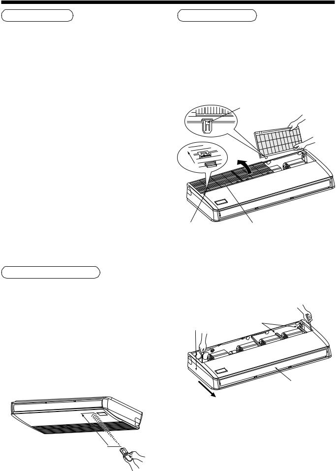
1.Removal of suction grille
Slide the suction grille fixing knobs (two positions) toward the arrow direction, and then open the suction grille.
Under the condition of suction grille opened, push the hook section of hinges (two positions) at the rear side, and then pull out the suction grille.
Pull out suction grille while pushing hook.
 Hinge
Hinge
Slide
Suction grille |
Suction grille |
fixing knob |
|
2.Removal of side panel
After removing the side panel fixing screws (1 each at right and left), slide the side panel forward and then remove it.
Protector
Side panel
Level flap
Slide forward.
3.Removal of protective vinyl
Peel out the protective vinyl on the level flap.
4.Removal of protector
Remove the protectors (2 pcs.) of the fan.
(RAV-SM801CT only)
5

External view
REQUIREMENT
Strictly comply with the following rules to prevent damage of the indoor units and human injury.
•Do not put a heavy article on the indoor unit. (Even units are packaged)
•Carry in the indoor unit as it is packaged if possible. If carrying in the indoor unit unpacked by necessity, be sure to use buffering cloth, etc. to not damage the unit.
•Do not apply force to the other parts (refrigerant pipe, drain pan, foamed parts, or resin parts, etc.).
•Carry the package by two or more persons, and do not bundle it with PP band at positions other than specified.
|
|
|
Upper pipe draw-out port (Knockout hole) |
|
|
128 |
Power supply cable take-in port (Knockout) |
216 |
|
|
Remote controller cable takein port |
|||
|
84 |
(Knockout hole) |
|
110 76 |
320 170 |
position) |
53 |
70 |
|
|
(Hanging |
Left drain size |
Refrigerant pipe |
|
|
(Liquid side ØC) |
|
||
|
|
|
||
|
|
B (Hanging position) |
|
|
|
|
Refrigerant pipe (Gas side ØD) |
75 |
|
|
|
|
|
146 |
Hanging bolt |
|
|
||
|
Within 50 |
Ceiling surface |
|
|
|
Unit |
|
|
|
|
|
|
|
|
A
|
210 |
Pipe draw-out port (Knockout hole) |
|
|
||
|
167 |
|
|
|
||
|
|
Drain port VP20 |
|
|
||
|
|
|
|
|
||
50 |
105 |
|
(Inner dia. Ø26, hose attached) |
|
|
|
|
|
|
|
|
|
|
130 |
|
|
114 |
|
|
|
|
|
|
41 |
|
|
|
|
680 |
(Liquid pipe) |
(Gas pipe) |
|
|
|
|
|
200 |
216 |
|
|
|
Drain pipe connecting port |
|
|
|
|||
97 |
|
|
|
|
|
|
|
|
|
Remote controller cable takein port |
|
|
|
|
|
347 |
Power supply cable take-in port (Knockout hole) |
|||
|
262 |
|
Remote controller cable takein port |
|||
|
|
90 |
32 |
(Knockout hole) |
|
32 |
|
135 |
92 |
84 |
|||
|
145 |
|
|
|
|
171 |
|
|
Outside air take-in port |
|
|
||
|
|
(Duct sold separately)(Knockout hole Ø92) |
|
|
||
Pipe hole on wall (Ø100 hole) Drain left pipe draw-out port (Knockout hole)
Wireless sensor |
Model name |
A |
B |
C |
D |
|
561CT |
910 |
855 |
Ø6.4 |
Ø12.7 |
||
mounting section |
||||||
|
801CT |
1180 |
1125 |
Ø9.5 |
Ø15.9 |
|
|
1101CT to 1401CT |
1595 |
1540 |
|||
|
|
|
Considering pipe/wire connecting work inside the ceiling after the indoor unit has been hanged, select an installation place and determine piping direction.
•If the ceiling has already been set before hanging the main unit, prepare refrigerant pipe, drain pipe, indoor connecting wire, remote controller cord, etc. up to the place where pipe and wire can be connected.
•Check the size of the indoor unit, and match the indoor unit size using the attached installation pattern.
How to use attached installation pattern
Using the pattern, positioning of the hanging bolt and pipe hole can be performed.
*As an error to some degree may generate on the pattern size due to temperature and humidity, be sure to confirm the size.
Installation pattern
Ceiling surface
Wall face
6

2 SELECTION OF INSTALLATION PLACE
Installation of hanging bolts
Use M10 hanging bolts (4 pcs, to be local procure). Matching to the existing structure, set pitch according to size in the unit external view as shown below.
New concrete slab
Install the bolts with insert brackets or anchor bolts.
|
|
Rubber |
|
|
Anchor bolt |
(Blade type |
(Slide type |
(Pipe hanging |
bracket) |
bracket) |
anchor bolt) |
Steel flame structure
Use existing angles or install new support angles.
 Hanging bolt
Hanging bolt |
Support angle |
Existing concrete slab
Use a hole-in anchors, hole-in plugs, or a hole-in bolts.
Pipe knockout hole
•In case of taking pipe from the rear side
*Cut off the groove section with a plastic cutter, etc.
 Rear cover
100
Opened when refrigerant pipe is taken out from the rear side
Grooves
Opened when only drain pipe is taken out from the rear side
•In case of taking pipe from right side
*Cut off the groove section with a metal saw or plastic cutter, etc.
Groove
Side panel (Right)
•In case of taking pipe from left side
Taking pipe from left side is applied only to the drain pipe.
The refrigerant pipe cannot be taken out from the left side.
*Cut off the groove section with a metal saw or plastic cutter, etc.
Draw-out direction of pipe/cable
•Decide installation place of the unit and draw-out direction of pipe and cable.
Knockout hole of power cable take-in port
Open the power cable take-in port (Knockout hole) shown in the external view and then mount the attached bushing.
Groove |
Side panel (Left side)) |
•In case of taking pipe from upper side
Taking pipe from upper side is applied only to the refrigerant pipe.
When taking out the drain pipe from the upper side, use a drain up kit sold separately.
Open the upper pipe draw-out port (Knockout hole) shown in the external view.
(Knockout hole of thin plate)
After piping, cut off the attached thermal insulator of the top plate to pipe shape, and then seal the knockout hole.
7
Installation of indoor unit
•Preparation before holding down main unit
*Confirm the presence of the ceiling material beforehand because the fixing method of hanging metal when the ceiling material is set differs from that when the ceiling material is not set.
<There is ceiling material>
Hanging bolt
 (Procured locally)

 Ceiling surface
Indoor
unit
Washer (Accessory)
Double nut
(Procured locally)
Hanging metal
Nut |
Hanging bolt |
|
(Procured locally) |
||
(Procured locally) |
||
|
||
|
Ceiling surface |
Indoor
unit
Washer (Accessory)
Double nut
(Procured locally)
Hanging metal
*Tighten the hanging metal with upper/lower nuts as shown in the figure.
<There is no ceiling material>
Hanging bolt  (Procured locally)
Washer
 (Procured locally) Indoor

unit
Washer (Accessory)
Double nut (Procured locally)
• Holding down of main unit
1) Attach washer and nuts to the hanging bolt.
Ceiling surface |
30 |
||
20 to |
|||
|
|
||
Washer |
Double nut |
||
(Accessory) |
(Procured locally) |
||
Hanging bolt
2)Hang the unit to the hanging bolt as shown the figure below.
3)As shown in the figure below, fix the ceiling material securely with the double nuts.
REQUIREMENT
•The ceiling surface may not be horizontal. Be sure to confirm that width and depth directions are level.
Installation of remote controller (Sold separately)
For installation of the wired remote controller, follow the Installation Manual attached with the remote controller.
•Pull out the remote controller cord together with the refrigerant pipe or drain pipe.
Be sure to pass the remote controller cord through upper side of the refrigerant pipe and drain pipe.
•Do not leave the remote controller at a place exposed to the direct sunlight and near a stove.
•Operate the remote controller, confirm that the indoor unit receives a signal surely, and then install it. (Wireless type)
•Keep 1m or more from the devices such as television, stereo, etc.
(Disturbance of image or noise may generate.) (Wireless type)
8
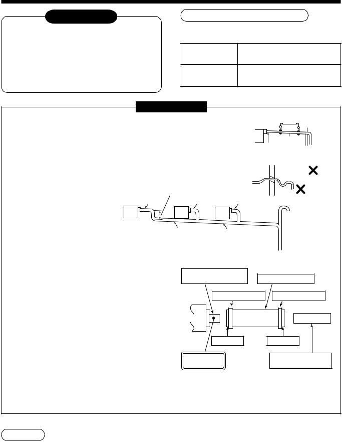
3 DRAIN PIPING WORK
 CAUTION
•Following the Installation Manual, perform the drain piping work so that water is properly drained, and apply a heat insulation so as not to cause a dew. Inappropriate piping work may result in water leakage in the room and wet of furniture.
Piping/Heat insulating material
Require the following materials for piping and heat insulating at site.
Piping
Hard vinyl chloride pipe VP20 (Outer dia. : Ø26mm)
Heat insulator
Foam polyethylene :
Thickness 10mm or more
REQUIREMENT
• |
Be sure to perform heat insulation of the drain pipes of the indoor unit. |
1.5m to 2m |
Support |
• |
Never forget to perform heat insulation of the connecting part with the indoor |
|
bracket |
|
|
||
|
unit. An incomplete heat insulation causes dewing. |
|
|
•Set the drain pipe with downward slope (1/100 or more), and do not make swelling or trap on the piping. It may cause an abnormal sound.
•For length of the traversing drain pipe, restrict to 20m or less. In case of a long pipe, provide support brackets with interval of 1.5 to 2m in order to prevent waving.
As long as possible (10cm)
VP25 |
VP25 |
Heat |
1/100 or more |
insulator |
downward |
Arched shape
Trap
VP25
Extended ventilating pipe
•Set the collective piping as shown in the right figure.
•Be sure not to apply force to the connecting part of the drain pipe.
•The hard vinyl-chloride pipe cannot be directly connected to the drain pipe connecting port of the indoor unit.
For connection with the drain pipe connecting port, be sure to use/fix the attached flexible hose with the hose band, otherwise a damage or water leak is caused on the drain pipe connecting port.
VP30 or more |
Downward slope |
|
|
|
1/100 or more |
|
|
<Collective piping> |
|
|
|
Drain pipe connecting port |
|
|
|
|
(Hard socket) |
Attached flexible hose |
|
|
Attached hose band |
Attached hose band |
|
Drain pan |
|
|
|
|
Soft socket |
|
Soft socket |
Adhesive agent |
|
VP20 vinyl chloride pipe |
|
prohibited |
|
(procured locally) |
|
Adhesive inhibited :
Use the attached flexible hose and hose band for connecting the drain hose to the clear drain socket.
If applying the adhesive, socket will be damaged and cause water leakage.
Drain up
When not securing down slope on the drain pipe, use a drain up kit sold separately.
Also refer to the “Drain up kit installation manual”.
The drain pipe can be raised 60cm from the top face of the main unit.
* When using drain up kit, both drain pipe and refrigerant pipe can be taken only from upper side.
9

Connection of drain hose
•Insert the attached drain hose into the drain pipe connecting port on the drain pan up to the end.
•Fit the attached hose band to the end of the pipe connecting port, and then tighten it securely.
REQUIREMENT
•Be sure to fix the drain hose with the attached hose band, and set the tightening position upward.
•As the draining is the natural water draining, arrange the pipe outside of the unit on the down slope.
•If piping is performed as shown in the figure, drain cannot be discharged.
Refrigerant pipe
Drain pipe
Drain pipe
Thermal insulating process
•Using the attached drain hose thermal insulator, lap the connecting section and the drain hose without clearance, and then tighten with two handing band so that thermal insulator does not open.
•Covering the attached drain hose thermal insulator, lap the thermal insulator (procured locally) to the drain pipe without clearance.
Lap covering connecting section
between drain pan and drain hose. Thermal insulator (procured locally)
Drain hose
Drain |
pan |
Hose band Banding band Hose band
Attached thermal insulator
*Tighten the banding band so that attached thermal insulator is not pushed excessively.
Lap the attached thermal insulation so that the one end is put on the other end at the upper side.
Fit the attached hose band to the end of the hose, lay down the knob, and then tighten hose band.
Drain pan
Attached drain hose
Confirm that soft hose is pushed in up to the end of the drain pan.
Connection of drain pipe
•Connect the hard vinyl chloride pipe (procured locally) to the mounted drain hose which was attached.
•In case of taking pipe from the left side
•In case of taking pipe from the left side, exchange the plug from left to right. Push in the plug of which end is not sharp up to the end.
Drain pan
Pulg
10

4 REFRIGERANT PIPING AND EVACUATING
Refrigerant Piping
•The connecting sections of the refrigerant pipes are provided at the positions in the figure below.
Upper side |
Rear side |
* When using the drain up kit sold |
|
separately, the pipe can be drawn |
|
|
|
|
Right |
|
out only from the upper side. |
• Flaring diam. meter size : A (Unit : mm)
|
|
A +0 |
|
Outer diam. of copper pipe |
|
- 0.4 |
|
R410A |
|
R22 |
|
|
|
||
|
|
|
|
6.4 |
9.1 |
|
9.0 |
|
|
|
|
9.5 |
13.2 |
|
13.0 |
|
|
|
|
12.7 |
16.6 |
|
16.2 |
|
|
|
|
15.9 |
19.7 |
|
19.2 |
|
|
|
|
1.Use copper pipe with 0.8 mm or more thickness.
(In case pipe size is Ø15.9, with 1.0mm or more.)
2.Flare nut and flare works are also different from those of the conventional refrigerant.
Take out the flare nut attached to the main unit of the air conditioner, and use it.
CAUTION
IMPORTANT 4 POINTS FOR PIPING WORK
1.Remove dust and moisture from the inside of the connecting pipes.
2.Tight connection (between pipes and unit)
3.Evacuate the air in the connecting pipes using VACUUM PUMP.
4.Check the gas leakage. (Connected points)
Permissible Piping Length and Heat
They vary according to the outdoor unit. For details, refer to the Installation Manual attached to the outdoor unit.
Flaring
Insert a flare nut into the pipe, and flare the pipe.
As the flaring sizes of R410A differ from those of refrigerant R22, the flare tools newly manufactured for R410A are recommended.
However, the conventional tools  B can be used by adjusting
projection margin of the copper pipe.
• Projection margin in flaring : B (Unit : mm)
Rigid (Clutch type)
Outer diam. of |
R410A tool used |
Conventional tool used |
|||
|
|
|
|
||
copper pipe |
|
R410A |
R22 |
R410A |
R22 |
|
|
||||
|
|
|
|
|
|
6.4 to 15.9 |
0 to 0.5 |
(Same as left) |
1.0 to 1.5 |
0.5 to 1.0 |
|
|
|
|
|
|
|
Imperial (Wing nut type)
Outer diam. of copper pipe |
R410A |
R22 |
|
|
|
6.4 or 9.5 |
1.5 to 2.0 |
1.0 to 1.5 |
|
|
|
12.7 or 15.9 |
2.0 to 2.5 |
1.5 to 2.0 |
|
|
|
* In case of flaring for R410A with the conventional
flare tool, pull it out approx. |
A |
|||
0.5 mm more than that for R22 to |
|
|
|
|
|
|
|
||
adjust to the specified flare size. |
|
|
|
|
|
|
|
||
The copper pipe gauge is useful |
|
|
|
|
for adjusting projection margin size. |
|
|
|
|
Tightening connection
CAUTION
•Do not apply excessive torque. Otherwise, the nut may crack depending on the conditions.
|
(Unit : N•m) |
|
|
Outer diam. of copper pipe |
Tightening torque |
|
|
6.4 mm (diam.) |
14 to 18 (1.4 to 1.8 kgf•m) |
|
|
9.5 mm (diam.) |
33 to 42 (3.3 to 4.2 kgf•m) |
|
|
12.7 mm (diam.) |
50 to 62 (5.0 to 6.2 kgf•m) |
|
|
15.9 mm (diam.) |
68 to 82 (6.8 to 8.2 kgf•m) |
|
|
• Tightening torque of flare pipe connections
Pressure of R410A is higher than that of R22. (Approx. 1.6 times) Therefore, using a torque wrench, tighten the flare pipe connecting sections which connect the indoor
and outdoor units of the specified tightening torque.
Incorrect connections may cause not only a gas
leak, but also a trouble of the refrigeration cycle.
Flare at  outdoor unit side
Align the centers of the connecting pipes and tighten the flare nut as far as possible with your fingers. Then tighten the nut with a spanner and torque wrench as shown in the figure.
Half union 

 Flare nut
Externally |
Internally |
threaded side |
threaded side |
Use a wrench to secure. |
Use a torque wrench to tighten. |
11
Piping with outdoor unit
•Shape of valve differs according to the outdoor unit.
For details of installation, refer to the Installation Manual of the outdoor unit.
Open the valve fully
Open the valve of the outdoor unit fully. A 4mmhexagonal wrench is required for opening the valve.
For details, refer to the Installation Manual attached to the outdoor unit.
Air purge
Using a vacuum pump, perform vacuuming from the charge port of valve of the outdoor unit.
For details, follow to the Installation Manual attached to the outdoor unit.
•Never use the refrigerant sealed in the outdoor unit for air purge.
REQUIREMENT
For the tools such as charge hose, etc., use those manufactured exclusively for R410A.
Refrigerant amount to be added
For addition of the refrigerant, add refrigerant “R410A” referring to the attached Installation Manual of outdoor unit.
Be sure to use a scale to charge the refrigerant of specified amount.
Gas leak check
Check with a leak detector or soap water whether gas leaks or not, from the pipe connecting section or cap of the valve.
REQUIREMENT
Use a leak detector manufactured exclusively for HFC refrigerant (R410A, R134a, etc.).
Thermal insulation process
Apply thermal insulation for the pipes separately at liquid side and gas side.
For the thermal insulation to the pipes at gas side, be sure to use the material with heat-resisting temperature 120°C or higher.
Using the attached thermal insulation material, apply the thermal insulation to the pipe connecting section of the indoor unit securely without gap.
REQUIREMENT
•Charging an excessive or too little amount of refrigerant causes a trouble of the compressor. Be sure to charge the refrigerant of specified amount.
•A personnel who charged the refrigerant should write down the pipe length and the added refrigerant amount in the nameplate attached to the service panel of the outdoor unit. It is necessary to troubleshoot the compressor and refrigeration cycle malfunction.
REQUIREMENT
Apply the thermal insulation to the pipe connecting section of the indoor unit securely up to the root without exposure of the pipe. (The pipe exposed to the outside causes water leak.)
12
 Loading...