


VS 530C
GB
1
Wireless video transmitter
Precautions
• Safety
This equipment contains heat sensitive components. Maximum ambient
temperature must not exceed 35° Celsius.
Humidity in rooms where this equipment is situated must not exceed a
hygrometric level of 85 %. If you have to use your equipment outside, avoid
exposing it to rain water or to splashes. The transition from a cold
environment to a hot one may cause condensation. Allow it to dry by itself
before re-starting the equipment.
In the event of prolonged absence, switch off the equipment by means of the
on/off switch. Even when switched off, certain components remain live. In order
to insulate it completely you must remove the plug from the main electricity
supply.
In the event of an electrical storm, it is advisable to disconnect the equipment
from the electricity supply so as to avoid potentially damaging electrical or
electromagnetic surges. To this end, make sure that the mains plug is easily
accessible for disconnection.
Disconnect the equipment immediately if you detect a smell of burning or
smoke. Under no circumstances must you open the equipment yourself;you run
the risk of electrocution.
• Maintenance
Clean the equipment with a soft cloth and a neutral detergent. The use of
solvents, abrasive products or alcohol-based products is likely to damage the
equipment.
• Regulations
This equipment must only be installed inside. Its use is restricted to private radio
transmission. Connection to a public or independent network, or to an outside
aerial is prohibited.
Under no circumstances should this appliance be put to industrial use. It is
designed solely for domestic operation.
THOMSON multimedia disclaims all responsibility in the event of use
that does not comply with the present instructions.
VS530C 24/10/00 9:56 Page 1

2
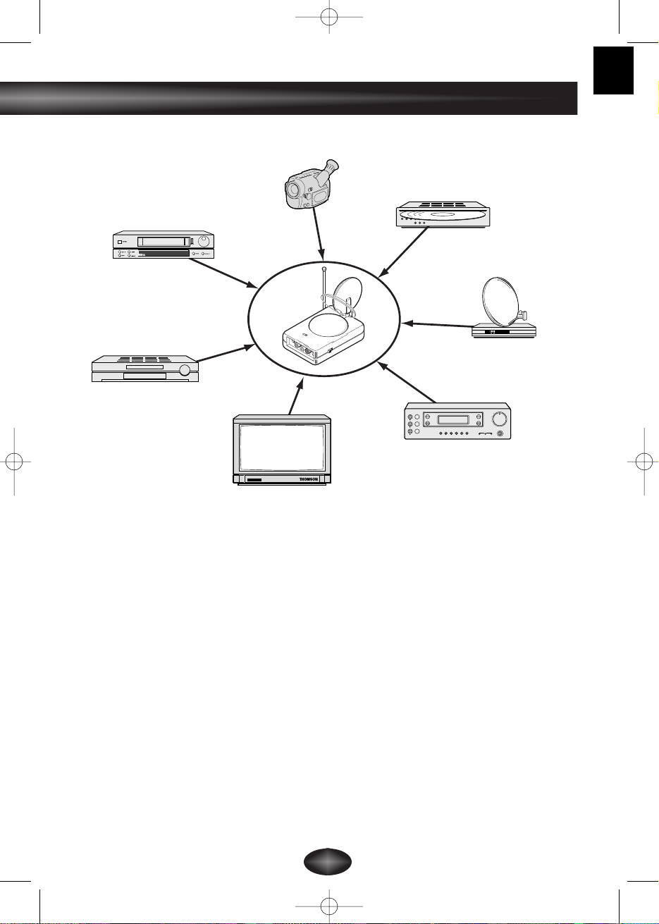
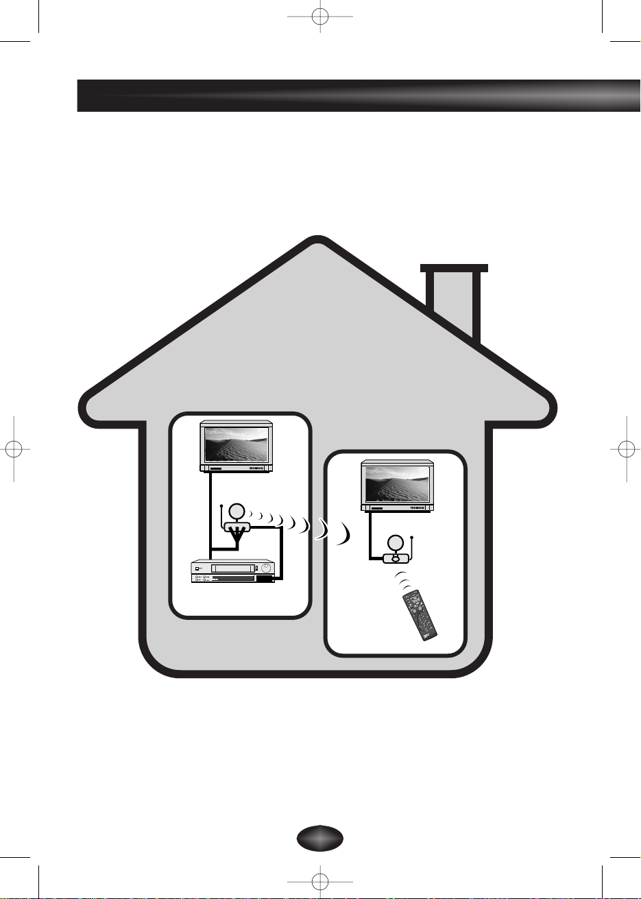
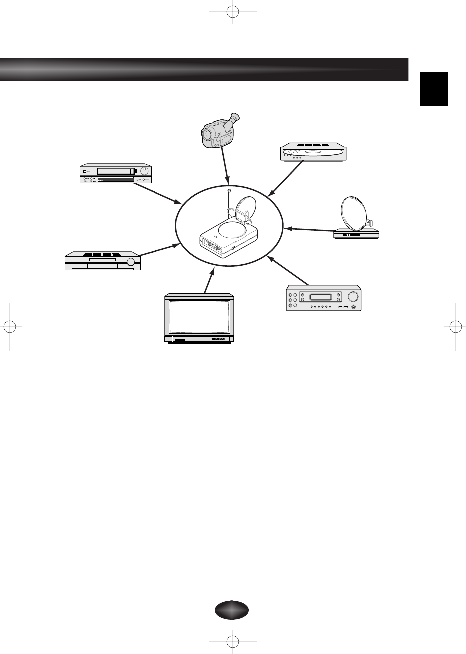
Principles of operation
LIVING ROOM
BEDROOM
Transmitter
Video recorder, satellite receiver,...
Receiver
Remote control for video
recorder, satellite
receiver,…or universal
remote control.
VS530C 24/10/00 9:56 Page 2
GB
3
off
on
VIDEO IN
REMOTE
OUT
AUDIO IN
DC
DVD player
Television set
Video recorder
Camcorder
Video disc player
Satellite/Cable receiver
and decoder
A/V Amplifier
The Video Sender VS 530 C,VS 530 CU, VS 530 CE or VS 530 CF permits
the relay of an Audio-Video signal from your main set-up to a second television
set located in another room and equipped with a scart connection.The main set-
up is the place in which you have chosen to install the majority of your equipment
(television set, video recorder, satellite receiver, DVD player,..) you can operate
the units from the room with the second television set by using their remote
controls, or with a universal remote control.
You can also use the Video Sender to keep an eye on your baby by connecting
the transmitter to a camcorder pointing in the direction of the baby’s bed, and the
receiver to a television set or monitor placed next to you. A scart / cinch adapter
or cinch / cinch cable is needed for the camcorder connection (depending on type
of equipment), not supplied.
It is possible to relay music if you connect the transmitter to an amplifier (AUDIO
OUT) and the receiver to a second amplifier (AUDIO IN) in another room. In this
case, you will need to purchase 1 cinch-to-cinch cable, which is not supplied.
VS530C 24/10/00 9:56 Page 3
4
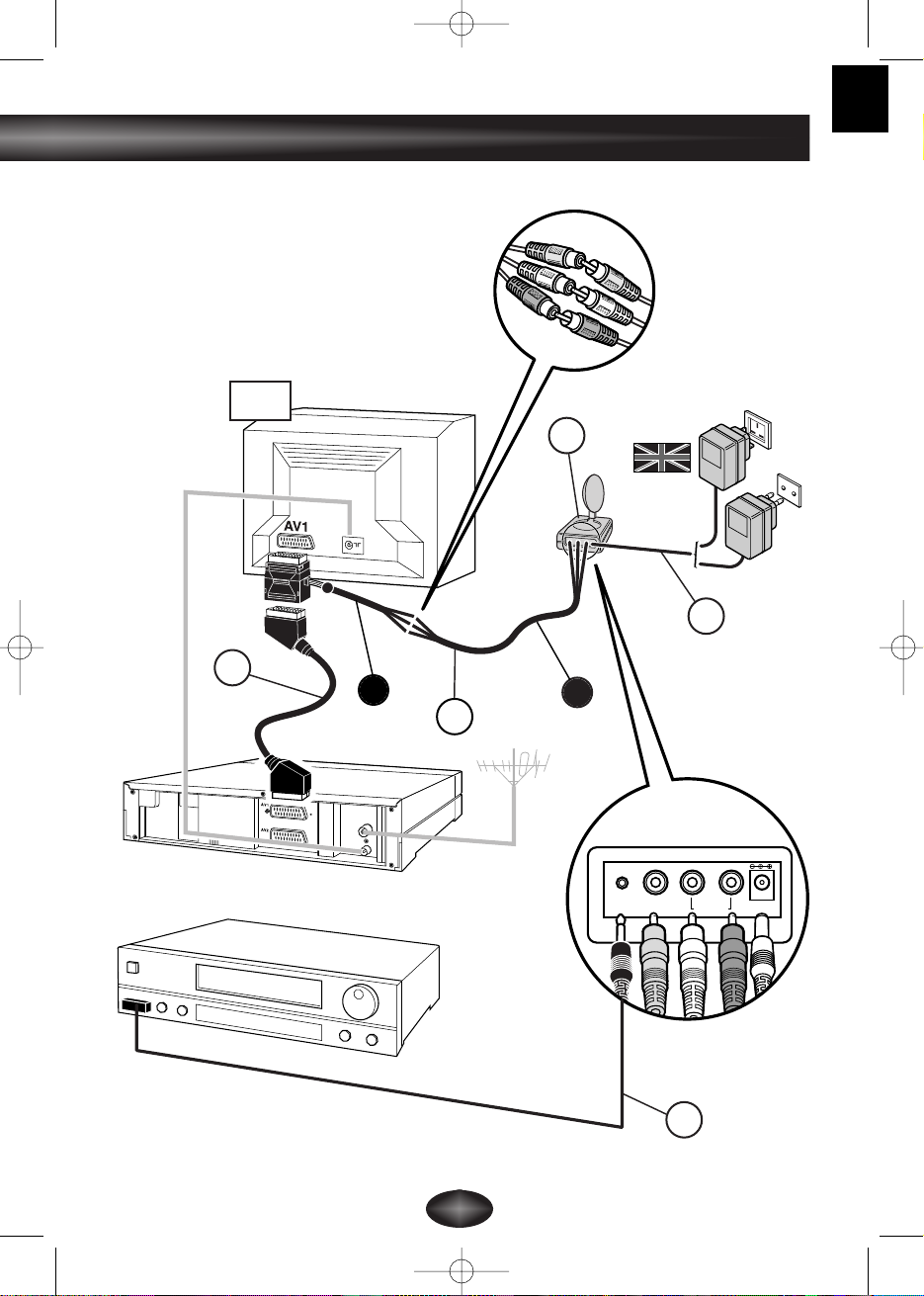
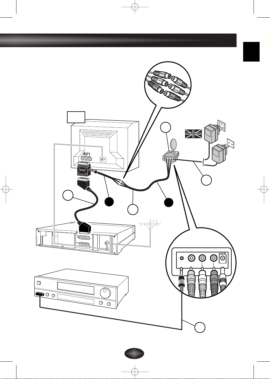
Installation of transmitter
Unfold the cover of this instruction manual in order to view the components
of the Video Sender and refer to the connection scheme on page 5.
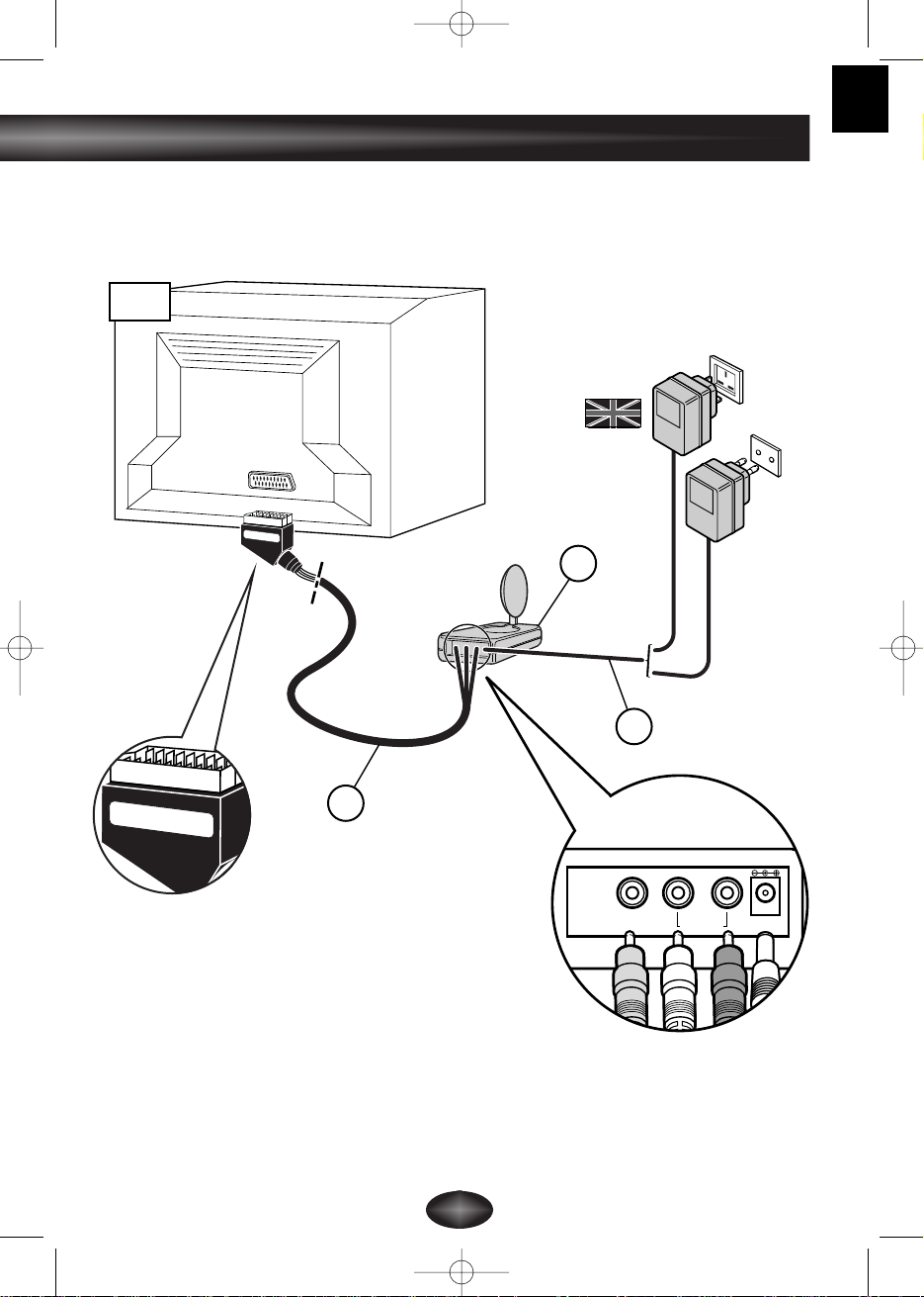
1. Place the transmitter (1) on, or near, the unit whose sound and pictures you
wish to relay and connect it using the cable (2 A and B),respecting the colours
of the 3 cinch connectors (red and white for audio, yellow for video). Plug the
SCART connector into one of the television's output sockets (preferably AV1).
Purchase a SCART cable (not supplied) and connect the unit whose pictures
and sound you wish to relay to the adapter 2B already plugged into the
television (see item
*
on, page 5).
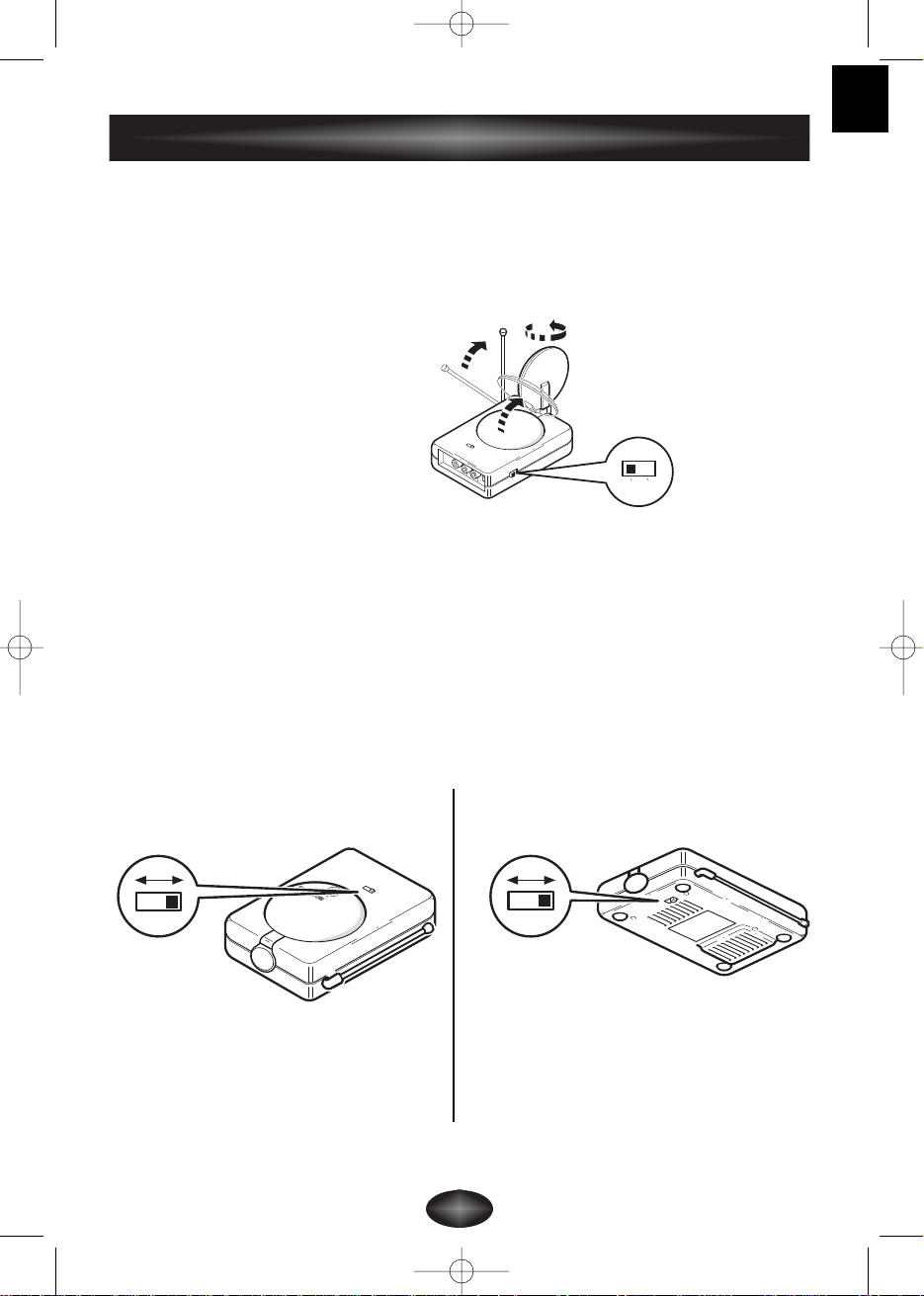
2. Set up the parabolic aerial of the sender (1) and point it in the direction of the
room containing the second television set (TV2).
3. Raise and extend the telescopic aerial of the sender (1).
4. Fit the lead (4) following these stages:
- connect the jack plug to the
REMOTE OUT socket.
- unwind the lead and place one cell near the infrared window of the unit to be
operated (video recorder or other).
- ask somebody else to go to the room containing the second television set
(TV2) and use the remote control of the unit to be operated.
- by moving the cell around in front of the unit to be operated you will find the
location that permits its control from the other room.You must fix the cell in
that position. Usually,this will be a more or less large, transparent area located
on the front of the unit.
5. Remove the protective paper from the adhesive surface of the lead's infrared
cells (4), stick them on the infrared windows of the units to be operated and
connect the jack plug to the appropriate socket (REMOTE OUT) on the
transmitter (1). The lead is fitted with 3 cells enabling you to relay pictures and
sound from 3 different units connected to the television set (TV1).
6. Fit the mains supply lead (3) to the transmitter and plug it into a
220/240 V ~ 50 Hz mains power supply.
VS530C 24/10/00 9:56 Page 4
GB
5
AUDIO IN DC 12VVIDEO IN
REMOTE
OUT
2
1
3
4
220/240V
~ 50 Hz
TV1
*
A
B
VS530C 24/10/00 9:56 Page 5

6
Unfold the cover of this instruction manual in order to view the components
of the Video Sender and refer to the connection scheme on page 7.
1. Place the receiver (5) on, or near, the second television set.
2. Connect the receiver (5) to the second television set using the lead (6)
following the same instructions as for the transmitter.
3. Set up the parabolic aerial of the receiver (5) and point it in the direction of
the main television set (TV1).
4. Raise and extend the telescopic aerial of the receiver (5).
5. Fit the mains supply lead (7) to the receiver and plug it into a
220/240 V ~ 50 Hz mains power supply.
! THE PARABOLIC AERIAL permits the relay of Audio-Video signals to a
maximum range of 30 meters when not hindered by any object. Inside a house
this range is reduced and will depend on the types of material encountered by the
waves.
! THE TELESCOPIC AERIAL permits the control of the unit whose pictures you
wish to see in the room containing the second television set (TV2).
! THE POWER SUPPLY plug fitted to the transmitter (1) is not the same as the
one fitted to the receiver (7).
Installation of receiver
VS530C 24/10/00 9:56 Page 6
GB
7
Receiver
Receiver
AUDIO OUT DC 12VVIDEO OUT
220/240V ~ 50 Hz
6
TV2
5
7
VS530C 24/10/00 9:56 Page 7
8
Instructions for use
1. Switch on the transmitter (1) and the receiver (5) by switching their on/off
buttons to the on position.
2. Make sure that the transmitter and the receiver are set to the same channel by
checking the position of the selectors located under the casing.They must be
set to the same channel (same letter).
3. Switch on your equipment (television sets, video recorders ...) in both rooms.
4. Using the remote control of the unit whose pictures you wish to see, and from
the room containing the second television set (TV2), select the channels or
video functions (or others) according to the unit you are controlling.
Special operating details:
No pictur
e on TV2? If you fail to obtain the desired picture on the second
television set TV2, select the AV socket, to which the receiver (5) is
connected, using the television's remote control.
Canal + on TV2? In order to be visible on the second television set (TV2),
the picture coming from a decoder must pass through a video recorder
that is switched on, either in AV2 mode, or on the channel no. set aside for
Canal +. (Refer to the instruction manuals of the units concerned).
Use of a monitor? If your second television set does not have a connection
for an outside aerial (terrestrial reception), or if it is a monitor, you will be
able to see the channels in the room containing the second television set
by selecting those of the video recorder with its remote control.
The picture is scrambled? The running of certain equipment (micro-wave
ovens, digital telephone DECT, un-shielded acoustic loudspeakers, etc ...)
may interfere with signal transmission. Ensure that they are kept away
from the transmitter and the receiver or switch them off.
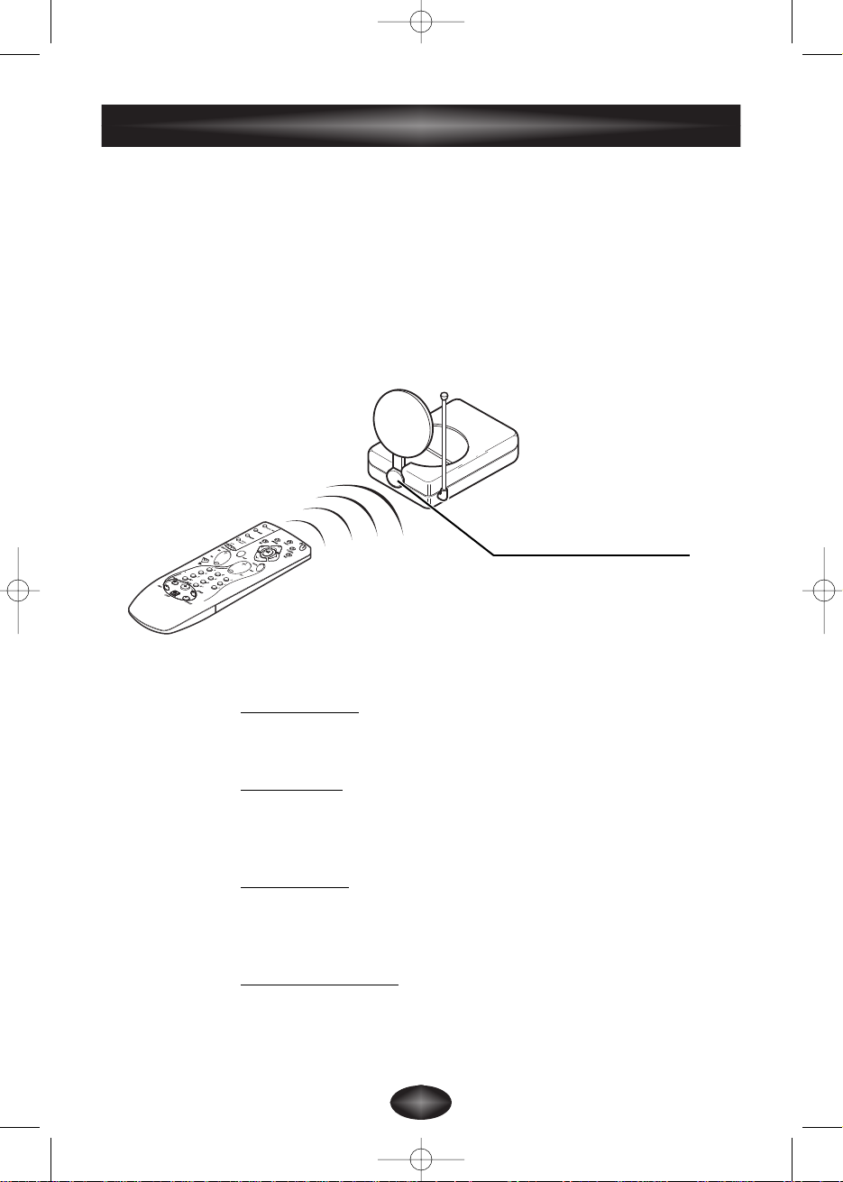
Make sure that you point the
remote control directly at the
receiver's (5) infrared window.
Receiver
VS530C 24/10/00 9:56 Page 8
GB
9
You will obtain the best results from your Video Sender by adjusting the little
dishes (A) correctly. However, certain reflections or other forms of interference
may affect optimum signal transmission. If this is the case, either readjust the
position of the dishes or move the transmitter and receiver slightly until perfect
reception is obtained.
VIDEO IN
AUDIO IN
DC
on off
off
on
If no picture is obtained,
check that the transmitter and the receiver have not been installed in the reverse
order (each unit corresponds either to the input or to the output of the Audio-
Video signal). Check that they have been properly connected and that they are
switched on (on position). Ensure that the channel selector is set to the same
letter on both units.
If transmission is blurred or scrambled
choose another channel but make sure that it is identical on both units.
VS530
video
transmitter
CHANNEL
Improvement of picture and sound
Transmitter
Receiver
VS530C 24/10/00 9:56 Page 9
10
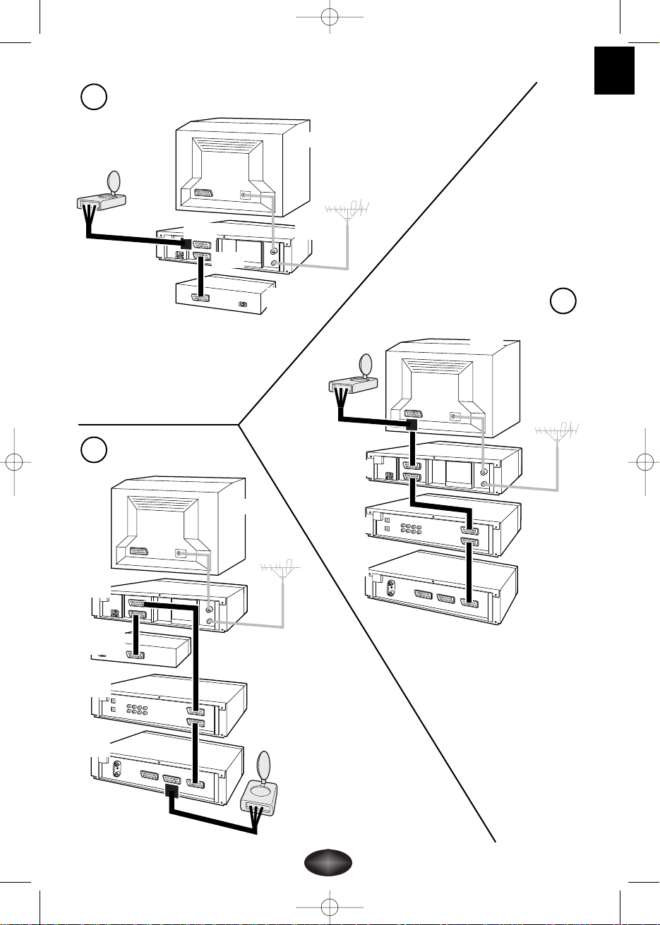
Relay of pictures from several units
If your main set-up consists of several units (video recorder, satellite receiver,
DVD player..) whose pictures and sound you wish to relay to a second television
set, connect them up following the instructions in the diagrams on the following
pages. Usually, the units are connected in series, the last unit having a free scart
connection that you can use for the connection of the transmitter.
!
These diagrams represent some connection possibilities the operation of which
depends on the type of unit, its sockets and the signals it produces.There exist other
connections that you might perhaps wish to try if diagrams 1 to 6 here are not
satisfactory. If this is the case, ask your dealer for assistance.
!
As a general rule, remember to switch off units not in use. Also, refer to the
manufacturers' instructions to see if there are any particularities regarding connection
or use. Certain units may need to have their input scart connection "programmed."
!
In all cases the transmitter must be connected to a scart connection that produces an
Audio-Video signal. Refer to the manufacturer's instructions for confirmation of this.
Diagram (1) allows different pictures to be seen on the 2 television sets or for
the main set to be switched off. Pictures from Canal + can be relayed to the
second television set through the video recorder (equipped with a modulator)
which sends the signal to the Transmitter via the AV1 socket.
To watch Canal + (only in Mono) on the main television set (TV1), select the
television set's video recorder channel and then select the Canal + channel on the
video recorder.
Diagrams (2) and (3) show two other possibilities with or without a decoder.
Diagram (3) relays Canal + pictures via a DVD player and satellite receiver that
are switched off.
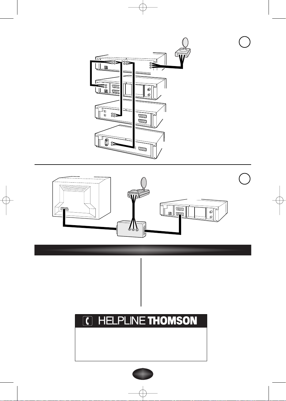
Figure (4) shows another connection scheme starting from an audio-video
amplifier.
Figure (5) represents a further connection scheme using a commercially available
adapter.
VS530C 24/10/00 9:56 Page 10
GB
11
1
3
Transmitter
Transmitter
2
AV1
AV2
Canal +
Decoder
TV1
VCR
TV1
VCR
DVD
SAT
Transmitter
TV1
VCR
Canal +
Decoder
DVD
SAT
VS530C 24/10/00 9:56 Page 11
12
4
Transmitter
5
VCR
AV output
Audio amplifier
DVD
SAT
TV1
VCR
Transmitter
Transmitter
Power supply: 12V DC
VS 530 C/CU (4 channels): A : 2.411 GHz - B : 2.434 GHz
C : 2.464 GHz - D : 2.473 GHz
VS 530 CE (3 channels): B : 2.421 GHz - C : 2.449 GHz
D : 2.477 GHz
VS 530 CF (2 channels): C : 2.464 GHz - D : 2.473 GHz
Remote control return: 433,92 MHz
Transmitter power: 10 mW
Receiver
Power supply: 12V DC
VS 530 C/CU (4 channels): A : 2.411 GHz - B : 2.434 GHz
C : 2.464 GHz - D : 2.473 GHz
VS 530 CE (3 channels): B : 2.421 GHz - C : 2.449 GHz
D : 2.477 GHz
VS 530 CF (2 channels): C : 2.464 GHz - D : 2.473 GHz
Technical characteristics
VS530C/CF/CE/CU-GB-RST/DPAO-10/2000
You can contact THOMSON by dialing: 0845 601 3093,
from 27 November 2000.
(For Great-Britain, all calls will be charged at local rate)
www.thomson-europe.com
VS530C 24/10/00 9:56 Page 12
F
1
Transmetteur vidéo sans fil
Précautions
• Sécurité
Les composants de cet appareil sont sensibles à la chaleur. La
température
maximale ambiante ne doit pas dépasser 35° Celsius.
L’humidité des locaux où est placé l’appareil ne doit pas dépasser un taux
hygrométrique de 85 %. Si vous devez utiliser votre appareil à l’extérieur, évitez
de l’exposer à l’eau de pluie ou aux éclaboussures. Le passage d’une
atmosphère froide à une ambiance chaude peut provoquer de la
condensation. Laissez-la disparaître d’elle-même avant de remettre l’appareil en
marche.
En cas d’absence prolongée, éteignez l’appareil avec l’interrupteur
marche/arrêt. Même à l’arrêt, certains composants restent en contact avec le
réseau électrique. Pour l’isoler complètement vous devez débrancher la fiche
d’alimentation de la prise secteur.
En cas d’orage, il est recommandé d’isoler l’appareil du réseau électrique afin de
ne pas le soumettre à des surcharges électriques ou électromagnétiques qui
peuvent l’endommager. A cette fin, laissez la fiche secteur accessible pour le
débrancher.
Débranchez immédiatement l’appareil si vous constatez qu’il dégage une odeur
de brûlé ou de la fumée. En aucun cas vous ne devez ouvrir l’appareil vous-
même, vous risquez l’électrocution.
• Entretien
Nettoyez l’appareil avec un chiffon doux et un détergent neutre. L’utilisation de
solvants, de produits abrasifs ou de produits à base d’alcool risque d’endommager
l’appareil.
• Réglementation
Cet appareil ne doit être installé qu'à l'intérieur d'un local. Son utilisation est
restreinte aux transmissions radioélectriques privées. Le branchement à un
réseau public ou indépendant ou à une antenne extérieure est interdit.
Cet appareil ne doit en aucun cas être utilisé à des fins industrielles. Il est
uniquement prévu pour un usage domestique.
THOMSON multimedia dégage sa responsabilité en cas d’utilisation
non conforme aux indications de cette notice.
VS530C 24/10/00 9:56 Page 1
2
Principes de fonctionnement
SALON
CHAMBRE
Transmitter
Magnétoscope, récepteur satellite, ...
Receiver
Télécommande du
magnétoscope, récepteur
satellite, ... ou télécommande
universelle.
VS530C 24/10/00 9:56 Page 2
F
3
off
on
VIDEO IN
REMOTE
OUT
AUDIO IN
DC
DVD
TV
Magnétoscope
Camescope
Lecteur Video-disc
Récepteur et décodeur
Satellite/Câble
Amplificateur A/V
Le Video Sender VS 530 C,VS 530 CU, VS 530 CE ou VS 530 CF permet
de diffuser un signal Audio-Video à partir de votre installation principale vers un
second téléviseur installé dans une autre pièce et équipé d’une prise
péritélévision. L’installation principale est l’endroit où vous avez regroupé la
plupart de vos appareils (téléviseur, magnétoscope, récepteur satellite, lecteur
DVD, ...).Vous pourrez commander les appareils depuis la pièce où se trouve le
second téléviseur à l’aide de leurs télécommandes, ou avec une télécommande
universelle.
Vous pourrez aussi utiliser le Video Sender pour surveiller votre bébé en
raccordant l’émetteur à un camescope dirigé vers son lit et le récepteur à un
téléviseur ou un moniteur que vous placerez près de vous. Le branchement du
camescope à l’émetteur nécessite un adaptateur péritélévision / cinch ou un câble
cinch / cinch, (selon les appareils) non fourni.
La diffusion de musique est possible si vous raccordez l’émetteur à un
amplificateur (AUDIO OUT) et le récepteur à un autre amplificateur (AUDIO IN)
dans une autre pièce. Dans ce cas vous devrez vous procurer 1 câble cinch / cinch
non fourni.
VS530C 24/10/00 9:56 Page 3

4
Installation de l’émetteur (Transmitter)
Dépliez le volet de la couverture de cette notice afin de visualiser les
composants du Video Sender et reportez-vous au schéma de la page 5.
1. Placez l’émetteur (1) sur, ou à proximité,du téléviseur et de l’appareil dont vous
souhaitez diffuser les images et le son et raccordez-le à l’aide du cordon
(2 A et B) en respectant les couleurs des 3 fiches cinch (rouge et blanche pour
l’audio, jaune pour la vidéo). Raccordez la fiche péritélévision à une des prises
du téléviseur (AV1 de préférence).
Procurez-vous un cordon SCART-Péritélévision (non fourni) et raccordez
l’appareil, dont vous voulez diffuser les images et le son, à l’adaptateur 2B déjà
branché au téléviseur (voir repère
*
de la page 5).
2. Déployez l’antenne parabolique de l’émetteur (1) et orientez-la en direction de
la pièce du second téléviseur (TV2).
3. Redressez l’antenne télescopique de l’émetteur (1).
4. Installez le cordon (4) en suivant ces étapes :
- raccordez la fiche jack dans la prise
REMOTE OUT.
- déroulez le cordon et placez une cellule à proximité de la fenêtre infrarouge
de l'appareil à commander (magnétoscope ou autre)
- demandez à une personne d'utiliser la télécommande de l'appareil à
commander depuis la pièce où se trouve le second téléviseur (TV2).
- en déplaçant la cellule devant l'appareil à commander vous pourrez
déterminer l'emplacement qui permet sa commande depuis l'autre pièce.Vous
devrez-y coller la cellule. Généralement il s'agit d'une zone transparente plus
ou moins grande située en façade.
5. Enlevez le papier de protection de la partie auto-collante des cellules
infrarouges du cordon (4) et collez-les sur les fenêtres infrarouges des appareils
à télécommander et raccordez la fiche jack à la prise correspondante
(REMOTE OUT) de l’émetteur (1). Le cordon est équipé de 3 cellules afin de
vous permettre de diffuser les images et le son de 3 appareils connectés au
téléviseur (TV1).
6. Branchez l’alimentation secteur (3) à l’émetteur et à une prise secteur
220/240V ~ 50 Hz.
VS530C 24/10/00 9:56 Page 4
F
5
AUDIO IN DC 12VVIDEO IN
REMOTE
OUT
2
1
3
4
220/240V
~ 50 Hz
TV1
*
A
B
VS530C 24/10/00 9:56 Page 5

6
Dépliez le volet de la couverture de cette notice afin de visualiser les
composants du Video Sender et reportez-vous au schéma de la page 7.
1. Placez le récepteur (5) sur, ou à proximité du second téléviseur.
2. Raccordez le récepteur (5) au second téléviseur à l’aide du cordon (6) en
suivant les mêmes recommandations que pour l’émetteur.
3. Déployez l’antenne parabolique du récepteur (5) et orientez-la en direction du
téléviseur principal (TV1).
4. Redressez l’antenne télescopique du récepteur (5)
.
5. Branchez l’alimentation secteur (7) au récepteur et à une prise secteur
220/240V ~ 50 Hz
.
! L’ANTENNE PARABOLIQUE permet la diffusion du signal Audio-Video sur
une portée maximum de 30 mètres en champ libre. A l’intérieur d’une habitation
cette portée est inférieure et dépend des matériaux que les ondes auront à
franchir.
! L’ANTENNE TÉLESCOPIQUE permet la commande de l’appareil dont vous
souhaitez voir les images à partir de la pièce où se trouve le second téléviseur
(TV2).
! L’ALIMENTATION de l’émetteur (1) possède une prise différente de celle de
l’alimentation du récepteur (7).
Installation du récepteur (Receiver)
VS530C 24/10/00 9:56 Page 6
 Loading...