

Page 1
Transmitters TH7
Series SC250 / DP / LP
Instructions manual
R-MI-TH7 Rev.: 1 English version
Page 2

PREFACE
Thank you for choosing the TH7 transmitter from Tecfluid S.A.
This instruction manual allows the connection, commissioning and
operation of the TH7 transmitter. It is recommended to read it before
using the equipment.
WARNINGS
This document shall not be copied or disclosed in whole or in
any part by any means, without the written permission of
Tecfluid S.A.
Tecfluid S.A. reserves the right to make changes as deemed
necessary at any time and without notice, in order to improve
the quality and safety, with no obligation to update this manual.
Make sure this manual goes to the end user.
Keep this manual in a place where you can find it when you
need it.
In case of loss, ask for a new manual or download it directly
from our website www.tecfluid.com Downloads section.
Any deviation from the procedures described in this instruction
manual, may cause user safety risks, damage of the unit or
cause errors in the equipment performance.
Do not modify the equipment without permission. Tecfluid S.A.
is not responsible for any problems caused by a change not
allowed. If you need to modify the equipment for any reason,
please contact us in advance.
2
Page 3

TABLE OF CONTENTS
1 INTRODUCTION ................................................................................... 4
2 MODELS ................................................................................................ 4
2.1 TH7 ............................................................................................. 4
2.2 TH7H .......................................................................................... 4
2.3 TH7T and TH7TH ...................................................................... 4
3 MOUNTING THE TRANSMITTER IN AN EXISTING EQUIPMENT ...... 4
3.1 Kit contents ............................................................................... 4
3.2 Preparing the kit ....................................................................... 5
3.3 Assembling the kit TH7 or TH7H ............................................. 5
3.4 Assembling the kit TH7T or TH7TH ........................................ 6
3.5 Electrical conection ................................................................. 6
3.6 Mounting ................................................................................... 7
4 ELECTRICAL CONNECTION ............................................................... 7
4.1 Power supply and analog output ............................................ 8
4.2 Digital output ............................................................................ 8
4.2 Reset input ................................................................................ 9
5 4-WIRE CONNECTION ......................................................................... 9
6 TRANSMITTERS WITH HART PROTOCOL ........................................ 10
6.1 Additional functions with HART communication .................. 11
6.2 HART communication characteristics ................................... 11
7 ”WRITE PROTECT” .............................................................................. 12
8 MAINTENANCE .................................................................................... 12
9 ASSOCIATED SOFTWARE WINSMETER TH7 ................................... 12
9.1 USB cable connection and drivers installation ..................... 12
9.2 Port connection ......................................................................... 13
9.3 Access to installation and programming ................................ 14
9.4 Visualization ............................................................................. 16
9.5 Firmware update ....................................................................... 17
10 TECHNICAL CHARACTERISTICS ........................................................ 18
10.1 Power supply ........................................................................... 18
10.2 Outputs ...................................................................................... 18
10.3 General characteristics ............................................................ 18
10.4 Safety characteristics .............................................................. 18
11 TROUBLESHOOTING .......................................................................... 19
3
Page 4

1 INTRODUCTION
TH7 transmitters are microprocessed electronic position transducers. The instrument uses
the Hall effect to capture the field of a magnet. The resulting signal, after the microcontroller processing, is converted into a current signal of 4-20 mA in a 2-wire loop. This
signal is proportional to the flow rate or the level height inside a tank.
2 MODELS
2.1 TH7
It is a 4 to 20 mA transmitter proportional to flow rate that incorporates a synchronized
pulse output. 4 mA corresponds to beginning of the scale. 20 mA corresponds to full
scale. If the transmitter is installed in a flow meter (series SC250 / DP), the cut off value
can be programmed (see section 9.3 in page 16). By default, the cut off corresponds to
the first point on the scale after the zero point.
In the case of level measurement (LP series), the current range corresponds to the scale
at all the points. There is no cut off.
2.2 TH7H
It is a TH7 transmitter that incorporates HART protocol compatibility. With this protocol the
user can change the measuring range of the 4-20 mA loop, and data like flow rate and
accumulated volume.
2.3 TH7T and TH7TH
They are the equivalent models to those of the sections 2.1 and 2.2, but in addition they
include a 8-digit totalizer (7 entire numbers and 1 decimal).
3 MOUNTING THE TRANSMITTER IN AN EXISTING EQUIPMENT
When the transmitter is to be fitted to an existing device, please follow these steps.
3.1 Kit contents
The kit contains the following elements:
Kit TH7 or TH7H
Quantity Material Position
1
Transmitter
4 Screw DIN7985 M 3 x 4 A2 2
2 O-rings Ø 16 x 18,5 x 1,25 mm NBR-70 3
2 Cable gland IP68 4
2 Cable gland blanking plug 5
Kit TH7T or TH7TH
Quantity Material Position
1
Totalizer
2 Screw DIN7982 B-2,2 x 9 Nº2 A2 2
1
1
4
Page 5
In the kits, the O-rings (3) and the blanking plugs (5) are not provided as loose parts. They
are incorporated in the cable glands (4).
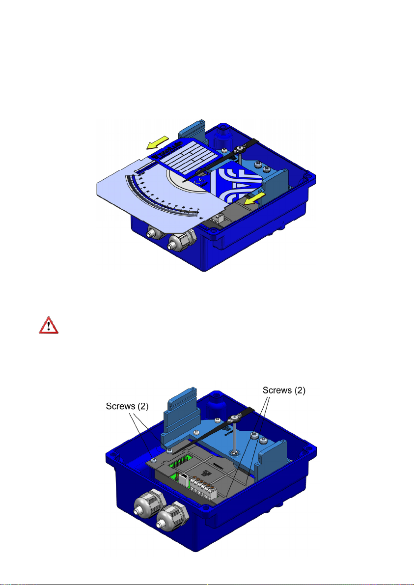
3.2 Preparing the kit
Remove the cover, unscrewing the four screws "Allen" M5 and plastic washers, in the
back side of the indicator housing, using a 4 mm Allen key.
Slide the scale plate in the direction indicated in the figure, until it is released from the slot.
Ensure that the O-rings (3) are placed in the thread of the gland (4). If not, they should be
placed. Remove the plugs from the indicator box with a flat screwdriver and replace them
by the two cable glands.
The cable glands that are not expected to be used should be left with the blanking plug
(5) placed to preserve watertight.
3.3 Assembling the kit TH7 or TH7H
Screw the transmitter as shown in the figure.
5
Page 6

3.4 Assembling the kit TH7T or TH7TH
Enter the circuit through the slot until it stops, and then screw it as shown in the figure.
The flat ribbon connecting the transmitter to the totalizer should be connected as in the
figure below.
3.5 Electrical connection
Do it according to section 4 of this manual.
6
Page 7

3.6 Mounting
Slide the scale plate through the top slot until it stops as shown in the figure.
Reassemble the cover with the four screws "Allen" M5 and the plastic washers.
4 ELECTRICAL CONNECTION
For the electrical connection, the transmitter has a screw terminal strip.
For the electrical installation it is recommended to use multiple conductor cables with
individual cable sections in the order of 0.25 to 0.5 mm
connect.
A twisted pair wiring should be used to avoid electrical interferences in the 4-20 mA loop.
In some instances, shielded cable may be necessary.
Before starting the installation, check that the cable glands are the right size for the cables
to be used, this will guarantee the instrument will stay watertight. The M16x1.5 cable
glands used are for cables with outside diameters between 6 mm and 10 mm.
Peel the outside insulation to free the inner cables. It is recommended to tin the ends of
the wires to avoid loose ends. Pass the cables through the cable glands and screw down
in the corresponding positions of the terminal strip. Once the wiring is finished make sure
that the cables are well gripped by the cable glands to maintain the degree of protection.
The cable glands must be always closed. Entry of dust or some types of vapors can
damage the internal system of bearings and therefore the equipment.
To help in the wiring of the equipment, the description of the terminals is marked on the
printed circuit next to the terminal strip.
2
in order to make it easier to
Pulses
7
Page 8

Before connecting the power supply, you must be sure that the supply voltage is the
correct one for the installation. The power supply voltage is indicated on the label of the
transmitter.
4.1 Power supply and analog output
The connection is made in the terminal block. The positive terminal of the power supply is
connected to the position + and the positive terminal of the load in the position -. The
negative terminals of the power supply and the load are connected together. The
instrument works in a 2-wire system, that is, the supply and signal line is the same. It is
recommended to use a twisted pair wiring or shielded cable to avoid interferences in the
current loop.
4.2 Digital output
The pulse output is connected in the positions D and S of the terminal block. The output is
an N channel MOSFET transistor isolated from the rest of the circuit and potential free.
The S terminal is the source and the D terminal is the drain.
By means of the Winsmeter TH7 software, the digital output or the pulse output can be
programmed (see section 9.3 in page 16).
8
Page 9

Example of the connection of the pulse output to a PLC
4.3 Reset input
The terminals marked as RESET are a reset input for the totalizer. It can be connected to
a normally open potential free contact. It is important that the contact works well with low
level signals, to avoid noise effects.
Note: The reset terminals are not isolated from the rest of the circuit. They may not be
connected to other equipment.
5 4-WIRE CONNECTION
If direct current power supply for the transmitter is not available in the installation, it will be
necessary to incorporate an additional power supply as in the following figure.
9
Page 10

6 HART TRANSMITTERS
The TH7H and TH7TH transmitters have a modem for HART communication.
TH7H transmitters are fully compatible with the HART Server software from HART
Communication Foundation.
Tecfluid S.A. do not guarantee that the TH7H transmitter is compatible with the different
servers on the market.
When connecting the transmitter, an external resistor (R ext.) should be included. Its
minimum value is be 200 and the maximum value depends on the power supply as
follows:
In this case the power supply voltage needs to be 18 VDC minimum.
In order to establish HART communication, it is necessary to connect a terminal or PC
with a HART modem, in one of the points indicated in the following figure.
10
Page 11

6.1 Additional functions with HART communication
By means of the implemented commands, the user can obtain the following information:
Flow rate value in the scale units
Totalizer value (even if the equipment does not have a display).
Reset or writing of a totalizer value.
Change of beginning and end of scale of the current loop.
Possibility of writing tags and messages into the instrument.
6.2 HART communication characteristics
The detail of the characteristics with respect to the HART communication are available in
the corresponding “Field Device Specification” document.
Summary of the main communication characteristics:
Manufacturer, Model and Revision Tecfluid S.A., TH7H, Rev. 0
Device type Transmitter
HART revision 6.0
Device Description available No
Number and type of sensors 1
Number and type of actuators 0
Number and type of host side signals 1, 4 – 20 mA analog
Number of Device Variables 2
Number of Dynamic Variables 1
Mappable Dynamic Variables No
Number of Common Practice Commands 5
Number of Device Specific Commands 0
Bits of Additional Device Status 12
Alternative working modes? No
Burst mode? No
Write Protection? Yes
Electrical characteristics referred to the analog loop and communications:
Reception impedance:
Rx > 3,3 MΩ
Cx < 1000 pF
11
Page 12

7 “WRITE PROTECT”
The instrument has a jumper that can be used to avoid changes in the configuration.
When the jumper is connected the instrument can be configured via HART. When the
jumper is removed, “Write Protect” is activated for HART, thus avoiding any changes in
the configuration.
8 MAINTENANCE
No special maintenance is required.
9 ASSOCIATED SOFTWARE WINSMETER TH7
By means of this associated software the transmitter can perform the following functions,
working in a comfortable and intuitive way.
Complete re-calibration of the transmitter according to the scale of the instrument.
Programming of 4 and 20 mA values
Filter and cut off programming
Totalizer reset or adjustment of a desired value
Configuration of the digital output as pulse output or alarm
Such software can be downloaded from section “Downloads” of the Tecfluid S.A. website.
9.1 USB cable connection and drivers installation
Extract the files from the winsmeterTH7.zip to a new system folder.
Execute the Setup.exe file and follow the steps for the installation.
In order to connect the converter to a computer an USB cable is required. This cable is type
A at one end and mini USB type B at the other (cable not supplied).
The first step to make the connection is to open the cover of the indicator housing by
removing the four screws "Allen" M5 and plastic washers on the back of the housing.
After removing the graduated scale plate sliding it through the slots, the USB connector is
visible at the bottom of the housing.
12
Page 13

Connect the USB cable at one end to the transmitter and at the other to the computer where
the software is installed.
Power on the electronic converter.
Execute the program WinsmeterTH7 following the sequence Start – Programs – Tecfluid
S.A. - WinsmeterTH7.
9.2 Port connection
In the "Port" section, choose the appropriate port for the converter. This will appear with the
name of the port followed by TH7 and its serial number. Then click "Open".
13
Page 14

Once the port is open, the button "Open" in the "Calibration" and “Programming” sections
activates.
9.3 Access to Calibration and Programming
In order to access the tab "Calibration", you must enter a password.
The default password is calib, and it can be changed using the boxes on the right of the
"Calibration" section.
Likewise, to access the tab "Programming" it is necessary to enter the password which by
default is program. This can be changed using the boxes on the right of the "Programming"
section.
14
Page 15

Once the password is written, press "Enter" or "Open", and the Calibration or Programming
tab will open. At the bottom of each section the text "Calibration tab open" or "Programming
tab open" will be displayed
To enter the Installation window, just click the corresponding tab.
In the calibration window a complete re-calibration of the transmitter according to the scale
plate can be done.
The first step is to choose the scale units, then the specific units.
In the combo N. points the number of points with which the calibration will be performed is
selected. The minimum is 10 and the maximum 16.
With these data, the boxes P0 ... P10 to P16 are filled with the values of the scale in which
the adjustment will be made.
To perform the calibration, the instrument must be in its operating position.
Depending on the instrument in question, move the float or the disc until the needle points
each calibration point, and press the "Calibrate" button of the corresponding point.
Once calibrated every point, to send all the data to the transmitter TH7, click the "Send"
button. The data is then stored in the transmitter memory.
15
Page 16

Likewise, to enter into the programming window, just click the corresponding tab.
Changing the parameters of this screen, (see previous page) you can program the different
functions of the equipment.
In the box Totalizer units power can be selected. The power allows to multiply or divide by a
factor the totalizer speed, as well as the pulse output.
In the box Digital output this output can be configured as pulse output or as alarm. In the
latter case, the activation and deactivation values for the alarm can be programmed.
In the box Current loop the values of flow rate equivalent to 4 and 20 mA can be
programmed. These values do not have to be the beginning of scale and end of scale
values.
In the box Flow rate the values of cut off and filter can be changed.
To program this data to the transmitter, press the “Send” button. The programming data will
be stored in the memory of the transmitter.
Regardless of the programming process, in the box Totalizer value the value of the totalizer
can be changed.
9.4 Visualization
When the communication with the computer port is established (see section 9.2), the tab
"Visualization" opens. This tab lets you view real-time flow rate, totalizer and velocity values,
as well as the current value of the analog output and the status of the digital output if
configured as alarm.
It is an intuitive tool to verify that the instrument has been installed and programmed
correctly.
16
Page 17

By means of the "Record" button, you can store data in different computer files, which can
then be processed by other software.
9.5 Firmware updates
New firmware updates can be published in the website. These updates contain
improvements or bug fixes that make the equipment operates at best conditions.
The updates can be downloaded from the section “Downloads” of Tecfluid S.A. website
To update the equipment, go to menu “Firmware” - “Update”, and a screen with the button
“File” will appear. Pressing this button system can be accessed. The downloaded file has to
be searched there.
17
Page 18

Once the file is selected, press the “Program” button. A message “Programming device” will
appear.
The process takes about 90 seconds, after which the message “Device programmed” will
appear.
From this moment, the converter TH7 already has the new version of Firmware.
10 TECHNICAL CHARACTERISTICS
10.1 Power supply
2 wire.
Minimum voltage (TH7 y TH7T): 0.02 Z + 12 (Volt) (Z is the load in the current
The minimum value is 12 VDC for Z=0 Ohm.
Minimum voltage (TH7H y TH7TH): 0..02 (Z+Rext) + 14 (Volt) (Z is the load in the
The minimum value is 18 VDC for Z=0 Ohm and
Maximum voltage: 36 VDC
Consumption: maximum 20 mA
10.2 Outputs
Analog output: 4 - 20 mA, factory calibrated
Maximum load in the 4-20 loop: 1.1 k (at 36 VDC supply voltage)
Pulse output: MOSFET transistor N channel potential free
Maximum frequency: 6 Hz.
Pulse duration: Aprox. 62.5 ms.
loop in Ohm).
current loop in Ohm).
Rext=200 Ohm.
: 200 mA
I
max
18
Page 19

Totalizer: 8 digits. (7 + one decimal. Reset by means of
10.3 General characteristics
Housing ingress protection: IP65
Cable gland: M16 x 1.5
Ambient temperature: -5ºC ...+70 ºC
Precision (analog output respect
the magnetic field): < 0.6 %
10.4 Safety characteristics
This material conforms with the following directives:
2004/108/EC Electromagnetic Compatibility.
2002/96/EC Waste electrical and electronic equipment.
potential free contact).
(optional IP67 with AISI 316L enclosure)
11 TROUBLESHOOTING
Problem Possible cause Solution
The analog output gives
always 0 mA
The indicator needle
rubs on the scale plate
The mechanical
indication does not
match the 4 -20 mA
output
The totalizer does not
accumulate
Disconnected cables Check the connection
Straighten it out by bending it
The meter has been hit or dropped
The transmitter is not programmed
Wrong connection
Incorrect configuration
slightly until it is separated by
between 2-3 mm from the reading
scale surface
Re-calibrate with Winsmeter TH7
software
Check the flat ribbon connector
Check the programming with
Winsmeter TH7 software
The pulse output does
not work
Note: In all cases, check that there is no friction between the moving system of the
needle and the connecting wires of the transmitter.
When the needle of the instrument is manipulated, the accuracy of the transmitter can be
reduced.
Wrong connection
Programmed frequency too high
19
Check the connection
Check the programming with
Winsmeter TH7 software
Page 20

WARRANTY
Tecfluid S.A. guarantees all the products for a period of 24 months from their sale, against all faulty
materials, manufacturing or performance. This warranty does not cover failures which might be
imputed to misuse, use in an application different to that specified in the order, the result of service
or modification carried out by personnel not authorized by Tecfluid S.A., wrong handling or
accident.
This warranty is limited to cover the replacement or repair of the defective parts which have not
damaged due to misuse, being excluded all responsibility due to any other damage or the effects
of wear caused by the normal use of the devices.
Any consignment of devices for repair must observe a procedure which can be consulted in the
website www.tecfluid.com, “After-Sales” section.
All materials sent to our factory must be correctly packaged, clean and completely exempt of any
liquid, grease or toxic substances.
The devices sent for repair must enclose the corresponding form, which can be filled in via website
from the same “After-Sales” section.
Warranty for repaired or replaced components applies 6 months from repair or replacement date.
Anyway, the warranty period will last at least until the initial supply warranty period is over.
TRANSPORTATION
All consignments from the Buyer to the Seller´s installations for their credit, repair or replacement
must always be done at freight cost paid unless previous agreement.
The Seller will not accept any responsibility for possible damages caused on the devices during
transportation.
TecfluidS.A.
NarcísMonturiol33
08960SantJustDesvern
Barcelona
Tel:+34933724511
QualityManagementSystemISO9001cerfiedby
PressureEquipmentDirecve97/23/CEcerfiedby
ATEXEuropeanDirecve94/9/CE
cerfiedby
Fax:+34934734449
tecfluid@tecfluid.com
HART®isaregisteredtrademarkofHARTCommunicaonFoundaon
www.tecfluid.com
Thetechnicaldatadescribedinthismanualissubjecttomodificaonwithoutnoficaonifthetechnicalinnovaonsin
themanufacturingprocessessorequire.
20
 Loading...