

Page 1
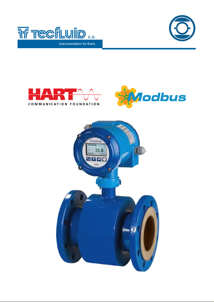
Communication
protocols for
MX4B and MX4H
converters
Instructions manual
R-MI-MX4COM Rev.: 0 English version
Page 2

PREFACE
Thank you for choosing the MX4 converter from Tecfluid S.A.
This instruction manual allows the connection, commissioning and
operation of the MX4 converter with HART or Modbus
communications option. It is recommended to read it before using
the equipment.
WARNINGS
This document shall not be copied or disclosed in whole or in
any part by any means, without the written permission of
Tecfluid S.A.
Tecfluid S.A. reserves the right to make changes as deemed
necessary at any time and without notice, in order to improve
the quality and safety, with no obligation to update this manual.
Make sure this manual goes to the end user.
Keep this manual in a place where you can find it when you
need it.
In case of loss, ask for a new manual or download it directly
from our website www.tecfluid.com Downloads section.
Any deviation from the procedures described in this instruction
manual, may cause user safety risks, damage of the unit or
cause errors in the equipment performance.
Do not modify the equipment without permission. Tecfluid S.A.
is not responsible for any problems caused by a change not
allowed. If you need to modify the equipment for any reason,
please contact us in advance.
2
Page 3

TABLE OF CONTENTS
1 INTRODUCTION ................................................................................... 5
2 MODBUS DATA MODEL ....................................................................... 5
3 MODBUS FUNCTIONS ......................................................................... 5
3.1 Function “Read Input Registers” ........................................... 5
3.2 Function “Read Holding Registers” ....................................... 5
3.3 Function “Write Single Register” ........................................... 5
3.4 Function “Write Multiple Registers” ....................................... 5
4 MODBUS IN MX4B CONVERTER ....................................................... 5
4.1 Data access .............................................................................. 5
4.2 Register adresses .................................................................... 6
5 DEVICE DATA ACCESS ...................................................................... 7
5.1 Flow rate ................................................................................... 7
5.2 Total ........................................................................................... 7
5.3 Flow rate 4 mA .......................................................................... 7
5.4 Flow rate 20 mA ......................................................................... 8
5.5 Totalizer units ........................................................................... 8
5.6 Flow rate units ........................................................................... 8
5.7 Filter ....................................................................................... 9
5.8 Status ......................................................................................... 9
6 EXAMPLES ........................................................................................... 10
7 ELECTRICAL CONNECTION ............................................................... 13
8 CONVERTER PROGRAMMING ........................................................... 15
8.1 Slave address ........................................................................... 16
8.2 Baud rate ................................................................................... 16
8.3 Parity ....................................................................................... 16
8.4 Stop bits ..................................................................................... 16
8.5 Timeout ..................................................................................... 17
9 ERRORS ............................................................................................... 17
MODBUS
3
Page 4

HART
1 INTRODUCTION ................................................................................... 18
2 DEVICE IDENTIFICATION .................................................................... 18
3 CURRENT LOOP DESCRIPTION ........................................................ 18
3.1 Current loop connection ......................................................... 19
4 VARIABLES .......................................................................................... 20
4.1 Device variables ....................................................................... 20
4.2 Dynamic variables ................................................................... 20
5 COMMANDS ......................................................................................... 20
5.1 Universal commands ............................................................... 20
5.2 Common practice commands ................................................. 22
6 BURST MODE ....................................................................................... 22
7 OPERATION MODES ........................................................................... 22
8 WRITE PROTECTION .......................................................................... 22
4
Page 5

MODBUS
1 INTRODUCTION
Modbus is a communication protocol commonly used to connect industrial electronic
devices. It is based in a master-slave architecture.
Protocol Modbus RTU uses a compact binary representation of the data and ends its
frames with a cyclic redundancy check code.
2 MODBUS DATA MODEL
Modbus bases its data model in four tables with differentiated characteristics.
Discrete Inputs: Read only bits. This type of data can be read by a master device. They
are not implemented in Tecfluid Modbus protocol devices.
Coils: Read write bits. These data can be read or written by a master device. They are
not implemented in Tecfluid Modbus protocol devices.
Input Registers: 16 bits read only data. This type of data can be read by a master
device.
Holding Registers: 16 bits read write data. These data can be read or written by a
master device.
3 MODBUS FUNCTIONS
Modbus functions allow access to a device in order to read or modify the value of some
of its data. The Tecfluid devices support the following functions:
3.1 Function “Read Input Registers” 0x04h
Gets the value of the "Input Registers" of one or more consecutive addresses of the
selected device.
3.2 Function “Read Holding Registers” 0x03h
Gets the value of the "Holding Registers" of one or more consecutive addresses of the
selected device.
3.3 Function “Write Single Register” 0x06h
Writes the value of a "Holding register" to the address of the selected device.
3.4 Function “Write Multiple Registers” 0x10h
Writes the value of the "Holding Registers" to several consecutive addresses of the
selected device.
4 MODBUS IN MX4B CONVERTER
4.1 Data access
The data that can be accessed in a MX4B converter and their format are the following:
5
Page 6
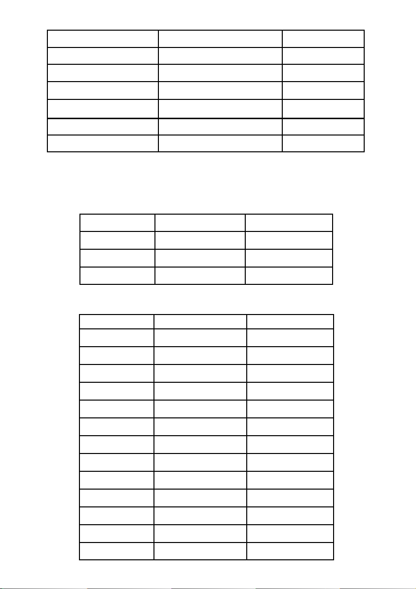
Data Format Type
Flow rate Floating point IEEE 754 32 bits Read only
Total Floating point IEEE 754 32 bits Read write
Analog output 4 mA value Floating point IEEE 754 32 bits Read write
Analog output 20 mA value Floating point IEEE 754 32 bits Read write
Integration filter Integer 16 bits Read write
Status Integer 16 bits Read only
4.2 Register addresses
The addresses for the different data are the following:
Input Registers (Read only)
Access (Hex) Data Type
0x2000 Flow rate MSB Floating point
0x2001 Flow rate LSB Floating point
0x2002 Reserved ---
Holding Registers (Read write)
Address (Hex) Data Type
0x3000 Totalizer MSB Floating point
0x3001 Totalizer LSB Floating point
0x3002 Flow rate 4 mA MSB Floating point
0x3003 Flow rate 4 mA LSB Floating point
0x3004 Flow rate 20 mA MSB Floating point
0x3005 Flow rate 20 mA LSB Floating point
0x3006 Totalizer units Integer
0x3007 Flow rate units Integer
0x3008 Filter Integer
0x3009 Status Integer
0x300A Reserved ---
0x300B Reserved ---
0x300C Reserved ---
6
Page 7

5 DEVICE DATA ACCESS
NOTE: The floating point data use two registers. It is recommended to access them with
an unique message instead of two consecutive readings or writings.
When using the writing function "Write Single Register" to write a data in floating point, it
is imperative to write the lower address first and then the upper one. If done in reverse
order generates the error "INVALID DATA VALUE" and the value is not programmed into
the device until the two registers that compose the data have been completed.
5.1 Flow rate
Description: Instantaneous flow rate of the converter.
The flow rate data contains the numeric value of the instantaneous flow rate
corresponding to flow rate units programmed into the device. Variable is a floating point
32-bit IEEE 754. To access this data on the device is necessary to access two 16-bit
registers.
The address 0x2000h corresponds to the most significant 16 bits and address 0x2001h to
the least significant 16 bits.
Supported functions: Read Input Registers. (0x04)
Addresses: 0x2000 16 bit Flow rate MSB
0x2001 16 bit Flow rate LSB
5.2 Total
Description: Totalizer value.
The Total data contains the numerical value of the cumulative total corresponding to the
units programmed into the device. Variable is a floating point IEEE 754 32 Bits. To access
this data on the device is necessary to access two 16-bit registers.
The address 0x3000h corresponds to the most significant 16 bits and address 0x3001h to
the least significant 16 bits.
Supported functions: Read Holding Registers. (0x03h)
Write Single Register. (0x06h)
Write Multiple Registers. (0x10h)
Addresses: 0x3000h 16 bit Total MSB
0x3001h 16 bit Total LSB
5.3 Flow rate 4 mA
Description: Flow rate beginning of scale of analog output.
Flow rate 4 mA contains the numerical value of the flow rate corresponding to the
beginning of the scale of the analog output (4 mA) in the flow rate units programmed into
the device.
Variable is a floating point 32-bit IEEE 754. To access this data on the device is
necessary to access two 16-bit registers.
The address 0x3002h corresponds to the most significant 16 bits and address 0x3003h to
the least significant 16 bits.
Supported functions: Read Holding Registers. (0x03h)
Write Single Register. (0x06h)
Write Multiple Registers. (0x10h)
Addresses: 0x3002h 16 bit 4 mA MSB
0x3003h 16 bit 4 mA LSB
7
Page 8

5.4 Flow rate 20 mA
Description: Flow rate end of scale of analog output.
Flow rate 20 mA contains the numerical value of the flow rate corresponding to the end of
the scale of the analog output (20 mA) in the flow rate units programmed into the device.
Variable is a floating point 32-bit IEEE 754. To access this data on the device is
necessary to access two 16-bit registers.
Address 0x3004h corresponds to the most significant 16 bits and address 0x3005h to the
least significant 16 bits.
Supported functions: Read Holding Registers. (0x03h)
Write Single Register. (0x06h)
Write Multiple Registers. (0x10h)
Addresses: 0x3004h 16 bit 20 mA MSB
0x3005h 16 bit 20 mA LSB
5.5 Totalizer units
Description: Contains the code corresponding to the totalizer units of the converter. It is
a 16 bits integer data type (see totalizer code table).
Supported functions: Read Holding Registers. (0x03h)
Write Single Register. (0x06h)
Write Multiple Registers. (0x10h)
Address: 0x3006h 16 bit Totalizer units
Units Data (Hex)
US gal. 0x0001
UK gal. 0x0002
l 0x0003
3
m
0x0004
Totalizer code table
5.6 Flow rate units
Description: Contains the code corresponding to the flow rate units of the converter. It is
a 16 bits integer data type (see flow rate code table).
Supported functions: Read Holding Registers. (0x03h)
Write Single Register. (0x06h)
Write Multiple Registers. (0x10h)
Address: 0x3007h 16 bit Flow rate units
8
Page 9
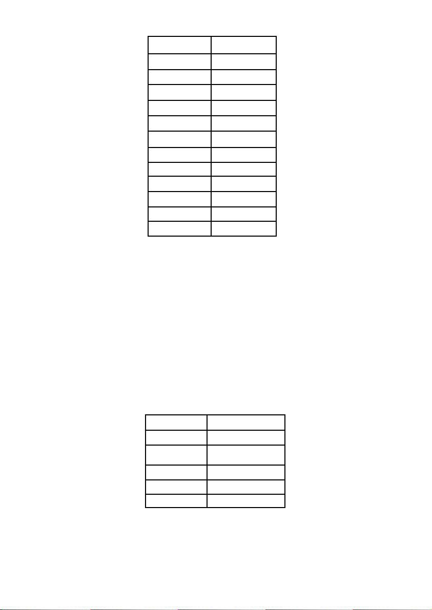
Units Data (Hex)
US Gal/h 0x0001
US Gal/min 0x0002
US Gal/s 0x0003
Gal/h 0x0004
Gal/min 0x0005
Gal/s 0x0006
l/h 0x0007
l/min 0x0008
l/s 0x0009
3
/h 0x000A
m
3
m
/min 0x000B
3
/s 0x000C
m
Flow rate code table
5.7 Filter
Description: Contains the integration time value between 0 and 40 s.
Supported functions: Read Holding Registers. (0x03h)
Write Single Register. (0x06h)
Write Multiple Registers. (0x10h)
Address: 0x3008h 16 bit Filter
5.8 Status
Description: Contain the status bits of the converter.
Supported functions: Read Holding Registers. (0x03h)
Address: 0x3009h 16 bit
Bit Status
0 Empty pipe
1
Coil cable
disconnected
2 Status relay 1
3 Status relay 2
4 .. 15 Reserved
Note: Bits 3-0 can not be modified. They are read only.
9
Page 10
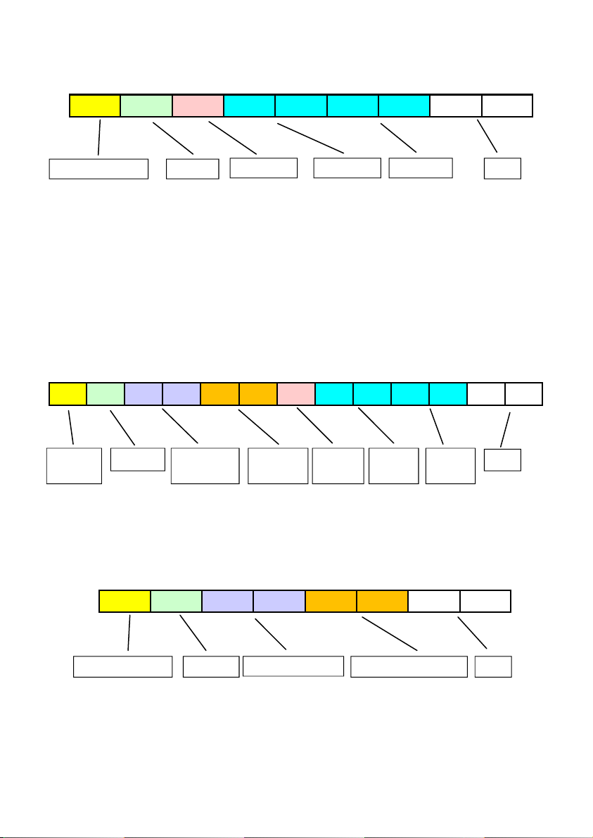
6 EXAMPLES
NOTE: In all examples, where said CRC refers to “Cyclic redundancy check”, that is an
error detecting code sent at the end of each frame.
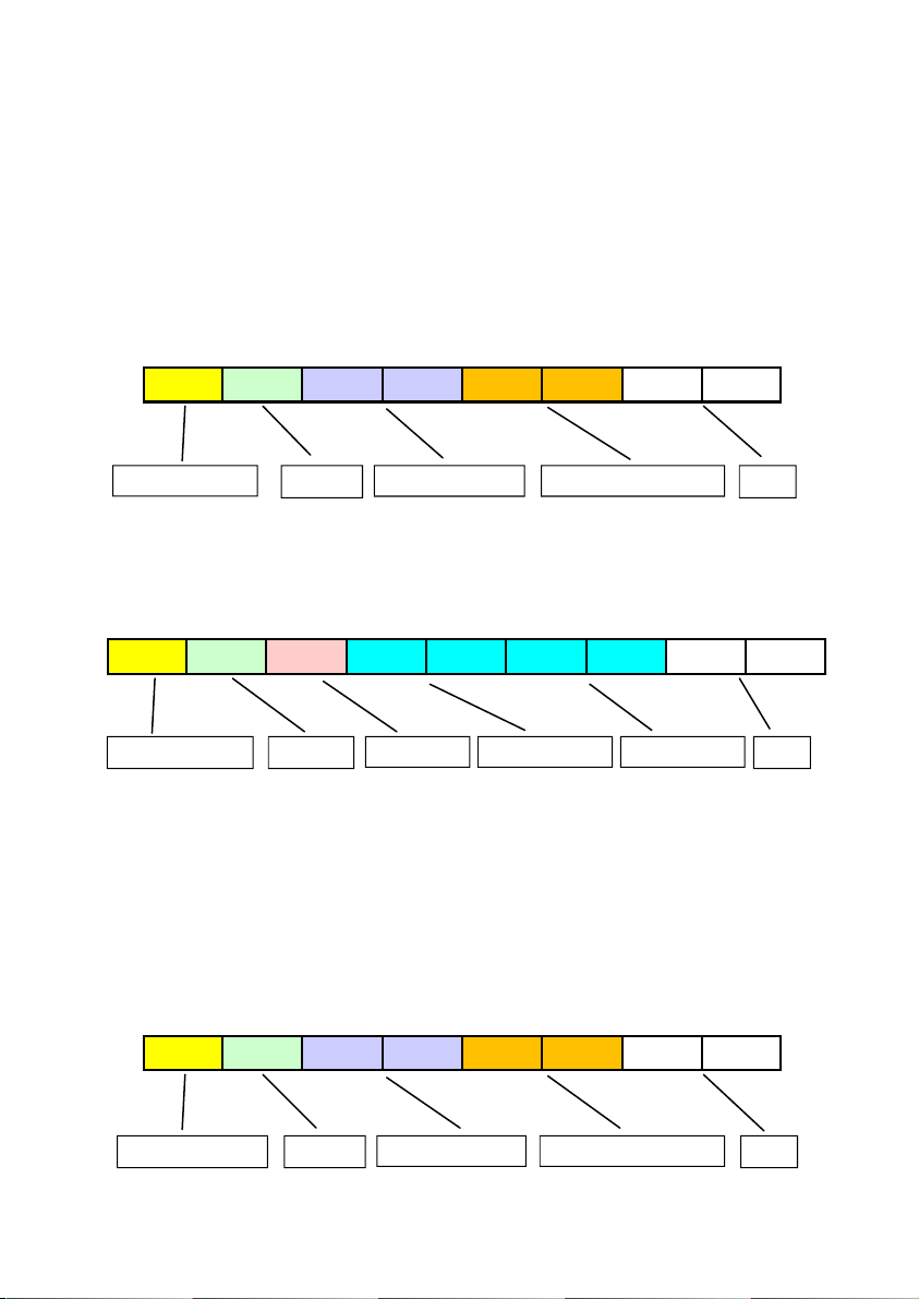
Example 1: Flow rate reading
Master requests the slave number 0x01 (MX4B converter) a flow rate.
Slave ID: 0x01
Function: 0x04 (Read input registers)
Initial address: 0x2000
Number of registers to read: 2
01 04 20 00 00 02 7A 0B
Function
The slave responds after more than 3.5 characters, indicating its identification, the
requested function code, the number of data bytes to be sent, data and the CRC.
01 04 04 44 AB 6C 91 38 72
Function
The flow rate received is the floating point 32 bits data 0x44AB6C91 = 1371,31
Example 2: Totalizer reading
Master requests the slave number 0x01 (MX4B converter) the totalizer value.
Slave ID: 0x01
Function: 0x03 (Read holding registers)
Initial address: 0x3000
Number of registers to read: 2
01 03 30 00 00 02 CB 0B
Register address N. of registers to read Slave ID (MX4B)
N. of bytes Flow rate LSB Flow rate MSB
CRC
CRC Slave ID (MX4B)
Register address N. of registers to read Slave ID (MX4B) CRC Function
10
Page 11
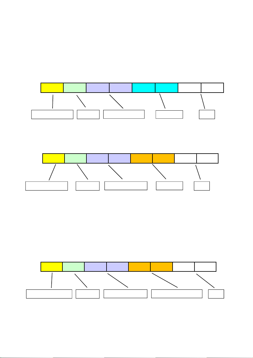
The slave responds after more than 3.5 characters, indicating its identification, the
requested function code, the number of data bytes to be sent, data and the CRC.
01 03 04 42 F2 08 FD F9 89
Slave ID (MX4B)
The totalizer value is the floating point data 0x42F208FD = 121,017555
Exemple 3. Writing the Flow rate value for 20 mA
Master requests slave number 0x01 (MX4B converter) to write the contents
corresponding to Flow rate 20 mA. The value to write is 1400.
Slave ID: 0x01
Function: 0x10 (Write multiple registers)
Initial address: 0x3004
Number of registers to write: 2
Data to write: 1400 = 0x44AF0000
01 10 30 AF 00 00 82 8C 04 00 02 04 44
Slave ID
(MX4B)
Function Register
The slave responds after more than 3.5 characters, indicating its identification, the
requested function code, the register address, the number of registers, the number of
written data bytes, data and the CRC.
Function
address
N. de bytes Total LSB Total MSB
N.
registers
N.
bytes
20mA
MSB
20mA
LSB
CRC
CRC
01 10 30 04 00 02 0F 09
Register address N. of written registers Slave ID (MX4B) CRC Function
11
Page 12
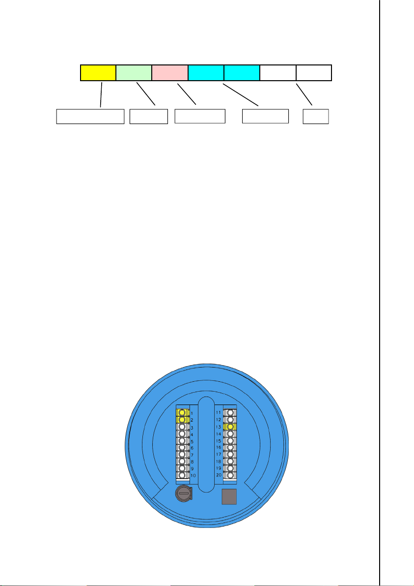
Example 4. Writing totalizer units.
Master requests slave number 0x01 (MX4B converter) to write the corresponding code to
totalizer units. The value to write is 0x03 (liters).
Slave ID: 0x01
Function: 0x06 (Write Single register)
Initial address: 0x3006
Data to write: 3 = 0x0003
01 06 30 06 00 03 26 CA
Slave ID (MX4B) CRC Function
The slave responds after more than 3.5 characters, indicating its identification, the
requested function code, the register address, written data and the CRC.
01 06 30 06 00 03 26 CA
Example 5. Read flow rate units
Master requests slave number 0x01 (MX4B converter) to read the corresponding code to
flow rate units.
Slave ID: 0x01
Function: 0x03 (Read Holding registers)
Initial address: 0x3007
Number of registers to read: 1
01 03 30 07 00 01 3A CB
Register address
Register address Units code Slave ID (MX4B) CRC Function
Units code
Register address N. of registers to read Slave ID (MX4B) CRC Function
12
Page 13
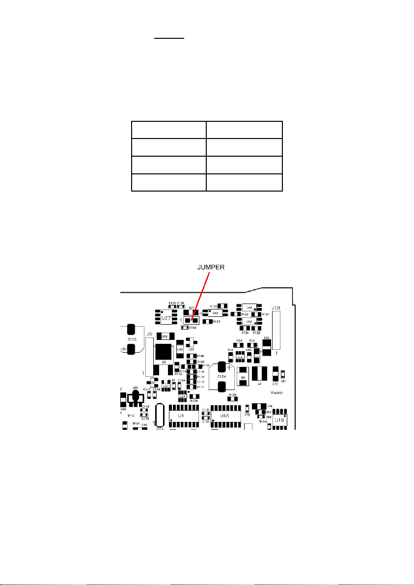
The slave responds after more than 3.5 characters, indicating its identification, the
requested function code, the number data bytes, read data and the CRC.
01 03 02 00 07 F9 86
N. de bytes Units code Slave ID (MX4B) CRC Function
The received code in the example is 0x0007 that corresponds to l/h.
7 ELECTRICAL CONNECTION
For the electrical connection, the MX4 converter has two terminal strips. To help in the
wiring of the equipment, the description of the terminals is marked on a label in the rear
cover of the device.
For the electrical connection it is recommended to use multiple conductor cables with
individual cable sections in the order of 0.25 to 0.5 mm
Before starting the installation, check that the cable glands are the right size for the
cables to be used. This will guarantee the instrument will stay watertight. The cable
glands used are for cables with outside diameters between 3.5 mm and 10 mm.
To connect the cables, peel the outside insulation to free the inner cables. It is
recommended to put a terminal at the ends of the wires to avoid loose ends. Pass the
cables through the cable glands and screw down in the corresponding positions of the
terminal strip. Once the wiring is finished make sure that the cables are well gripped by
the cable glands to maintain the degree of protection.
Incorrect installation of the cable gland or inadequate cable placement can cause
irreparable damage to the converter.
The recommended cable is a three wire cable with a shield. These cables should have a
characteristic impedance of 120 .
2
.
13
Page 14
Terminal
1 B
2 A
13 GND
It is recommended that the shield is connected to ground only in one of its ends.
The cable connection between the MX4B converter and a Master is the following:
MX4B Converter Master
Terminal A A/D-
Terminal B B/D+
GND G/Reference
In some cases in which several devices are connected in a line it is necessary to incorporate
an impedance at the end. If the converter MX4B is the last device of the line, the impedance
can be set by placing a jumper in the position shown in the figure below.
14
Page 15
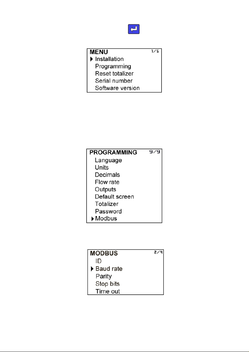
8 CONVERTER PROGRAMMING
Turn on the converter and press (Enter)
screen appears:
With the keys (Down / Left) and (Up), select Programming, and then validate with the key
(Enter).
To access the programming of the converter, you must enter the password. At first
access, the default password is 0123. For more details about the password, see the
instructions manual of the instrument (R-MI-FIMX4 or R-MI-FAMX4).
Once the password is entered, the first screen allows to choose between the different
programming options.
to go to the main menu. The following
Go to the Modbus option and press (Enter). It appears the screen that allows to program
the communication parameters.
15
Page 16
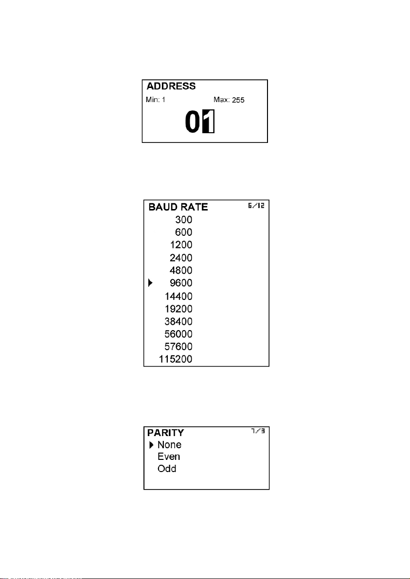
8.1 Slave address
In this screen the slave address can be assigned to the converter. This address must be
unique, that is, no other slave devices in the bus can have the same number.
8.2 Baud rate
It determines the data transmission speed. All the devices in the bus have to be
configured with the same baud rate.
8.3 Parity
It is used to detect communication errors. All the devices in the bus have to be configured
with the same parity .
8.4 Stop bits
It allows to choose the number of stop bits. All the devices in the bus have to be
configured with the same number of stop bits.
16
Page 17
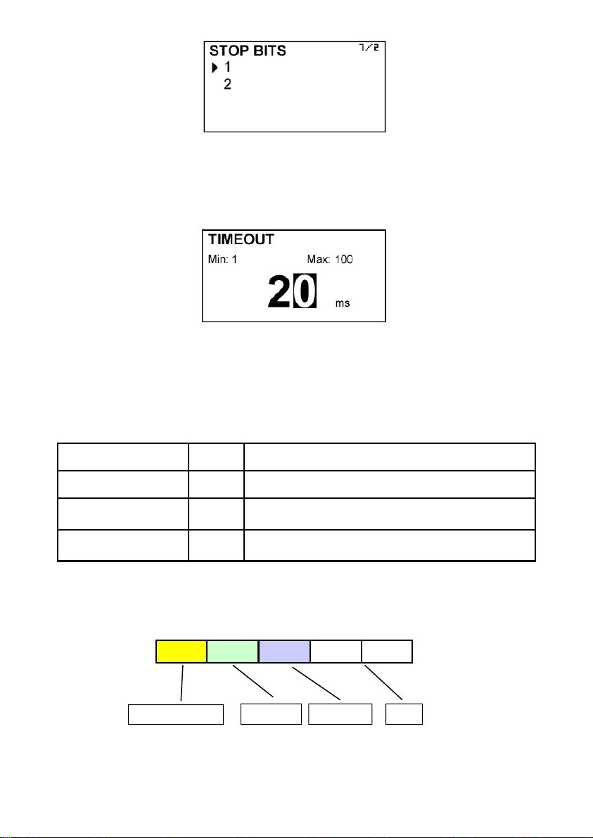
8.5 Timeout
It is the minimum time between frames. Default value is 20 ms. In this screen a different
value can be programmed, taking into account that it must be at least the time
corresponding to 3.5 characters. If a lower value is intended to be programmed, the
converter will limit internally the timeout to that value.
Once the previous steps are done, a communication with a master can be established.
9 ERRORS
MX4B converter can report errors when transmitting or receiving processes.
The implemented errors in the converter are the following:
Error
Function not
implemented
Wrong data address 0x02
Wrong data value 0x03
When any of these errors is detected, MX4B converter responds with a frame with the
following structure:
Slave ID (MX4B)
* The function is the same as sent by the master, changing the first bit from 0 to 1.
In the example the function sent by the master was 07 and the converter responds with
code 01 (function not implemented).
Code
(Hex)
0x01
01 87 01 7A 0B
The function requested by the master is not
implemented by the MX4B converter
The register intended to be accessed (read or write) is
beyond the limits allowed by the converter
The value contained in the data field is not allowed by
the converter.
Function *
Error code CRC
17
Description
Page 18

HART
1 INTRODUCTION
HART is a bi-directional communication protocol that provides data access between
intelligent field instruments and host systems. A host system can be any software
application from a handheld terminal to control plant processes, asset manager, safety or
other system using any control platform.
HART protocol is based on a current loop, and has the peculiarity that provides two
simultaneous communication channels, the analog signal of 4-20 mA and digital signal.
Signal 4 to 20 mA communicates the primary measured value (in the case of a field
instrument) using the 4-20 mA current loop.
Additional device information can be transmitted by a digital signal superimposed on the
analog signal.
MX4H Converter is a field instrument that meets the HART protocol revision 6.0.
This document specifies all the functions implemented MX4H regarding the protocol
converter.
MX4H Converter is fully compatible with the HART Server software from HART
Communication Foundation.
Tecfluid S.A. do not guarantee that the MX4H converter is compatible with the different
servers on the market.
2 DEVICE IDENTIFICATION
Manufacturer: Tecfluid S.A.
Model: Converter MX4H
Manufacturer identification
code: 204 (0xCC)
Device code: 141 (0x8D)
HART revision 6.0
Number of device variables: 2
Physical layer supported: FSK
Device category: Transmitter
3 DESCRIPTION OF LOOP CURRENT
There is one current loop.
The current output is related directly to the measured flow rate of the process input, which
in turn is the primary variable (PV).
The output range is from 4 mA to 20 mA for full scale output.
The maximum current drawn is 20 mA at and above 100 % of full scale.
The Multi-Drop (loop disabled) current is 4 mA.
The receive impedance is Rx > 8,5 M and Cx < 200 pF
18
Page 19
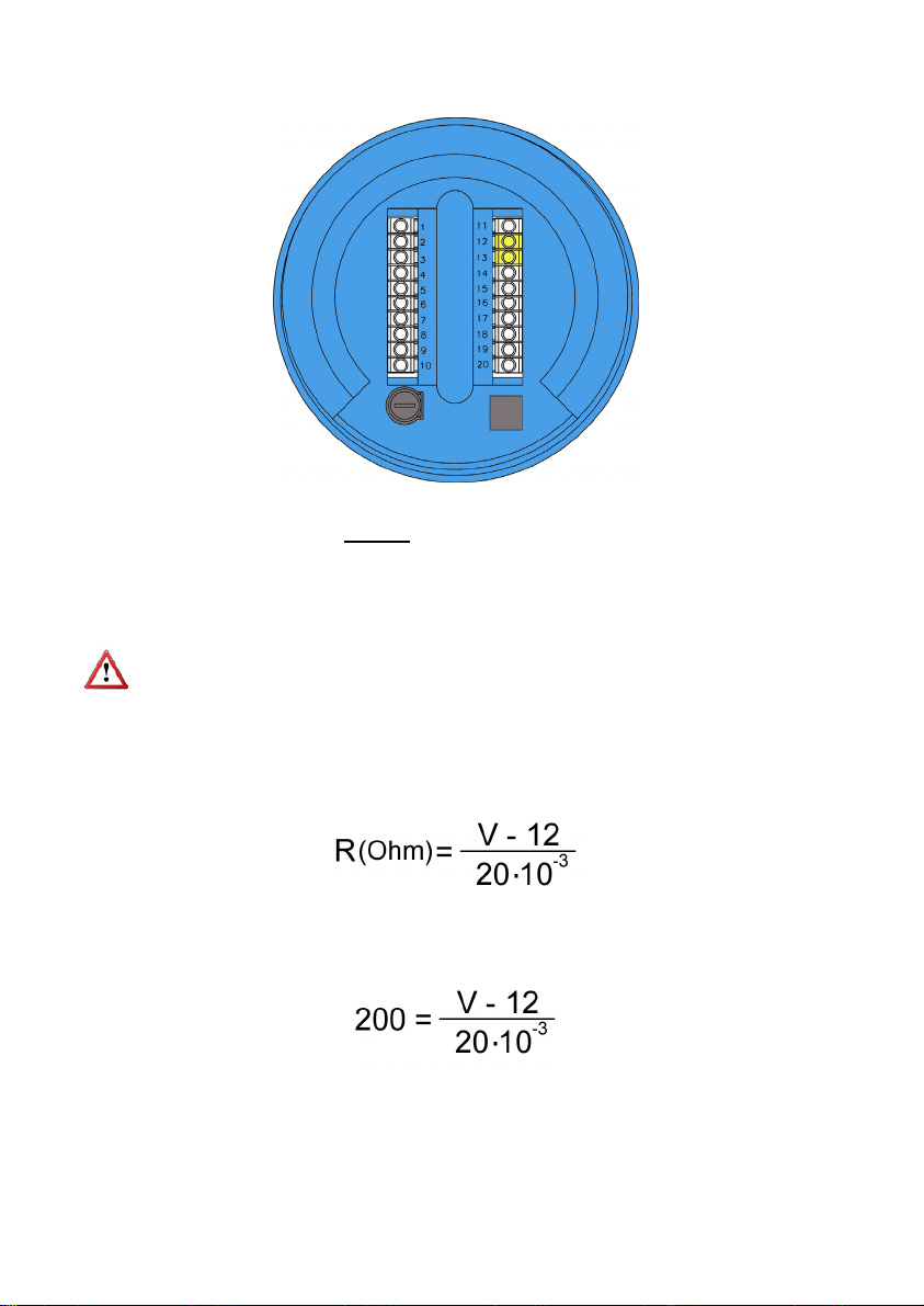
3.1 Current loop connection
Terminal
12 mA (+)
13 mA (-)
The mA output is galvanically isolated.
NOTE: The analog output incorporates a protection against polarity inversion. Due to a
second overvoltage protection, if a power supply voltage higher than 32 V is connected,
the converter could be damaged.
In the case of a HART transmitter, an external resistor (R) must be included. Its minimum
value will be 200 , and the maximum value will depend on the current loop power
supply.
Therefore, the minimum operating voltage will be V = 16 V.
This value is calculated without taking into account the resistance of the cable.
This resistance will depend on each cable type and length, and must be added to the load
resistor to calculate the minimum operating voltage of the system.
19
Page 20
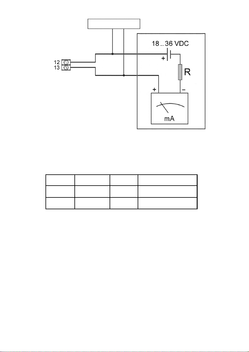
Modem HART
Analog output
4 VARIABLES
4.1 Device variables
The MX4H converter has 2 device variables:
Connection diagram
Number Classification Name Units code
0 66 Flow rate
1 68
4.2 Dynamic variables
There is only one dynamic variable in the device. This is the flow rate and it is associated
to the loop current.
Totalized
volume
16, 17, 18, 19, 22, 24, 28,
30, 131, 136, 137, 138
40, 41, 42, 43
5 COMMANDS
5.1 Universal commands
All universal commands are available. Commands with some points to take into account
are:
Command 3. It returns the “Primary variable” with 9 data bytes in the response.
Command 14. Returns the following frame:
“0x00, 0x00, 0x00, PV units code, 0x7F, 0xA0, 0x00, 0x00, 0x7F, 0xA0, 0x00, 0x00, 0x7F,
0xA0, 0x00, 0x00”
This frame indicates the master that the MX4H converter has not transducer information
implemented.
20
Page 21

Command 15. Returns PV units code in byte 2. Internally, Upper and Lower Range units
are the same as Primary Variable units.
Command 18. It can return a response code 9 “Invalid Date Code”. The date code is
filtered, “day” byte must be in the range from 1 to 31 both inclusive and “month” byte must
be between 1 and 12 both inclusive.
Command 48. Returns 8 data bytes. Specific Device Status bytes are the following:
Field Device
Status bits set
0x10
0x10
Field Device
Status bits set
Byte Bit Meaning Class
This bit is set when a configuration data error
is detected on a cold start or reset of the
0x01
0 0x02
0x04
Bits not mentioned are not used and are always reset to “0”.
For byte 0, bits 0x01, 0x02 & 0x04 resets when command 48 is answered. Bit 0x80 is
reset when all bits from byte 1 are 0.
Byte Bit Meaning Class
1 0x20
device and the configuration data has been
recovered from block 1 of data memory
This bit is set when a configuration data error
is detected on a cold start or reset of the
device and the configuration data has been
recovered from block 2 of data memory
This bit is set when a configuration data error
is detected on a cold start or reset of the
device and the configuration data has been
recovered from block 3 of data memory
0x80 Default values have been loaded into memory Error 0xE0
Lower range has not been
0x10
configured
Upper range has not been
configured
Flow rate (PV) units have not
0x40
been configured
Warning 35 0x80
Warning 35 0x80
Warning 44 0x10
Warning 0x10
Warning
Warning
Commands
that can reset
the bit
The three bits in byte 1 are set when a configuration data error is detected on a cold start
or reset of the device. Each bit is reset when the corresponding data is accessed by a
write command or manually by the operator.
Byte Bit Meaning Class
Polling Address has not been
0x40
2
In byte 2, bits 0x40 and 0x80 cannot be reset manually by the operator
Bytes 3, 4 & 5 of Device Specific Status are not used and all their bits will be reset “0”.
configured
0x80 Tag has not been configured Warning 18 0x10
Warning 6 0x10
21
Commands
that can reset
the bit
Field Device
Status bits set
Page 22

5.2 Common practice commands
Command implemented are the following:
Number Command
33 Read Device Variables
34 Write Primary Variable Range Values
35 Write Primary variable Damping Values
38 Reset Configuration Changed flag
40 Enter/Exit Fixed Current Mode
44 Write Primary Variable Units
48 Read additional device status
6 BURST MODE
MX4H converter does not support Burst Mode.
7 OPERATING MODES
The converter MX4H implements fixed current mode.
To change to this mode Command 40 can be used.
The output current can be set to any fixed value between 4 mA and 20 mA.
By sending Command 40 to the MX4H with a value of “0” the fixed current mode will be
exited.
This mode is automatically exited on a device reset or power up.
Current signalling can be disabled using Command 6. In this case the current output will
be set to 4 mA.
Current signalling is normally disabled when the converter is part of a network coexisting
with other instruments.
When current signalling is disabled using the “Loop Current Mode = 0” in Command 6, the
only way in which current signalling can be enabled is through the use of Command 6 and
setting “Loop Current Mode = 1”.
If there is a power up, current signalling keeps this operating mode.
8 WRITE PROTECTION
Write protection is provided, selected by an internal jumper.
When the jumper is present, all commands are accepted. When the jumper is absent, no
write commands or local configuration changes are accepted.
22
Page 23

Resume of the main communication characteristics:
Manufacturer, Model and Revision Tecfluid S.A., converter MX4H, Rev. 0
Device type Transmitter
HART revisión 6.0
Device Description available No
Number and type of sensors 1, exterior
Number and type of actuators 0
Number and type of host side signals 1, 4 – 20 mA analog
Number of Device Variables 2
Number of Dynamic Variables 1
Mappable Dynamic Variables No
Number of Common Practice Commands 7
Number of Device Specific Commands 0
Bits of Additional Device Status 9
Burst mode? No
Write Protection? Yes
HART® is a registered trade mark of HART Communication Foundation.
23
Page 24

WARRANTY
Tecfluid S.A. guarantees all the products for a period of 24 months from their sale, against all faulty
materials, manufacturing or performance. This warranty does not cover failures which might be
imputed to misuse, use in an application different to that specified in the order, the result of service
or modification carried out by personnel not authorized by Tecfluid S.A., wrong handling or
accident.
This warranty is limited to cover the replacement or repair of the defective parts which have not
damaged due to misuse, being excluded all responsibility due to any other damage or the effects
of wear caused by the normal use of the devices.
Any consignment of devices for repair must observe a procedure which can be consulted in the
website www.tecfluid.com, “After-Sales” section.
All materials sent to our factory must be correctly packaged, clean and completely exempt of any
liquid, grease or toxic substances.
The devices sent for repair must enclose the corresponding form, which can be filled in via website
from the same “After-Sales” section.
Warranty for repaired or replaced components applies 6 months from repair or replacement date.
Anyway, the warranty period will last at least until the initial supply warranty period is over.
TRANSPORTATION
All consignments from the Buyer to the Seller´s installations for their credit, repair or replacement
must always be done at freight cost paid unless previous agreement.
The Seller will not accept any responsibility for possible damages caused on the devices during
transportation.
24
 Loading...