

Page 1
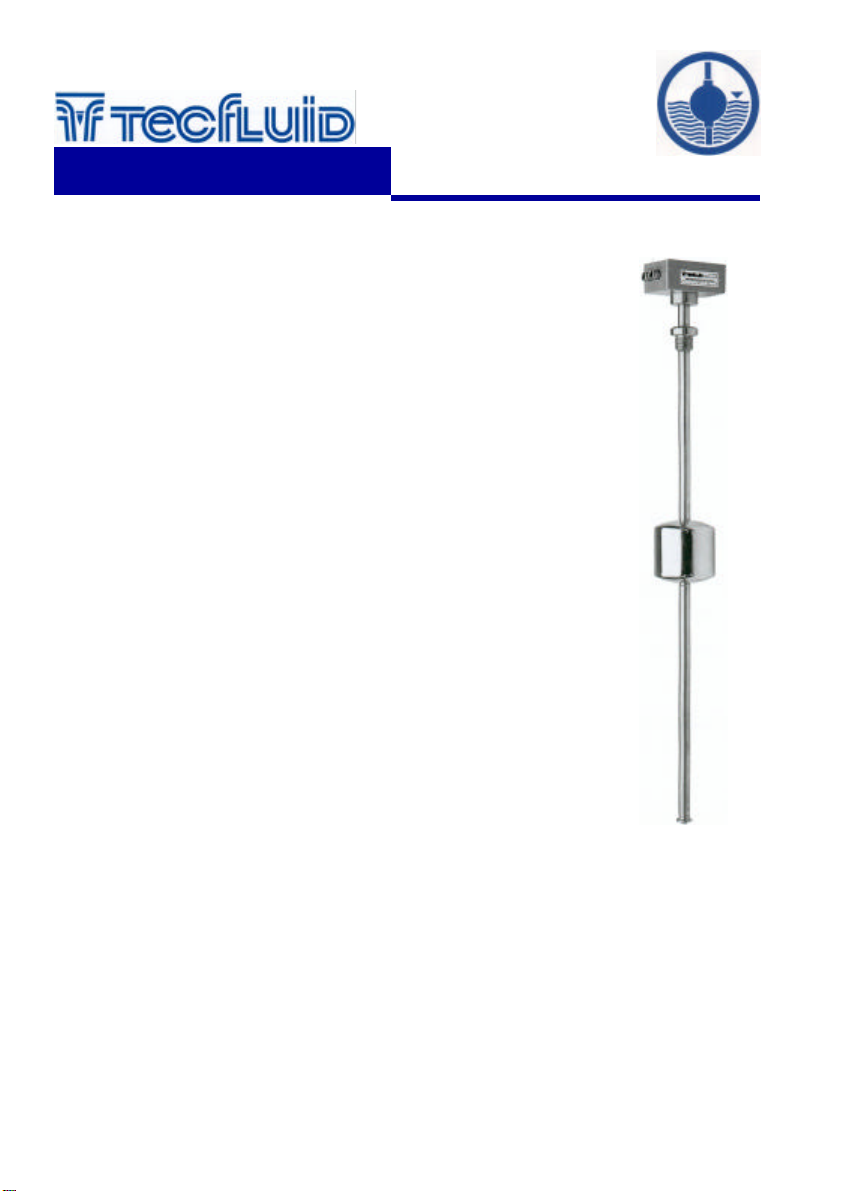
Float Level Switch
English Version
Series
instrumentation
for fluids
LC-30 / LC-31 / LC-M11 / LC-M12
User’s Manual
RECEPTION
Check that the level instrument is mechanically correct by means of the
following inspection:
− The float (4) slides smoothly along the rod (3) (do it carefully by hand
in moving the float up and down).
− The rod (3) does not have any shock and is not bent.
− The bottom float stop (7) at the rod is in place.
Check with a multimeter that when the float slides along the rod, the
reed switch is activated in changing the output from NO to NC or vice
versa (depending on the wiring according to attached diagram).
Check that the switching points correspond to the required ones.
Check that the float density is inferior than the density of the liquid and
that the float is in the correct position (the mark UP engraved at the top
of the float indicates that this side of the float must be up).
INSTALLATION
The mounting of the level switch is vertical. The float level varies
accordingly with the level of the liquid.
Mount the seal on the flange or the coupling thread.
Introduce with care the float through the mounting hole until the flange
or coupling thread couples with the tank. Fix the flange with the
appropriate nuts & bolts.
You could mount, if the installation so require, the float by the inside of
the tank, in removing the bottom float stop (7).
In the case of a coupling thread, turn until tight. Do not apply torques
greater than 60 Nm.
REED SWITCHES
The LC’s series has two types of contacts for
level indication, RSC and Bi-stable RBC. The
difference is in the status of the contact once
the float has passed the contact.
Series RSC
The RSC is a reed switch without “memory”. It
is only activated in presence of the magnetic
field of the float. If the float moves away from
position of the switch, the switch returns to it’s
non-active position, which is the same for the
float being above or below the switch.
This system provides an indication of when the
level is at the same position as the reed switch
but will not provide an indication of the level
away from this point. That is, it provides an
indication of actual level but not high or low
level.
Series Bi-stable RBC
The bi-stable RBC reed switch remains in it’s
switched position after the float has passed. It
will remain in one position when the float is
below and remains in the opposite position
while the float is above the reed switch. This
provides a High/Low indication but not indicate
the exact position of the level.
C-MI-LC30 Rev.: 0
Page 2
Technical Data
• Mounting: Vertical.
• Connection: DN-40 PN-16 DIN 2501 Flange.
R 1½” BSP thead.
(Others available on request).
• Maximum length: AISI-316 ... 6000 mm.
PVC, PTFE ... 2500 mm.
PVC, PTFE ... 6000 mm
(internal AISI-316).
• Precision: ± 2 mm.
• Hysteresis: ± 4 mm.
• Working pressure:
PN-16 AISI-316.
PVC, PTFE with internal AISI-316 tube.
PN-10 PVC, PTFE.
• Liquid temperature:
-20ºC...+150ºC en AISI-316, PTFE.
0ºC...+50ºC PVC.
• Ambient temperature:
-20ºC...+60ºC AISI-316, PTFE.
0ºC...+50ºC PVC.
• Liquid density: From 0,45 to 3 kg/l.
• Liquid viscosity: Maximum 1500 cSt.
• Contacts: Reed 1 A 220 V.
(maximum 9 with minimum separation
of 20 mm)
Conforms with Directive 73 / 23 / CEE
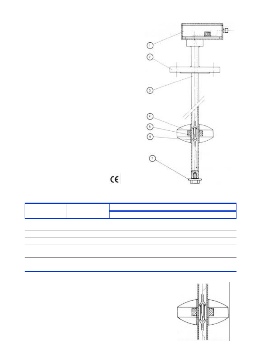
CONSTRUCTION
No. Piece Materials
1 Enclosure
2 Connection AISI-316 PVC PTFE
3 Rod AISI-316 PVC PTFE
4 Float AISI-316 PVC PTFE
5 Magnet Alnico Alnico Alnico
6 Reed switch - - 7 Float stop AISI-316 PVC PTFE
LC-.../INOX LC-.../PVC LC-.../PTFE
DIN 43650/
Aluminium
OPERATION
Inside the guide tube, reed switches are mounted at the
alarm/control points..
As the float passes the position where a reed switch is
located, the magnetic field from the float actives the switch.
The maximum number of alarm or control points is 9.
2
DIN 43650/
Aluminium
DIN 43650/
Aluminium
Page 3
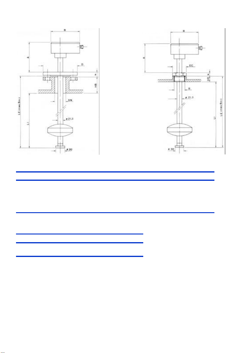
DIMENSIONS
LC-30 LC-31
LC-30
DN PN D k g Lxno. b A B HB LE LI
25* 40 115 85 68 14x4 18 160 125
40 16 150 110 88 18x4 18 160 125
100* 16 220 180 158 18x8 20 160 125
Related to the
individual measuring
range.
150* 16 285 240 212 23x8 22 160 125
( * on request )
LC-31
R EC b A B HR LE LI
1 ½” 60 22 160 125 30 Related to
range
WIRING
The wiring should be made according to the attached diagram.
When using inductive loads, such as relays or electro-valve coils, surge arresters should be
installed to protect the reed contacts.
With a dc supply, a diode should be used.
For an ac supply, an RC circuit can be used as shown, although a varistor (VDR) is better and is
easier to select the right value.
The VDR should have a breakdown voltage greater than 1.5 times the rms voltage.
The standard varistor ratings specify the rms working voltage for the varistor, for example a
S05K25 varistor will be for 25 V
working and will have a breakdown voltage of 39 V at 1 mA.
rms
3
Page 4
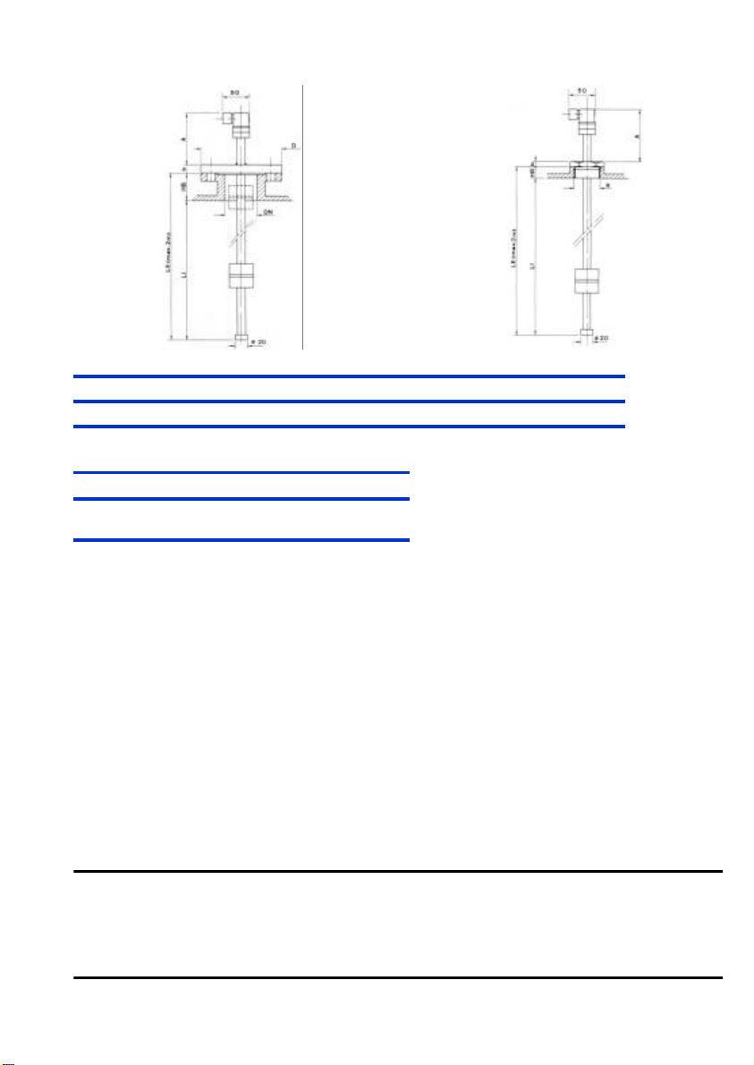
DIMENSIONS
LC-M12 LC-M11
LC-M12
DN PN D k g Lxno. b A HB LE LI
25 16 115 85 68 14x4 18 100 Related to range
LC-M11
R EC b A HR LE LI
1 ½” 60 22 100 30 Related to
range
WARRANTY
Tecfluid S.A. GUARANTEES ALL ITS PRODUCTS FOR A PERIOD OF 12 MONTHS, maximum 18
months after consignment, against all defects in materials and workmanship.
This warranty does not cover failures which can be imputed to misuse, use in an application different
to that specified in the order, the result of service or modification by un-authorized persons, bad
handling or accident.
This warranty is limited to cover the repair or replacement defective parts which have not been
damaged by misuse.
This warranty is limited to the repair of the equipment and all further and eventually following damages
are not covered by this warranty.
In the event of consignment of equipment to our factory, this should be done with the equipment well
packed and prepaid transport, clean of any liquids, grease or hazardous materials. Tecfluid S.A. will
not accept any responsibility for damage done during transport. Together with the equipment, a note
should be enclosed indicating the failure observed, the name, address and telephone number of the
sender.
TECFLUID, S.A.
Narcís Monturiol, 33
TECFLUID, S.A.
E-08960 Sant Just Desvern
Narcís Monturiol, 33
Tel. + 34 93 3724511 - Fax + 34 93 4734449
E - 08960 Sant Just Desvern
E-mail: [email protected]
Internet: www.tecfluid.com
Tel. + 34 93 3724511 - Fax + 34 93 4730854
TECFLUID, S.A. reserves the right to modify the above specifications without notice.
Las diferentes formas y medidas de los aparatos descritos en este folleto, pueden ser modificadas, sin previo aviso, si las innova-
ciones técnicas en nuestros procesos de fabricación lo requieren.
 Loading...