

Page 1
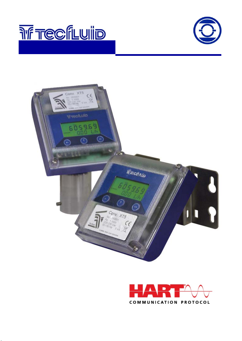
XT5 /XT5H
Converter for
Flomid/Flomat
instrumentation
for fluids
Sensors
Instructions Manual
R-MI-XT5 Rev.: 2 English version
Page 2

INDICE
1. INTRODUCTION ..................................................................................... 4
2. ELECTRICAL CONNECTON ................................................................. 4
2.1. Power supply connection ......................................................... 5
2.2. Analog output connection ........................................................ 5
2.3. Pulse output connection ........................................................... 8
2.4. Connection examples ............................................................... 8
2.5. Sensor connection ..................................................................... 9
3. OPERATION ........................................................................................... 10
3.1. Configuration of the flow rate calculation parameters ............ 10
3.1.1 Sensor factor ............................................................... 10
3.1.2 Electronics factor ....................................................... 10
3.1.3 Nominal diameter ....................................................... 11
3.1.4 Measuring units .......................................................... 11
3.1.5 Mains frequency ......................................................... 11
3.2. Configuration of the rest of parameters .................................. 12
3.2.1 Decimals ..................................................................... 12
3.2.2 Current output ............................................................ 12
3.2.3 Pulse output ............................................................... 13
3.2.4 Cut off .......................................................................... 13
3.2.5 Damping ..................................................................... 13
3.2.6 Flow rate direction .....................................................
3.2.7 Empty pipe detection ................................................. 15
3.3. Zero offset adjustment .............................................................. 15
3.4. Visualization of the serial number and software version ...... 16
3.5. Empty pipe indication ......................…………………………..... 16
3.6. Reset ……………………………………………………………........ 16
14
4. KEYBOARD DISABLE AND ”WRITE PROTECT” ……..………............ 16
5. CHANGING THE POSITION OF THE DISPLAY ...………..…............... 16
TM
6. HART
COMMUNICATION................................................................... 16
2
Page 3

7. MAINTENANCE ….................................................................................... 18
7.1. Fuse ……………………………..……………………………............ 18
8. EX AMPLES OF USEFUL CALCULATIONS .......................................... 18
8.1. Measurement error correction …………………….…………....... 18
8.2. Configuration of pulses / unit of volume .....................…........ 18
9. TECHNICAL CHARACTERISTICS ......................................................... 19
9.1. Power supply .............................................................................. 19
9.2 Analog output ............................................................................. 19
9.3 Pulse output ................................................................................ 19
9.4 Totalizer ....................................................................................... 19
9.5 Flow rate indication .................................................................... 19
9.6 General characteristics .............................................................. 19
9.7 Elect. charact. referred to the analog loop and comm. …....... 19
10. DIMENSIONS …………..………............................................................... 20
11. TROUBLESHOOTING ……..................................................................... 21
12. PROGRAMMING DIAGRAM ……........................................................... 22
3
Page 4

1 INTRODUCTION
The XT5 converter is an electronic equipment that adapts to the Flomid and Flomat series
electromagnetic flow sensors. The microprocessed electronic circuit offers the following
benefits:
Excitation of the coils by means of pulsed signal to obtain a minimal zero offset.
Pulse and analog current outputs proportional to the flow rate and user
configurable.
Local and separate mounting.
Easy interchangeability with other sensors.
Display orientable 180º to adapt to the installation position.
HART
TM
protocol compatibility (XT5H model).
2 ELECTRICAL CONNECTION
For the electrical connection, the XT5 has a screw terminal strip.
For the electrical installation it is recommended to use multiple conductor cables with
individual cable sections in the order of 0.25 to 0.5 mm
2
in order to make it easier to
connect. It is better to maintain the cables with mains voltage (power supply) separated
from the cables with low level signals (4-20 mA etc.).
Before starting the installation, check that the cable glands are the right size for the cables
to be used, this will guarantee the instrument will stay watertight. The PG 11 cable glands
used are for cables with outside diameters between 6 mm and 10 mm.
Peel the outside insulation to free the inner cables. It is recommended to tin the ends of
the wires to avoid loose ends. Pass the cables through the cable glands and screw down
in the corresponding positions of the terminal strip. Once the wiring is finished make sure
that the cables are well gripped by the cable glands to maintain the degree of protection.
IMPORTANT NOTE: In order to comply with the electrical safety requirements as per EN61010-1 (IEC 1010-1), the installation of the equipment must take into account the
following:
A mains switch must be provided to disconnect the equipment. This switch must
be marked as the disconnecting device for the equipment and be within easy
reach of the operator.
The mains supply must have an earth line.
The housing must not be opened when the instrument has mains supply
connected.
Before starting to install the equipment, check that the supply voltage available is the
same as marked on the label of the instrument.
To help in the connecting of the equipment, the description of the terminals is marked on
the printed circuit next to the terminal strip.
4
Page 5
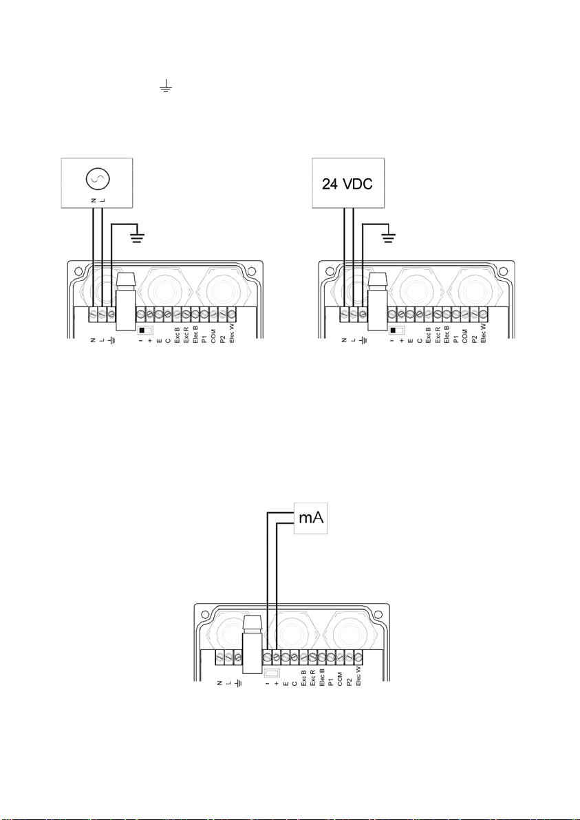
2.1 Power supply connection
Terminal AC Power supply DC Power supply
Earth Earth
N Neutral 0 V (-)
L Phase 24 V (+)
It is important to connect the mains earth to the instruments with AC power supply due to
the presence of a mains filter inside that requires this connection.
2.2 Analog output connection
Terminal
+ mA (positive).
- mA (negative).
The analog output can be either active (that means the receptor must be passive) or
passive (that means the receptor must supply the power for the current loop). It is
recommended to use a receptor with an input resistance of less than 700 Ω to guarantee
correct operation.
5
Page 6
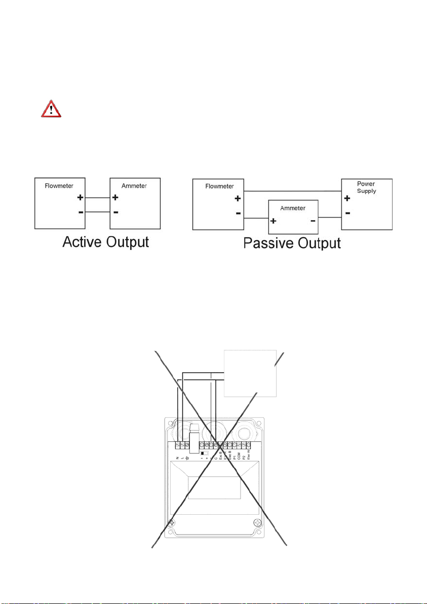
To configure the analog output type (active or passive) there is a slide switch situated just
behind the terminal strip. For the passive mode the switch must be towards the positive
terminal and for active mode the switch must be towards the negative terminal. To move
the switch use the point of a small screwdriver.
In the case of using HART communication the output mode should be passive. Normally a
HART master is active.
NOTE: The analog output has protection against reversed polarity. Due to another
protection against over voltages, if a loop supply voltage of greater than 32 V is connected
the equipment may be damaged.
Possibilities of connection for the power supply and analog output
Passive output
Active
indicator
e. g. PLC
6
Page 7
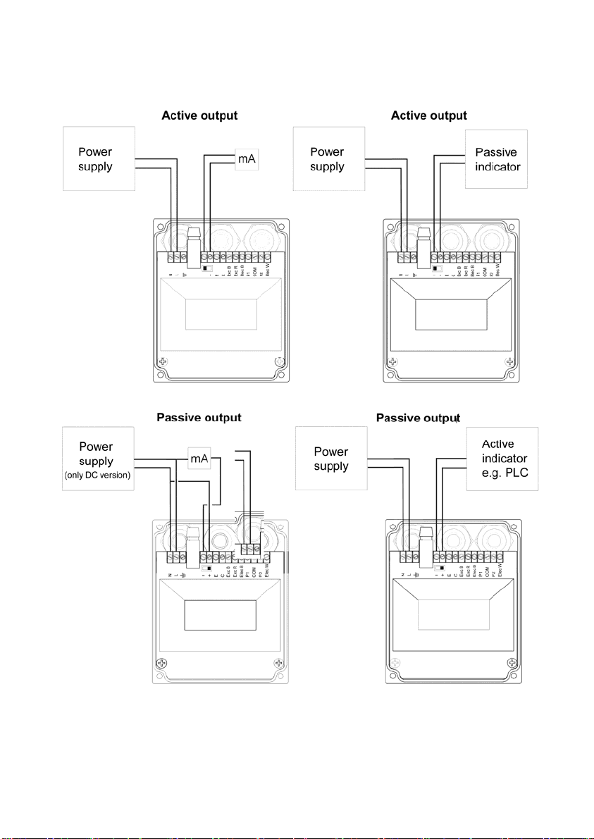
mA: Ammeter
7
Page 8
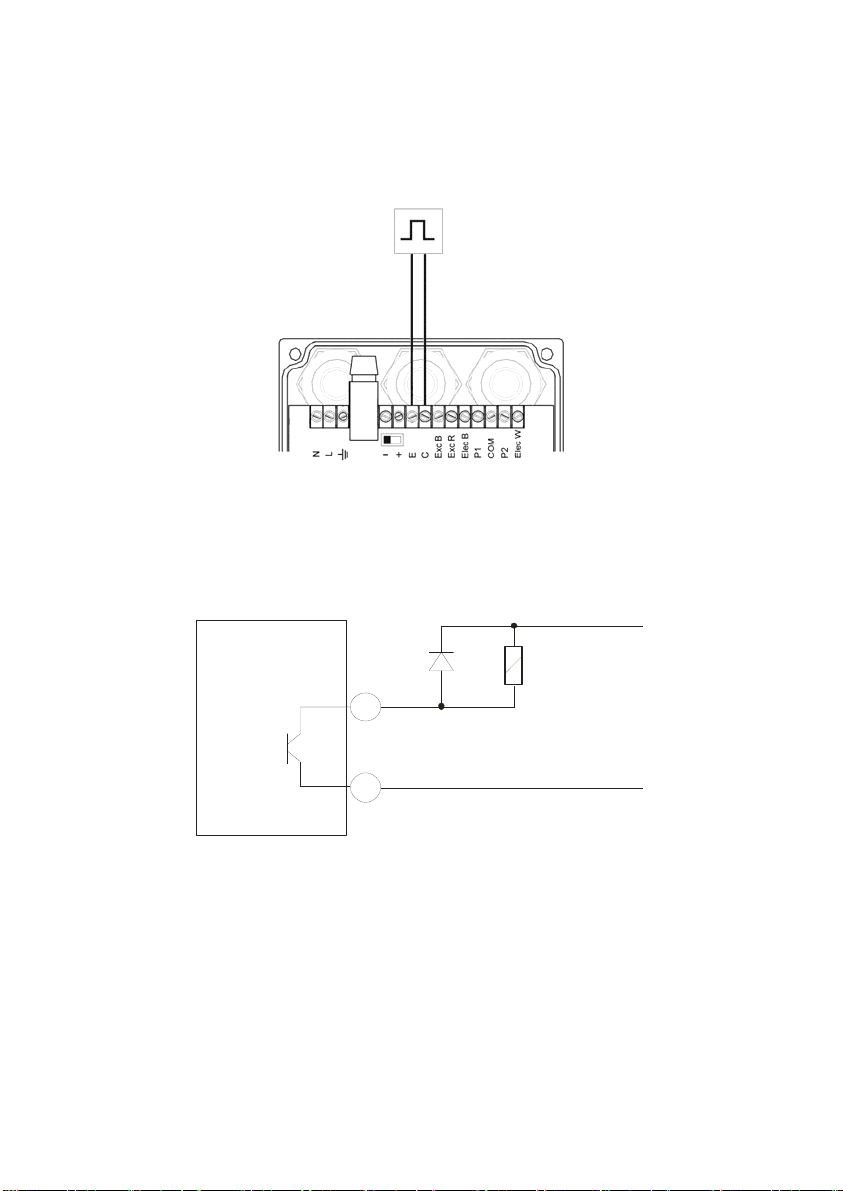
2.3 Pulse output connection
Terminal
E Emitter.
C Collector.
The pulse output is opto-isolated. The terminals are the collector and emitter of an NPN
bipolar transistor. Optionally this output can be supplied for AC loads (see 9.3).
In the case of using inductive loads, in order to protect the output transistor, the use of
free wheeling diodes is required.
XT5
Co i l
C
E
2.4 Connection examples
The two usual ways to connect the alarm outputs are NPN or PNP modes, depending on if
the load is connected to the positive or negative terminal.
In the following figures, an example of connection for the alarm 2 in NPN and PNP mode can
be seen.
8
Page 9
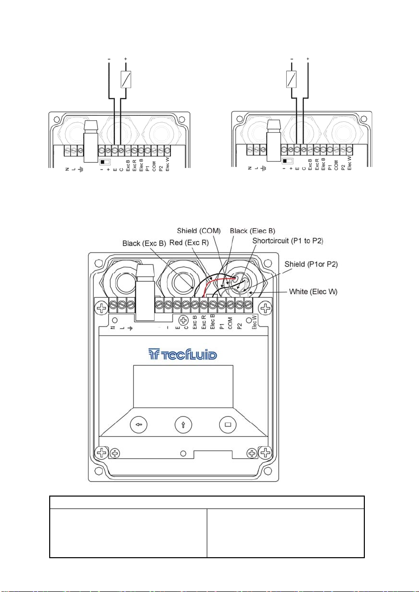
NPN connection
LOAD LOAD
2.5 Sensor connection
When the electronics is mounted separate from the sensor, the interconnection is made
through a cable gland. The terminals are the following:
PNP connection
Terminal
Exc B Top Coil (Black cable) Elec B Front electrode (black cable)
Exc R Bottom coil (red cable)
COM Process earth (overall bried) P2 Rear electrode (braid)
P1 Front electrode shield (braid)
Elec W Rear electrode (white cable)
9
Page 10
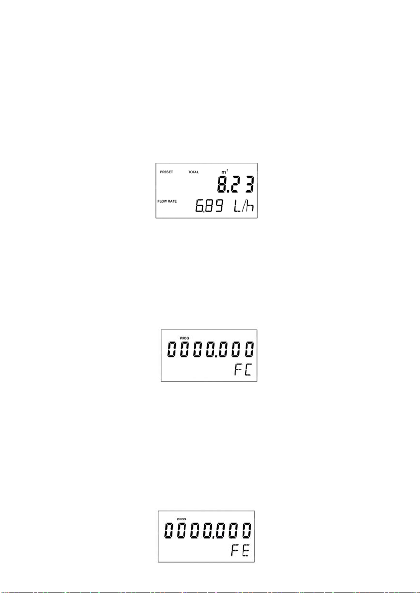
In the case of using a par-pos cable, which has two shielded pairs of cables (one for the
electrodes and one for the coils) there is only one shield for the two electrode cables. In this
case P1, P2 and COM terminals should be connected together and the electrode shield
should be connected to one of these terminals and to the COM terminal.
3 OPERATION
The equipment is normally delivered calibrated and configured with its sensor so that it
indicates the true flow rate and volume. If any configuration parameter is to be changed,
this can be done without having to remove the top cover.
If the instrument has not been previously configured or, due to alteration of data in the
memory the instrument recovers the default configuration, the word “PRESET” appears on
the display. This indication disappears when the sequence of configuration has been
completed.
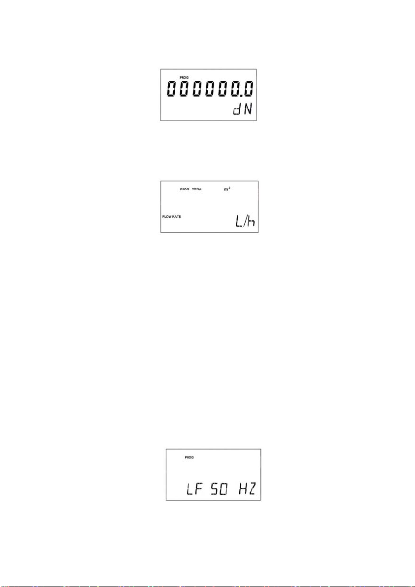
In all the configuration screens the (
making any changes in the configuration data even if digits have been changed.
3.1 Configuration of the flow rate calculation parameters
Touching the two keys (↑) & (←) at the same time the flow rate configuration process is
entered.
3.1.1 Sensor factor
The first screen is to configure the sensor factor (Fc), which is given on the sensor label.
Touching the key (↑) the flashing digit will be increased. When the value of 9 is reached,
on the next increment the digit will go to Zero. With the key (←) we move to the next digit
to the left. If we are on the seventh digit we will go back to the first digit.
When we have the required factor on the screen, touching the two keys (↑) & (←) at the
same time, the data will be stored in memory and the next screen will appear.
If not specified, the keys for the next screens have the same functions as in this first
screen.
3.1.2 Electronics factor
In this screen we must introduce the electronics factor (Fe), which is indicated on the label
on the front cover.
□) key is used to jump to the next screen without
10
Page 11
3.1.3 Nominal diameter
In this screen the nominal diameter (internal diameter) in millimetres of the sensor, or the
pipe size in the case of a Flomat, is entered.
3.1.4 Measuring units
In the next screen the flow rate and volume totalizer units are selected.
To change the flow rate units the key (↑) is used. To change the volume totalizer units the
key (←) is used.
The possible units for the flow rate and the volume totalizer are the following:
Flow Rate:
There are 9 combinations for the 3 units for volume and the 3 units for time.
Volume / time
l (litres) / s (second)
m3 (cubic metres) / m (minute)
ga (US gallons) / h (hour)
Volume totalizer:
There are 3 possible units for volume, l (litres), m3 (cubic metres), ga (US gallons).
Note: 1ga = 3.785 litres.
If the instrument has a mains power supply connection with the selected working units,
touching the two keys (↑) & (←) at the same time, we return to the normal working
screen.
3.1.5 Mains frequency
If the instrument has a DC power supply, user must configure the mains frequency of the
country where the instrument is installed. This is done for filtering out line frequency noise
found in the electrodes signal.
With the (↑) key the local mains frequency is selected (50 Hz or 60 Hz) and touching the
two keys (↑) & (←) at the same time, we return to the normal working screen.
11
Page 12
3.2 Con figuration of the rest of the parameters.
Touching the two keys (↑) & (
display and output parameters is accessed.
3.2.1 Decimals
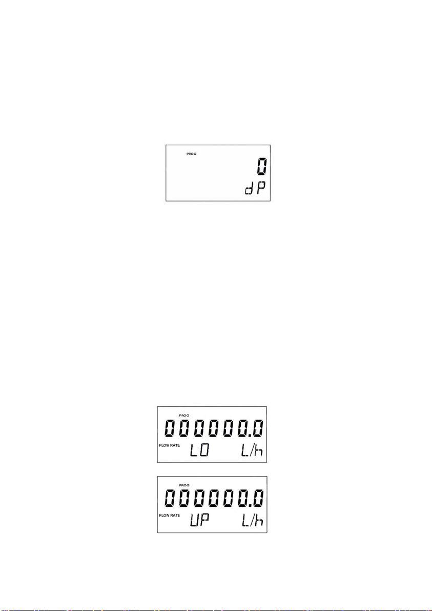
In the first screen the number of decimals for the flow rate indication is configured.
For this, touching the key (↑) the flashing digit will be increased. When the value of 2 is
reached, on the next increment the digit will go to zero. When we have the required factor
on the screen, touching the two keys (↑) & (←) at the same time, the data will be stored in
memory.
To select the number of decimals it must be taken into account that the instrument has 4
digits for flow rate indication. If two decimals have been selected, these will be seen
whilst the flow rate is not greater than 99.99. Above this value the indication will
automatically change to one decimal, and when the flow rate is greater than 999.9 the
indication will be done without decimals.
If one decimal is selected, the flow rate indication will have a maximum of one decimal.
If indication without decimals is selected, the flow rate will always be shown without
decimals.
For the selection of the flow rate units and the number of decimals it must be taken into
account that an indication with an excess of decimals may give the sensation of instability
of the reading. As a general rule it can be considered that the reading should not have
more than a total of 3 digits (integer + decimals).
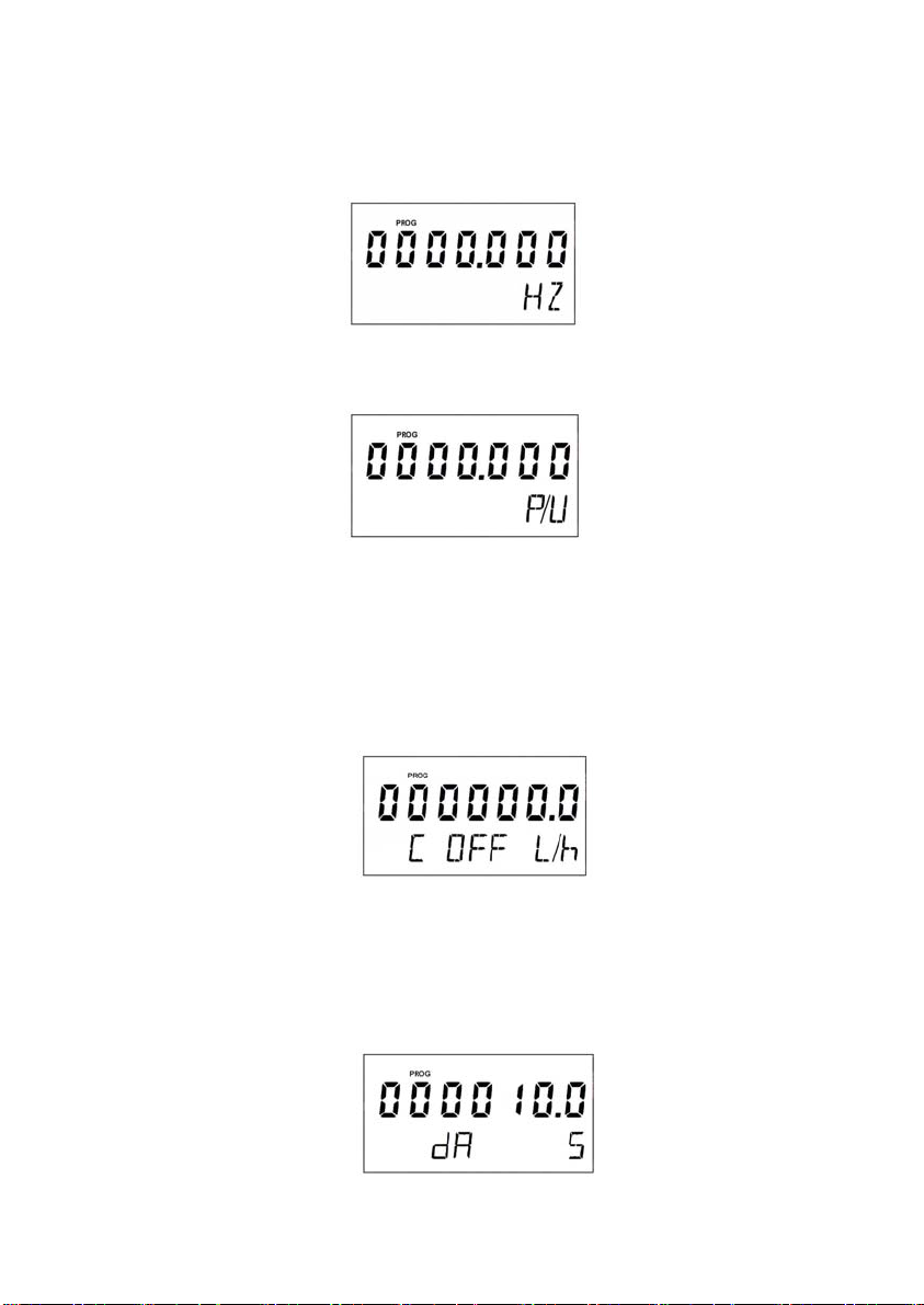
3.2.2 Current output
Next, the screens for programming the current loop appear. The flow rate units will be
those selected previously.
□) at the same time the configuration sequence for the
In the first screen the flow rate for the 4 mA point (lower range) is configured. In the next
screen the flow rate for the 20 mA point (upper range) is configured.
12
Page 13
3.2.3 Pulse output
In this screen, there are two options.
a) Frequency output (Hz). This is meant for transmitting the instantaneous flow rate to a
remote unit. The output pulse frequency for a flow velocity of 5 m/s is programmed
here (see limits in 9.3).
b) Pulse output per unit of volume (P/U). This is meant for remote totalizing. The number
of pulses per unit of volume totalizer are programmed here. The pulse width is 80 ms.
The maximum frequency is 6.25 Hz.
First the pulse output mode (Hz or P/U) is selected using the (↑) key. Once the output
mode is selected, touch the (←) key and then enter the corresponding numerical value for
the frequency at 5 m/s or pulses/unit according to the output mode selected.
3.2.4 Cut off
The sensor Flomid/Flomat with converter XT5, being an electromagnetic flow meter, has
its maximum deviation in the low end of its working range. Due to this, a cut off flow rate
can be configured, that means, the flow rate below which the flow rate indication will be
zero.
3.2.5 Damping
The Flomid/Flomat XT5 flow meter has an adaptive filter (damping) to provide stable flow
rate and analog output readings in the presence of continuous flow rate fluctuations.
The configuration of this filter can be very useful in the cases where the flow rate readings
have some instability (due to air bubbles, solids in suspension, etc…).
13
Page 14
Only the flow rate indication of the display and the analog output are affected by the filter.
The pulse output and the totalizer act according to the instant flow rate. By selecting a
filter with a longer or shorter integration time will provide more or less stable readings and
will also affect the response time to small variations of flow rate.
The integration time is selected in seconds, with a minimum value of 0.1 and a maximum
value of 20.0 seconds. For example, with an integration time of 15 seconds, the display
will indicate the flow rate reading of the average flow rate over the last 15 seconds from the
last update of the display. This does not mean that the display is refreshing its data every
15 seconds. The display shows a new value several times per second, indicating an
average of the flow rate values of the last 15 seconds.
When there is a sudden variation of the flow rate then the filter should react as fast as
possible to give a correct reading of the new value. For this, the filter controls for each
reading the deviation of the instant flow rate with respect to a reference. If this deviation
exceeds the established limits, the filter will stop acting, indicating the instant value, and
will start again the filtering process.
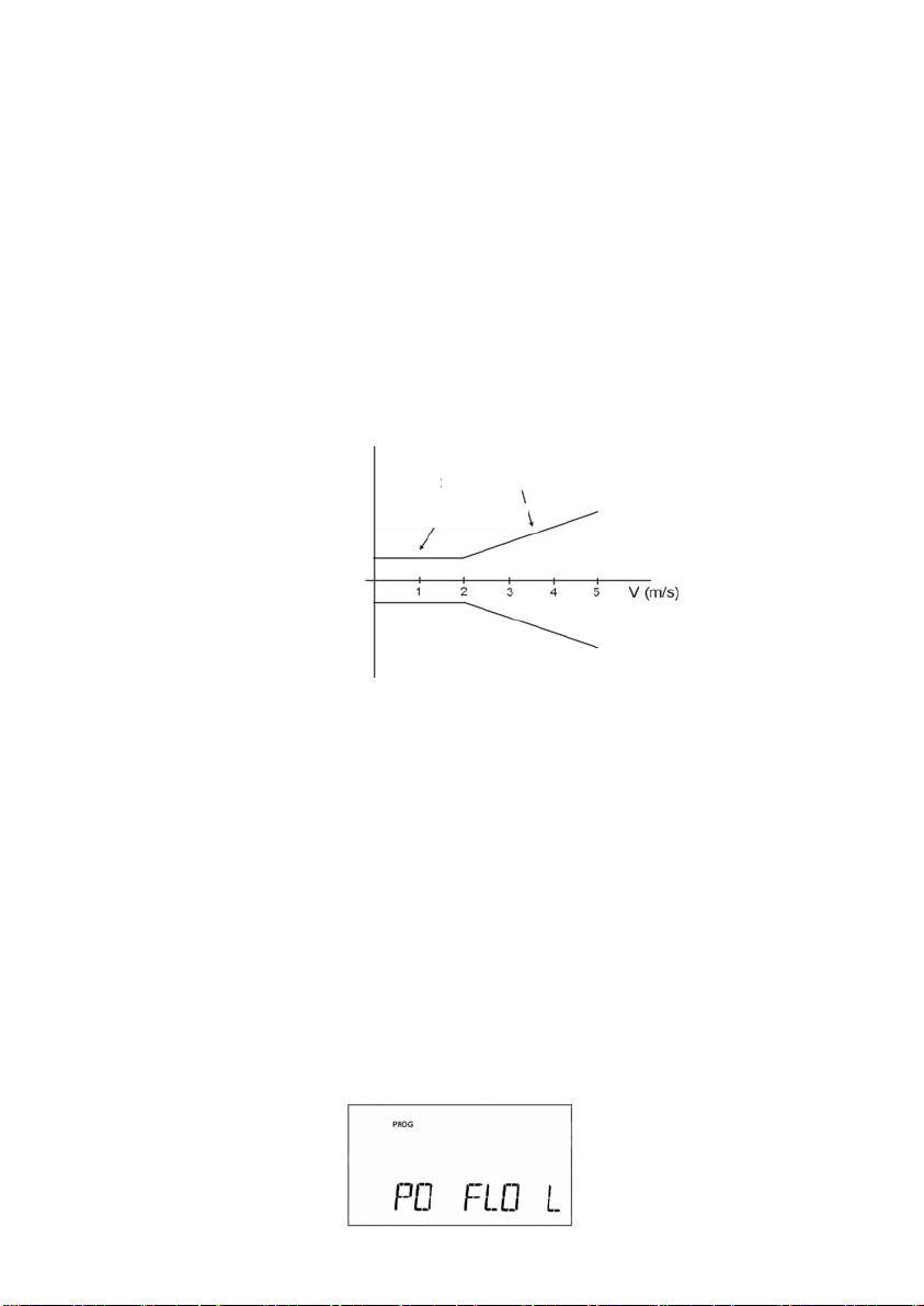
In the following figure we can see the allowed deviation for the filter to continue giving
average values.
25% of instant flow rate
10% of nominal flow rate
Average flow rate
For example, consider a DN25 flow meter whose average flow rate is 4000 l/h.
4000 l/h corresponds to a liquid velocity of 2,27 m/s, situated in the second zone of the
graphic. This means that the filter will continue giving average readings whilst the instant
flow rate does not deviate more that 25% (1000l/h) from the average flow rate.
Since the average flow rate is 4000 l/h, the filter acts whilst the instant flow rate is within
3000 l/h and 5000 l/h.
If the average flow rate is for example 2000 l/h, it corresponds to a liquid velocity of 1,14
m/s, in this case we are in the first zone of the figure. This means that the filter will
continue acting whilst the instant flow rate does not deviate from the average flow rate
more that 10% from the nominal flow rate, that is 880 l/h (flow rate at 0,5 m/s in a DN25 =
880 l/h).
Since the average flow rate is 2000 l/h, the filter continues to act whilst the instant flow
rate is within 1120 l/h and 2880 l/h.
3.2.6 Flow rate direction
In this screen the flow direction for which the flow rate indication will show a positive value
can be programmed.
14
Page 15
Using the (↑) key we change the positive flow direction from left to right (R) to right to left
(L).
Note: In a Flomid sensor the left and right of the sensor are when looking at the sensor in
a horizontal pipe and with the earth connection stud at the back. In a Flomat sensor left
to right flow is indicated by the arrow on the sensor.
When the flow rate is negative the volume totalizer will not count.
3.2.7 Empty pipe detection
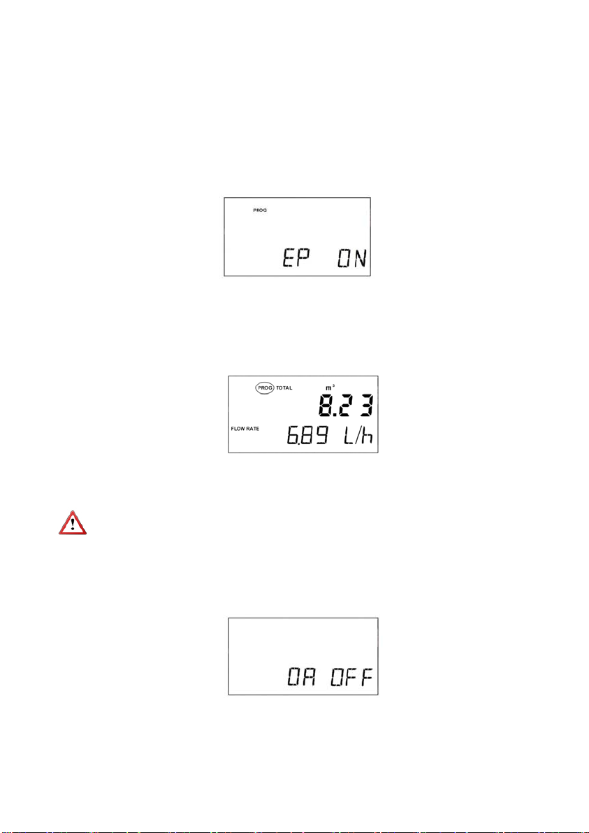
In the last screen the empty pipe detection (EP) can be enabled or disabled, using the (↑)
key to change from ON (enabled) to OFF (disabled)
In an XT5H converter, if during a configuration sequence a HARTTM command, which
should be attended, is received, the local configuration sequence will not be valid and all
the data of that configuration sequence will be lost. The screen will return to the normal
working screen and the word “PROG” will be displayed to show that this event has
occurred. The word “PROG” will be turned off when touching either of the two keys (↑) or
(←).
3.3 Zero o ffset adjustment
In order to obtain a perfect linearization of the instrument, it is recommended to make an
adjustment of the zero offset.
IMPORTANT: The flow meter is delivered with the zero offset adjusted. Do not make a
new adjustment if not necessary. An adjustment not done properly can become in
incorrect flow rate values.
In order to make the adjustment, it is necessary that the flow rate through the instrument
is zero.
The first step is to deactivate the adjustment. To do this, press the key (←) and the
following screen is displayed.
Press the key (↑) until the word OFF appears. Press then the keys (←) & (↑). With this,
the adjustment is deactivate.
Before doing the next step, be sure that the pipe is full and that there is not flow rate
through the instrument.
Press the key (↑) again and change until the word ON appear. Press the keys (←) & (↑)
and the zero offset adjustment is completed.
15
Page 16
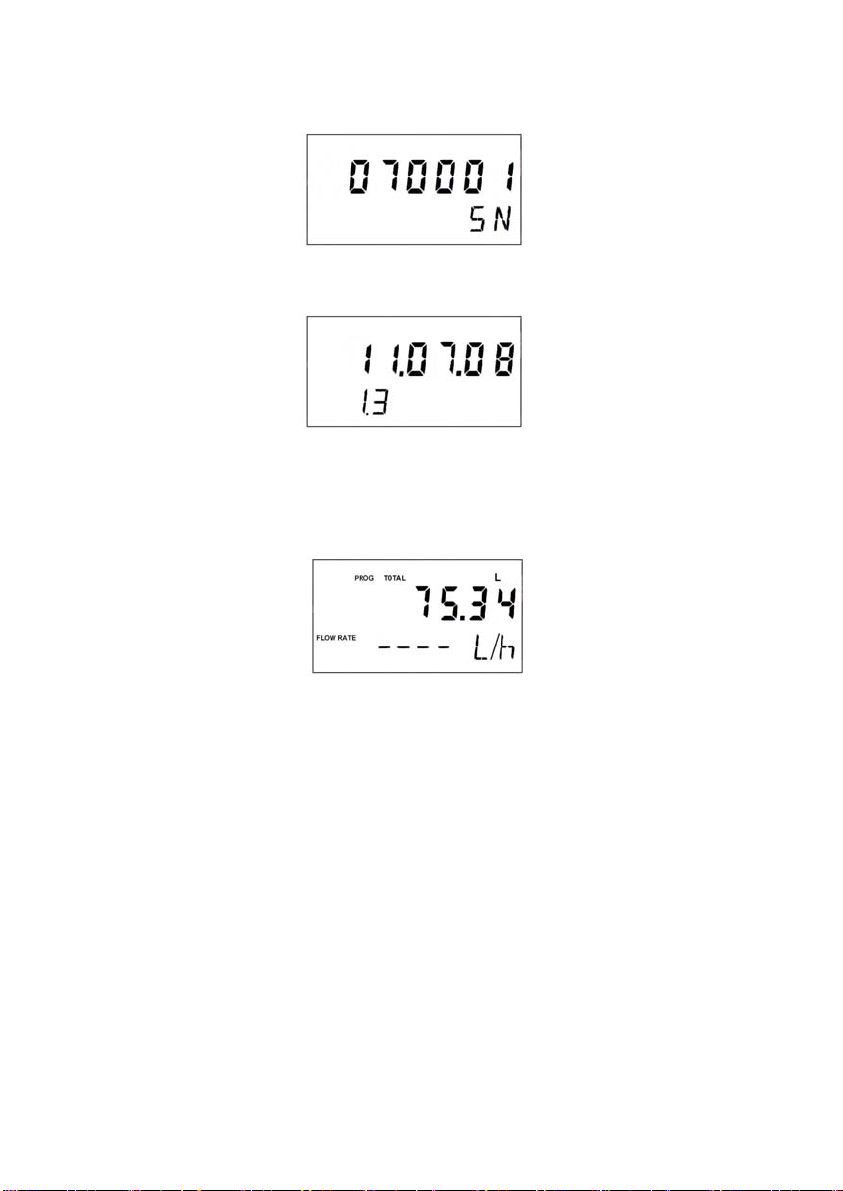
3.4 Visualization of the serial number and software version
Touching the three keys at the same time we access a screen where the serial number of
the converter is shown.
In order to see the software version and return to the normal working screen, touch any
key.
3.5 Empty pipe indication
When the XT5 detects that the pipe is empty the flow rate indication will disappear and in
its place 4 dashes will be shown.
NOTE: When the XT5 is connected to the power supply the screen shows Empty Pipe
until this state has been checked.
3.6 Reset
Touching the (←) and (
□) keys at the same time the volume totalizer counter will be reset
to zero and it will continue counting.
4 KEYBOARD DISABLE AND “WRITE PROTECT”
The instrument has a jumper, placed behind the display on the left side, which can be
used to avoid changes in the configuration. When the jumper is connected the instrument
can be configured by means of the keyboard and via HART
removed, the keyboard is disabled and “Write Protect” is activated for HART
avoiding any changes in the configuration.
5 CHANGING THE POSITION OF THE DISPLAY
To change the orientation of the display in order to adapt it to the instrument mounting
position, first disconnect the equipment from the power supply and remove the front
cover. Remove the three screws that hold the display PCB to the base PCB (two screws
in the corners opposite to the terminal strip and one central screw next to the terminal
strip). Holding the PCB, pull on it to disconnect it. Rotate the display PCB 180º and
reconnect it to its connector avoiding the pins to be bent. Reassemble the three screws
that hold the display PCB and reassemble the front cover. Reconnect the instrument to its
power supply
TM
6 HART
COMMUNICATION
The XT5H converter has a MODEM for HART
TM
16
communication.
TM
. When the jumper is
TM
, thus
Page 17
The detail of the characteristics with respect to the HARTTM communication are available
in the corresponding “Field Device Specification” document.
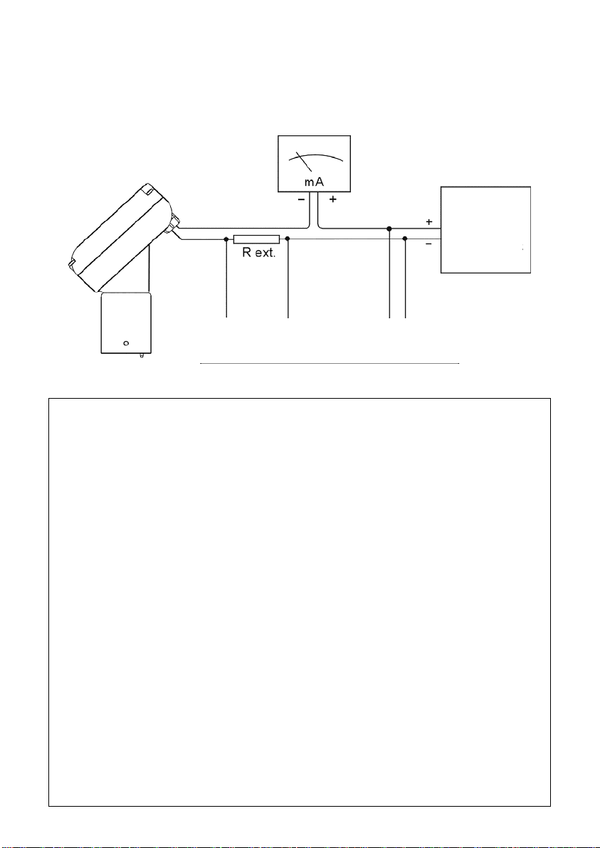
To be able to use HART
be lower than 200 Ohms, should be added to the current loop. The points at which a
terminal or a PC with a HART
figure.
TM
communication, a resistance (R ext.), whose value must not
TM
modem can be connected are shown in the following
Power
Supply
18 to 36 V
Connection points for a HARTTM terminal
or a PC with HART
Summary of the principal communication characteristics:
Manufacturer, Model and Revision Tecfluid S.A., XT5 converter, Rev. 1
Device type Transmitter
Hart Revision 6.0
Device Description available No
Number and type of sensors 1, exterior
Number and type of actuators 0
Number and type of host side signals 1, 4 – 20 mA Analog
Number of Device Variables 2
Number of Dynamic Variables 1
Mappable Dynamic Variables No
Number of Common Practice Commands 14
Number of Device Specific Commands 8
Bits of Additional Device Status 17
TM
modem
Burst mode? No
Write Protection? Yes
17
Page 18

7 MAINTENANCE
No special maintenance is required .
For cleaning, a humid cloth can be used, and if necessary with a little soap. Solvents or
other aggressive liquids which could damage the housing (polycarbonate) should not be
used.
7.1 Fuse
In the event that the fuse blows, this should be replaced with a slow blow “T” fuse, size
Ø5 x 20 mm and of the same rating as indicated on the label inside the equipment.
8 EXAMPLES OF USEFUL CALCULATIONS
8.1 Measurement error correction
The calibration of flow meters is made with water at 20
liquid density of 1 kg/l and viscosity of 1 mPa·s. If the flow meter is used with a liquid of
other characteristics from the above specified or for reasons of turbulences in the flow,
measurement errors can be induced.
To correct these types of errors we can modify the value of the Fc factor programmed in
the instrument.
Example - Shortage of volume
If we have a flow meter body which specifies Fc = 0.985, and when we check the volume
of a batch, we find that instead of having 100 litres as programmed, we only have 95 litres
(5% less), then the following correction must applied:
o
C, obtaining a calibration for a
Fc = Original sensor factor = 0.985
V = Expected Volume = 100
Vr = Real Volume = 95
Fcn = New sensor factor = ? (1.037)
8.2 Con figuration of pulses / unit of volume
As indicated in the point 3.2.3, the maximum frequency of the pulse output in mode
pulses / unit is 6,25 Hz. In order to know if the desired number of pulses per unit of
volume can reach this frequency, the following formula can be applied:
F
cn
F
=
V
c
V
r
Where
fmax = Maximum frequency at the output
Flow rate
F
p/u
Example - Sensor DN 25 and programmed Factor = 100 pulses / litre
Firstly, we need to know what is the maximum flow rate that could pass through the flow
meter. For example 9500 litres / hour.
Changing the flow rate to units of volume per second we obtain:
Note that the units of volume are litres because in this example the programmed factor is
100 pulses / litre.
18
(u/s) = Maximum flow rate in units of volume per second
max
= Factor of pulses per unit of volume programmed in the converter
F(u/s)rateFlow f
p/umaxmax
second / litres 2.639 3600 / 9500
Page 19

In this case, applying the formula, the maximum frequency at the output is:
As the value exceeds 6.25 Hz, this factor can not be applied.
In this case there would be 2 solutions:
1. To change the factor to 1 pulse per litre, becoming the maximum frequency 100 times
smaller, fmax = 2.639 Hz.
2. To change the units of volume to m3. With this, the maximum flow rate is divided by
1000 and therefore the maximum frequency becomes fmax = 0.2639 Hz.
9 TECHNICAL CHARACTERISTICS
9.1 Power supply
230, 240, 115, 24 VAC 50, 60 Hz . 24 VDC.
Power consumption: ≤ 5 VA
9.2 Analog output
4-20 mA. Active or passive. Galvanically isolated from the power supply.
9.3 Pulse output
Opto-isolated. Vmax: 30 VDC. Imax: 30 mA.
Maximum frequency in mode “P/U” : 6.25 Hz
Maximum frequency in mode “Hz” : 10 000 Hz
Minimum frequency in mode “Hz” : 0.04 Hz
Optional: Vmax: 240VAC / 350 VDC. Imax: 100 mA
Maximum frequency in mode “P/U” : 6.25 Hz
Maximum frequency in mode “Hz” : 75 Hz
9.4 Totalizer
Nº of digits: 7 (2 decimals)**
Digit size: 8 mm
Reset: By means of key
9.5 Flow rate indication
Nº of digits: 4 (up to 2 decimals configurable)**
Digit size: 5 mm
** When the available digits are full and the integers overflow a decimal is automatically
lost.
9.6 General characteristics
Protection rating: IP67
Ambient temperature range: 0 ... +60 ºC
9.7 Electrical characteristics referred to the analog loop and communications
Reception impedance:
Rx > 8,5 MΩ
Cx < 200 pF
max
Hz 263.91002.639f
This equipment complies with the following EEC directives:
Low voltage (73/23/CEE)
Electromagnetic compatibility (89/336/CEE)
19
Page 20
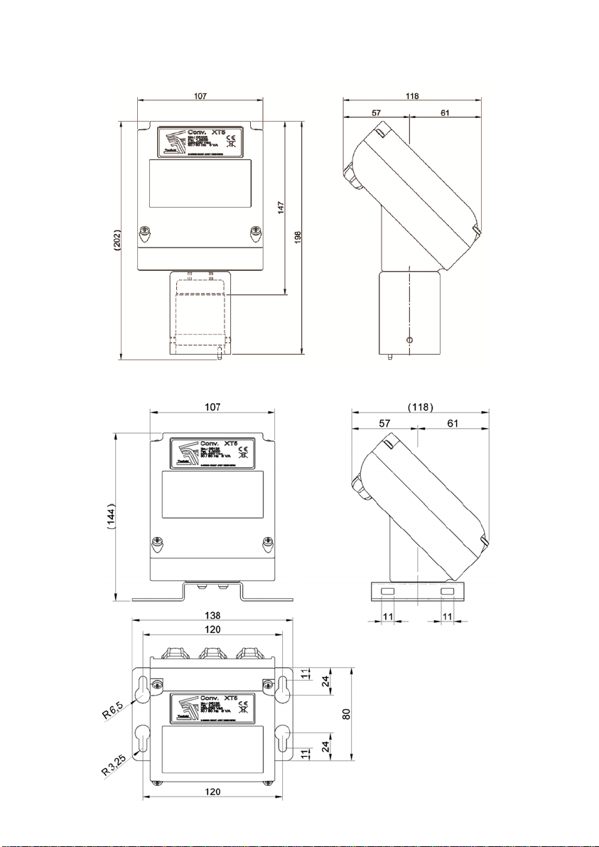
10 DIMENSIONS
COMPACT MODEL
WALL MOUNTING MODEL
20
Page 21

11 TROUBLESHOOTING
Problem Probable cause Remedy
Make sure that the pipe is
completely full, installing the flow
meter in a section upstream of the
pipe.
Connect the functional ground of
the flow meter to a metallic point
of the installation in contact with
the liquid.
The flow rate is not
displayed. In its place
there are dashes
The pipe is empty.
The functional earth is not
connected.
Isolation of the electrodes. Clean the sensor electrodes.
The flow rate is
unstable
The flow rate displayed
is 0
The instrument displays
a value when there is
not flow
The flow rate displayed
is higher than expected
Electrode cable disconnected
Liquid with very low conductivity
Dirt on the electrodes. Clean the sensor electrodes.
The product contains air or nonconductive particles in suspension.
Alignment of the sensor (Flomat)
Coil cable disconnected
The flow rate is smaller than
programmed as CUT OFF.
The sensor is damaged due to
electrodes corrosion.
The functional earth is not
connected and the empty pipe
option is OFF.
The electrodes are immersed but
the pipe is not completely full.
Connect the cable between the
sensor and the electronic
converter.
The flow meter is not adequate for
the application.
Verify that the flow meter is
adequate for this application.
Verify that the orientation of the
sensor is such that the arrow is
orientated along the direction of
the fluid.
Connect the cable between the
sensor and the electronic
converter.
Decrease the value of the cut off
(see page 9).
Electrode material not adequate
for the liquid.
Connect the functional ground of
the flow meter to a metallic point
of the installation in contact with
the liquid.
Make sure that the pipe is
completely full, installing the flow
meter in a section upstream of the
pipe.
21
Page 22
Problem Probable cause Remedy
The display is blank Fused fuse. Change the fuse.
The analog output gives
always 4 mA or 20 mA
The analog output gives
0 mA
The pulse output does
not work well
The totalizer does not
change its value
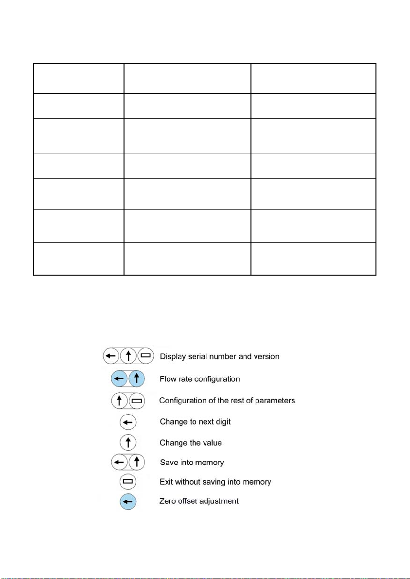
The keys do not act The keys are locked “write protect”
12 PROGRAMMING DIAGRAM
Current output range not properly
programmed.
Cable disconnected Check the cable connection
In pulse / unit of volume mode, the
frequency is higher than 6,25 Hz
The flow rate is negative (with
respect to the fluid direction)
Program the range properly (see
page 9).
Decrease the pulses / unit of
volume or change to frequency
output mode (see page 9).
Program the positive flow rate
direction according to the fluid
direction (see page 11).
Unlock the keys by placing the
jumper (see page 13).
22
Page 23
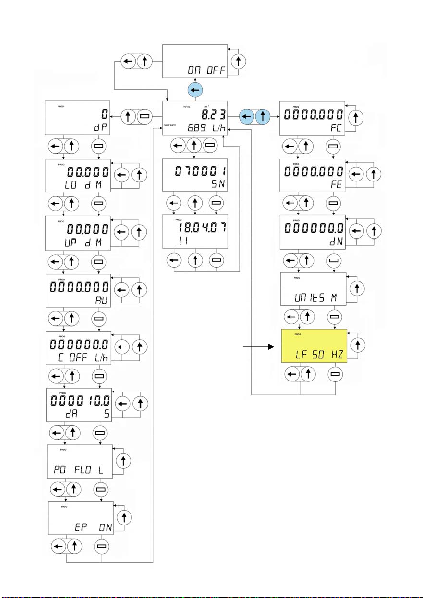
Only in equipment
supplied by direct
current (DC)
dP: Number of decimal digits
LO: Equivalent flow rate to 4 mA in the current loop
UP: Equivalent flow rate to 20 mA in the current loop
P/U: Pulses / unit of volume or frequency at 5 m/s
C OFF: Value below which the flow rate is considered zero
dA: Damping. Filter value to damp the measurement
PO FLO: Direction for a positive flow rate
EP: Empty pipe activation
OA: Zero offset adjustment
SN: Serial number
FC: Sensor factor
FE: Electronics factor
DN: Nominal diameter
Units: Measuring units
LF: Mains frequency
23
Page 24

WARRANTY
Tecfluid S.A. GUARANTEES ALL ITS PRODUCTS FOR A PERIOD OF 24 MONTHS, after
consignment, against all defects in materials and workmanship.
This warranty does not cover failures which can be imputed to misuse, use in an application different
to that specified in the order, the result of service or modification by un-authorized persons, bad
handling or accident.
This warranty is limited to cover the repair or replacement defective parts which have not been
damaged by misuse.
This warranty is limited to the repair of the equipment and all further and eventually following
damages are not covered by this warranty.
Any consignment of equipment to our factory or distributor must be previously authorised. The
consignment should be done with the equipment well packed, clean of any liquids, grease or
hazardous materials.
Together with the equipment, a note should be enclosed indicating the failure observed, the name,
address and telephone number of the sender.
SHIPPING
In the event of damages during shipping, claim directly to the carrier over a period of less than 24
hours. Tecfluid is not responsible for any damage caused during the shipment of material.
TECFLUID, S.A.
Narcís Monturiol, 33
E-08960 Sant Just Desvern
Tel. + 34 93 3724511 - Fax + 34 93 4734449
E-mail: [email protected]
Internet: www.tecfluid.com
The technical data in this document is subject to modification without notification, if the technical innovations in the product or
manufacturing processes so require.
 Loading...