

Page 1

INSTRUCTION MANUAL FOR THE MC-01 CONTROL UNIT
TABLE OF CONTENTS
1 INSTALLATION
1.1 Mounting
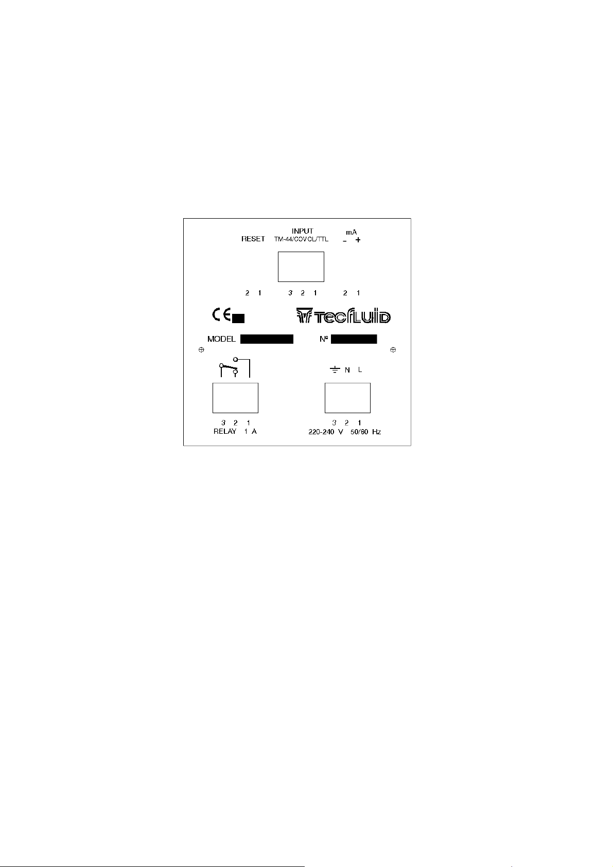
1.2 Mains Connection
1.3 Relay Connection
1.4 Pulse Input Connection
................................................................................................................ 2
............................................................................................................. 2
............................................................................................ 2
.............................................................................................. 3
.................................................................................... 3
1.5 4 - 20 mA Output Connection (optional
1.6 Remote Reset Connection (optional)
............................................................. 3
2 SETTING UP AND PROGRAMMING
2.1 Description of the front panel
2.2 Starting up
.......................................................................................................... 5
............................................................................. 4
.......................................................................... 4
2.3 Basic Configuration of the equipment
2.4 Programming the 4 - 20 mA Output
2.5 Selection of the analog output range
................................................................ 6
............................................................. 6
2.6 Selection of the normal working screen
3 BATCHING
3.1 Entering the preset value
3.2 Batching
....................................................................................................................... 7
................................................................................. 7
.............................................................................................................. 8
4 TOTALIZING COUNTER
................................................................................................. 8
5 ERROR MESSAGES
....................................................................................................... 8
6 USEFUL EXAMPLES OF CALCULATIONS
.................................................................. 9
7 TECHNICAL CHARACTERISTICS
7.1 Power supply
7.2 Signal Inputs
7.3 Auxiliary Inputs
7.4 Relay Outputs
................................................................................................... 10
.................................................................................................... 10
................................................................................................ 11
................................................................................................. 11
7.5 4 - 20 mA Output (Optional)
7.6 Working Conditions
7.7 Dimensions
.................................................................................................... 12
............................................................................... 10
........................................................................ 11
........................................................................................ 11
1
)........................................................ 3
.......................................................... 5
........................................................ 7
Cod:E-MI-2151061 I Rev:1
Page 2
2
1 INSTALLATION
1.1 Mounting
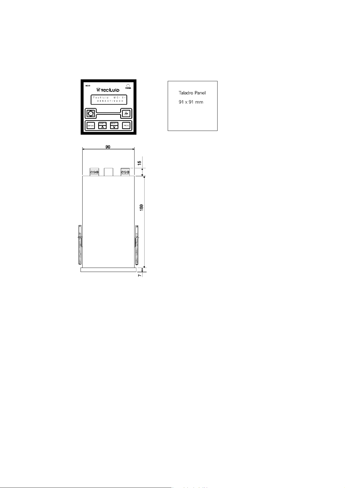
The MC-01 control instrument is housed in a DIN 96 x 96 type plastic case intended to be mounted in a
front panel of an electrical control panel via a 90 x 90 mm +0.5mm/-0mm square hole. The electrical control
panel should have a minimum depth of 190 mm behind the front panel to take the MC-01.
IMPORTANT : In order to comply with the electrical safety requirements as per IEC 1010-1, the installation
of the equipment must take into account the following:
- The equipment must be installed in the front panel of an electrical mounting cabinet, leaving
only the front of the equipment accessible to the operator.
- A mains switch must be provided to disconnect the equipment. This switch must be marked
as the disconnecting device for the equipment and be within easy reach of the operator.
- The mains supply must have an earth line.
1.2 Mains Connection
The connection of the equipment is via plug-in connectors, polarized to avoid mistakes when plugged
in. The connectors have screw terminals, as per VDE norms, to accept 1,5 mm
2
cable.
When we refer to the positions of the connectors, it is looking at the back of the MC-01.
The connector for the mains power supply is situated on the bottom right-hand side, in which the
power supply (voltage indicated below the connector) must be connected to terminals Nº1 and Nº2.
Terminal Nº3 should be connected to a good earth. The MC-01 has a Φ 5 x 20 mm mains fuse inside. The
nominal rating of this fuse depends on the mains voltage.
Cod:E-MI-2151061 I Rev:1
Page 3

3
1.3 Relay Connection
The connector for the Relay is marked "
RELAY 1A
" (situated on the bottom left-hand side). The
common contact of the relay is terminal Nº3. The normally open contact (with the relay disactivated) is
terminal Nº1 and the normally closed contact is terminal Nº2. There are no provisions for protection of the
relay contacts inside the MC-01, neither fuse nor over-voltage protection (such as may be needed with
inductive loads), and these must be provided externally as required.
1.4 Pulse Input Connection
The connection to the input from the pulse generator (flowmeter or volumetric counter) must be
made using shielded cable with two live wires and the external shield. The external shield must be
connected to the chassis of the pulse generator and to terminal Nº1 on the input connector of the MC-01
which is marked "
INPUT" "TM44", "COVOL" or "TTL"
depending on the type of input pulse.
The input cables must not be installed close to power lines as these will induce interferences in the
input lines causing errors in the readings.
A. COVOL
MC-01 Terminal Nº to COVOL connector terminal Nº
1 Shield 1 Shield
2 Live 2 Live
3 No connection
B. TM-44
MC-01 Terminal Nº to TM44 connector terminal Nº
1 Shield 1 Shield
2 Live 2 Live
3 Live 3 Live
C. TTL
MC-01 Terminal Nº
1 Common
2 Live
3 No connection
1.5 4 - 20 mA Output Connection (optional)
The connections to the 4-20 mA output are made to the connector marked "
" (situated on the
mA
top right-hand side). Terminal Nº1 is the positive of the output and terminal Nº2 is the negative.
The maximum passive load that can be applied to this output is 350 ohms. The use of higher
resistive loads can cause saturation of the output and then you will not get the full 20 mA output.
1.6 Remote Reset Connection (optional)
The input for the remote Reset is intended for a normally open electrical contact connected between
terminals Nº1 and Nº2 of the connector situated at the left of the connector marked "
INPUT"
.
The connection to the input from the remote Reset must be made using shielded cable with two live
wires and the external shield. The external shield must be connected to the chassis of the remote Reset and
to terminal Nº1 on the input connector of the MC-01 which is marked "
INPUT"
. The two live wires are
connected to the terminals of the remote Reset connector.
The input cables must not be installed close to power lines as these will induce interferences in the
input lines causing errors in the equipment.
Cod:E-MI-2151061 I Rev:1
Page 4
4
2 SETTING UP AND PROGRAMMING
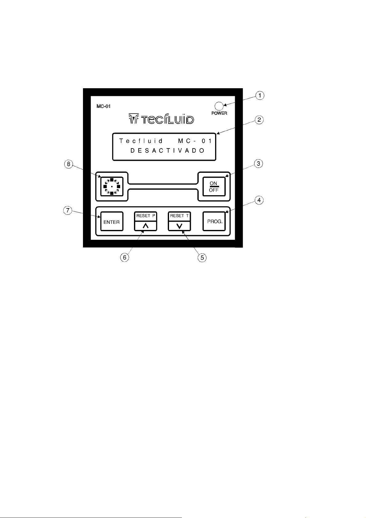
2.1 Description of the front panel
1. Red LED power supply pilot light .
2. LCD Display (2 lines with 16 characters per line )
3. "ON/OFF" Push-button
4. "PROG." Push-button
5. "RESET T" or "Decrement Data" Push-button
6. "RESET P" or "Increment Data" Push-button
7. "ENTER" Push-button
8. "Rotation" Push-button
The MC-01 has six Push-buttons to control the different working modes as explained in these
instructions. The Liquid Crystal Display (LCD) is used to visualize the working data and messages of the
equipment. The LED pilot light is only for indicating the presence of mains supply voltage; in the event that
the mains fuse blows, the pilot light will be off.
Cod:E-MI-2151061 I Rev:1
Page 5

2.2 Starting up
When the mains supply is connected and the MC-01 has been previously programmed the selected
normal working screen will automatically appear. To program the MC-01 we must start from the "Standby"
screen. If the normal working screen is displayed, by pressing the
back to the "Standby" screen for programming.
2.3 Basic Configuration of the equipment
The "Standby" screen must be displayed in order to be able to enter in the programming screens.
"ON/OFF" [3]
push-button we will go
5
Tecfluid MC-01
Standby
From this screen we can enter the basic configuration sequence by pressing the
button. Pressing this push-button, the first screen for programming the pulses per litre (Factor I/L) appears.
"PROG." [4]
push-
Enter Factor I/L
>000,000
When the programming screen appears the cursor is below the first digit to modify. The "
"∧"
push-button is used to increase the value of the number and the "
[6]
its value. Once the desired value of the digit in question is achieved using the previously mentioned pushbuttons, by pressing the "
value of less than 1 is introduced, the flow-rate will be displayed in cubic meters per hour instead of litres per
hour. The preset value will always be in litres (see part 3.1). When the
the value displayed on the screen will automatically be saved in memory and the next programming screen
will appear.
ENTER" [7]
push-button the cursor will pass to the next digit to be modified. If a
RESET P
RESET T" "∨" [5]
"PROG." [4]
is used to reduce
push-button is pressed
Enter Factor I/L
>788,500
"
Cod:E-MI-2151061 I Rev:1
Page 6

6
2.4 Programming the 4 - 20 mA Output
In the event that the MC-01 has a 4-20 mA output the following screens will appear to program the
beginning and end of the analog output scale. First will appear the screen to program the beginning of the
analog scale (flow-rate for 4 mA).
B. Scale Litres
>000100
B. Scale m3
>000100
The value of the flow-rate must be entered in litres per hour or in cubic meters per hour depending
on the indication of the screen. Once this data has been entered, using the push-buttons in the same way as
previously described for entering the I/L Factor, the next screen will appear to enter the flow-rate for the end
of the scale for 20 mA output.
E. Scale Litres
>001000
E. Scale m3
>001000
In this screen we must enter the flow-rate for a 20 mA output. Once this data has been entered,
using the push-buttons in the same way as previously described for entering the I/L Factor, the next screen
will appear to select the normal working screen.
2.5 Selection of the analog output range
The analog output range is selected using the
options and the
"PROG." [4]
Analog Output
push-button to validate the option selected.
Analog Output
4-20 mA
"ENTER" [7]
push-button to select one or other
0-20 mA
Cod:E-MI-2151061 I Rev:1
Page 7

2.6 Selection of the normal working screen
In this part of the programming sequence we select the screen that will appear when the equipment
is turned on. There are six possible screens of which we must select one.
7
Partial Total
Q m3/h Partial
Q m3/h Total
Using the
appears. By pressing the
working screen,the programming sequence will finish and the "Standby" screen will appear.
It can be seen that there are options to select the flow-rate (Q) to be given in litres per hour (l/h) or in
cubic meters per hour (m3/h). If the l/h option is selected, the flow-rate will be given in litres per hour unless
the flow-rate reaches 20,000 l/h and above which it will be displayed in cubic meters per hour. If the m3/h
option is selected, the flow-rate will be given in cubic meters per hour unless the flow-rate drops to 5 m3/h
and below which it will be displayed in litres per hour.
In the event that the "Factor I/L" is less than one, there will be only four options to select the normal
working screen; given that the flow-rate will always be in m3/h.
This selection of the normal working screen is only to select the screen that will appear when the
power is switched on, or when one changes from the "Standby" screen to the working screen. When in a
working screen, it can be changed for another by using the
enter the programming sequence.
"Rotation" [8]
push-button we can rotate between the six options until the desired screen
"ENTER" [7]
push-button the displayed screen will be selected as the normal
Q l/h Partial
Q l/h Total
Preset Partial
"Rotation" [8]
push-button, without having to
3 BATCHING
3.1 Entering the preset value
Starting from the "Standby" screen, by pressing the
screen to program the preset value in litres for batching.
"Rotation" [8]
Preset.(litres):
>000000
The use of the push-buttons is as explained in part 2.3
push-button we can enter in the
Cod:E-MI-2151061 I Rev:1
Page 8

8
3.2 Batching
From the "standby" screen, we press the "
screen. The normal working screen will appear, selected as per instructions
ON/OFF" [3]
push-button to enter the normal working
, for example:-
2.4
PRESET. PARTIAL
000000 000000
To start the batching process, first we press the "
counter, and the following screen will appear, but the relay will not yet be activated:
RESET P" [6]
push-button to clear the partial
PRESS ENTER
In the instant that the "
process begins, counting the volume passing through the flowmeter and adding it to the partial and total
counters. When the partial counter reaches the preset value the relay is disactivated and the batching
process finishes.
If the "
and the process is aborted. In this case, instead of showing the normal working screen, the "Standby"
screen appears. By pressing the
screen always shows the state at which the batching was finished. In the event that one needs to finish a
batch which was stopped, by pressing the
preset value equal to the difference between the original preset value and the value of the partial counter
when the process was stopped.
4 TOTALIZING COUNTER
The total counter shows the total volume that has passed through the flowmeter, independently of
the use or not of the batching option.
To clear the totalizing counter, we must go to the "Standby" screen and press the
and
"ENTER" [7]
If the totalizing counter has overflown indicating in litres it will automatically start to indicate in cubic
meters without loosing the data, and in this case the letter "m" will be seen after the number. In this case it is
advisable to put the counter to zero in order not to loose precision in the reading.
ON/OFF" [7]
push-buttons at the same time.
ENTER" [7]
push-button is pressed during the batching process, the relay is disactivated
ON/OFF" [7]
push-button is pressed the relay is activated and the batching
push-button we get back to the normal working screen. This
ON/OFF" [7]
push-button or by a power failure, one must enter a
"RESET T"[5]
5 ERROR MESSAGES
If at some time the input pulses have gone above the maximum input frequency (1900 Hz) an
asterisk will appear between the two blocks of numbers on the bottom half of the screen. In the event that
the input frequency supersedes the maximum input frequency, it can introduce errors in the results of the
calculations of volume.
To clear this error indicator one must press the
"Standby" screen, and then again back to the normal working screen.
"ON/OFF" [3]
push-button twice to pass to the
Cod:E-MI-2151061 I Rev:1
Page 9

6 USEFUL EXAMPLES OF CALCULATIONS
6.1 Measurement error corrections
The calibration of the mechanical flowmeters is accomplished using, for the liquid, water at 20
thus obtaining a calibration for a liquid of density 1 kg/l and viscosity of 1 mPas. If the flowmeter is used with
a liquid of other characteristics from the above specified o for reasons of turbulences in the flow,
measurement errors can be induced.
To correct these types of errors we can modify the pulses per litre ( Factor I/L) programmed in the
MC-01.
Example 1 - Shortage of volume
If we have a flowmeter which specifies 200 pulses per litre, and when we check the volume of a
batch, we find that instead of having 100 litres as programmed, we only have 95 litres (5% less) and we
must apply the following correction:
Fn = Factor Pulses per litre ( new ) = ? (210,526)
F = Factor pulses per litre ( original ) = 200
V = Expected Volume = 100
Vr = Real Volume = 95
9
o
C
F
=
n
In this case counting 200 pulses per litre for 100 litres (total of 20.000 pulses) we have been given in
fact 95 litres, thus we must increase the value of pulses per litre to 210,526.
Example 2 - Excess of volume
If we have a flowmeter which specifies 200 pulses per litre, and when we check the volume of a
batch, we find that instead of having 100 litres as programmed, we only have 105 litres (5% more) and we
must apply the following correction:
Fn = Factor Pulses per litre ( new ) = ? (190,476)
F = Factor pulses per litre ( original ) = 200
V = Expected Volume = 100
Vr = Real Volume = 105
F
=
n
V x F
V
r
V x F
V
r
In this case counting 200 pulses per litre for 100 litres (total of 20.000 pulses) we have been given in
fact 105 litres, thus we must decrease the value of pulses per litre to 190,476.
Cod:E-MI-2151061 I Rev:1
Page 10

10
6.2 Change of units of measurement
In some cases we need to change the measurement units for batching, for example, instead of
working in litres we need to work in kilograms. In this case we will need to know the density of the liquid (ρ).
To change from litres to kg we must divide the pulse per litre factor by the density of the liquid to
obtain the new factor for programming the MC-01. For example, if the liquid has a density of 0.9 and the
flowmeter gives us 200 pulses per litre and we must batch in kg; we will program the MC-01 using 222.222
as the new "Factor I/L" to be able to preset directly in kg.
Fnd = Factor pulses per litre for the new density
F = Original factor for pulses per litre
ρ
= Density of the liquid in kg/litre
F
nd
=
7 TECHNICAL CHARACTERISTICS
7.1 Power supply
The standard mains voltages for the MC-01 are 240 V, 220 V, 110 V, 24 V AC - 50/60 Hz. The
mains voltage must be specified on ordering.
On special order supply voltages of 12 or 24 V DC can be supplied.
The MC-01 consumes less than 3 VA with AC mains supply.
Fuse : 250 mA slow (T)
7.2 Signal Inputs
The MC-01 is designed to accept two types of inputs; on ordering the type must be specified given
that there are differences between the two types.
1. The type of input called "COVOL" is designed to work with an electrical contact which
closes its circuit between the terminals Nº1 and Nº2 of the input connector. Given that this type of
input tends to be very slow, and in order to avoid bounce effects of the contacts, the input frequency
is limited to about 200 pulses per second.
2. The type of input called "TM-44" is designed to work with an inductive pick-up with a coil,
connected to terminals Nº2 and Nº3 of the input connector. The input frequency is limited to about
1900 pulses per second.
F
ρ
Cod:E-MI-2151061 I Rev:1
Page 11

11
7.3 Auxiliary Inputs
An optional input exists for a remote "
RESET P
" to start batching processes. This input is designed
to take a normally open electrical contact between terminals Nº1 and Nº2 of the connector. For this input to
be effective it must be closed during about 200 milliseconds in order to start the batching process. In the
event of using this input to start batching processes, the relay will be activated on closing the contact,
without having the screen displaying "Press ENTER".
7.4 Relay Outputs
The output to control the batching processes is by means of an electro-mechanical relay with the
following characteristics:
Maximum Voltage : 250 V
Maximum Current : 1 A
Maximum Power : 30 VA
7.5 4 - 20 mA Output (Optional)
The MC-01 has a version with an analog output for 4-20 mA, 0-20 mA, 2-10 V, 0-10 V, 1-5 V o 0-5
V. The standard output is for 4-20 mA. The other options are available but must be specified with the order.
It is possible to change the type of output configuration, but this must be done by an authorized technical
service.
The analog outputs are active outputs, this means that the electrical current is supplied by the MC-
01. The characteristics of the loads that can be applied to this output are the following:
0-20 mA y 4-20 mA = Maximum load resistance - 350 ohms
0-5 V y 1-5 V = Minimum load resistance - 100 KΩ
0-10 V y 2-10 V = Minimum load resistance - 200 KΩ
7.6 Working Conditions
Ambient Temperature : 0 to 60 ºC
The housing is IP 30 at the rear and IP 50 at the front when mounted in a panel. An IP 65 protection
is available for the front of the housing.
Cod:E-MI-2151061 I Rev:1
Page 12
12
7.7 Dimensions
WARRANTY
Tecfluid S.A. GUARANTEES ALL ITS PRODUCTS FOR A PERIOD OF 12 MONTHS, maximum 18
months after consignment, against all defects in materials and workmanship.
This warranty does not cover failures which can be imputed to misuse, use in an application
different to that specified in the order, the result of service or modification by un-authorized persons, bad
handling or accident.
This warranty is limited to cover the repair or replacement defective parts which have not been
damaged by misuse.
This warranty is limited to the repair of the equipment and all further and eventually following
damages are not covered by this warranty.
In the event of consignment of equipment to our factory, this should be done with the equipment
well packed and prepaid transport. Tecfluid S.A. will not accept any responsibility for damage done during
transport. Together with the equipment, a note should be enclosed indicating the failure observed, the name,
address and telephone number of the sender.
TECFLUID S.A.
Narcís Monturiol, 33
08960 SANT JUST DESVERN (Barcelona):
Tel. +(34) 933 724 511 , Fax +(34) 934 730 854
Fax (INT.) +(34) 934 734 449
Cod:E-MI-2151061 I Rev:1
 Loading...