

Page 1

instrumentation
for fluids
Instructions Manual
Technical Data
• Accuracy: ± 2,5% of full scale value. Based on
• Scales: In l/h, l/min, m³/h, kg/h, %, mm., etc
• Scale length: 100 mm ± 5
• Mounting: Vertical (rising flow direction)
• Total length: 220 mm ± 2
• Pipe fittings: 1/4” BSP or NPT female thread
• Working pressure: 10 ... 15 bar
• Fluid temperature: -10 ... +100ºC
The glass can support a thermal shock of 150 ºC if there is
no internal pressure.
The temperature difference between the interior and exterior
of the glass tube must not exceed 80 ºC
Conforms with the Pressure Equipment Directive 97/23/EC.
This equipment is considered as being a pressure
!
accessory and NOT a safety accessory as defined in the
97/23/EC directive, Article 1, paragraph 2.1.3.
The following instruction manuals are attached:
60-AMD Limit Switch Instructions Manual
60-AMO Limit Switch Instructions Manual
60-AMH Limit Switch Instructions Manual
VDE/VDI 3513
Variable area
flowmeter
Series
60 M-1
C-MI-60M1 Rev.: 0 English Version
Page 2

Page 3
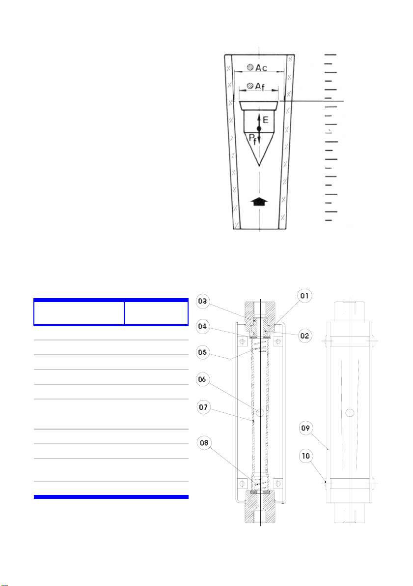
Working Principle
The flowmeter consists of a float inside a conical tube.
The rising flow pushes the float to an equilibrium point.
The area obtained between the float and the orifice is
proportional to the flow rate.
This type of measuring principle is known as variable
area.
The equilibrium point depends on :
− The float weight : Pf
− The fluid thrust : E
− The free flow area : Al
The area proportional to the flow rate will be:
where:
Ac = Flow measuring tube area
Af = Float area
Each position of the float corresponds to a flow rate
indicated on the scale printed on measuring tube.
n. Part Materials
1 Body EN 1.4404
2 M. Tube clamp EN 1.4404
3 O-ring NBR
4 End gasket NBR
5 Top spring EN 1.4401
6 Float
7 Measuring Tube Borosilicate Glass
8 Bottom spring EN 1.4401
9
10 Screw Nylon ®
Al = Ac - Af
EN 1.4404 /
Glass / Ceramic /
Transparent
protection
Metacryilate
Hostalen
Reading
line (see
3)
page
2
Page 4

RECEPTION
The flowmeter is supplied ready for installation and service.
The blocking elements that hold the float for transport should be removed before installation.
Turning the instrument up side down, check that the float moves freely in the tube.
INSTALLATION
The instrument must be installed taking into account the following:
The fluid inlet will be in the bottom of the flowmeter (the one nearest the scale’s minimum value).
The fluid outlet will be in the top of the flowmeter (the one nearest the scale’s maximum value).
It is very important that the position of the instrument is completely vertical, given that deviations of
about 5º– 10º can produce errors of about 10% of the reading.
Never open suddenly the regulating valve as this may cause the float to hit the glass tube
!
and break it.
FLOW RATE READING
The float determines the flow rate
measurement on the scale.
AC Shape ECG Shape
Forma AC
Forma ECG
Linea de lectura
Reading Line
For the different shapes of floats, the
readings must be taken at the height
shown in the drawing at the right.
CLEANING AND MAINTENANCE
Remove the 4 screws (10) and the transparent protection (9) to gain access inside the body (1).
Screw up the measuring tube clamp (2) into the body head (1), until the metering tube (7) is free.
Remove the metering tube (7), taking care that the top and bottom springs (8 and 5) don’t fall out.
Once the metering tube (7) is removed, withdraw the top and the bottom springs (8 and 5) and the
float (6). NOTE: The top spring is different from the bottom one and should not be interchanged.
Cleaning should be done using a soft brush (bottle brush or similar) to avoid scratching the
measuring tube.
The float should also be cleaned with a soft brush, never with metallic utensils which could scratch
it’s surface
To reassemble the instrument, inspect the gaskets (4) to see if they are in good working condition,
and if not, change them.
Put the bottom spring (8) in the measuring tube (7), insert the float and the top spring (5).
Assemble the measuring tube inside de body.
Screw down the measuring tube clamp (2) from the body head (1), until the tube is tight and th e
gaskets make a proper seal.
Put the transparent protection (9) in the body (1) and screw in the 4 screws (10).
3
Page 5

RECEPTION
The flowmeter is supplied ready for installation and service.
The blocking elements that hold the float for transport should be removed before installation.
Turning the instrument up side down, check that the float moves freely in the tube.
INSTALLATION
The instrument must be installed taking into account the following:
The fluid inlet will be in the bottom of the flowmeter (the one nearest the scale’s minimum value).
The fluid outlet will be in the top of the flowmeter (the one nearest the scale’s maximum value).
It is very important that the position of the instrument is completely vertical, given that deviations of
about 5º– 10º can produce errors of about 10% of the reading.
Never open suddenly the regulating valve as this may cause the float to hit the glass tube
!
and break it.
FLOW RATE READING
The float determines the flow rate
measurement on the scale.
AC Shape ECG Shape
Forma AC
Forma ECG
Linea de lectura
Reading Line
For the different shapes of floats, the
readings must be taken at the height
shown in the drawing at the right.
CLEANING AND MAINTENANCE
Remove the 4 screws (10) and the transparent protection (9) to gain access inside the body (1).
Screw up the measuring tube clamp (2) into the body head (1), until the metering tube (7) is free.
Remove the metering tube (7), taking care that the top and bottom springs (8 and 5) don’t fall out.
Once the metering tube (7) is removed, withdraw the top and the bottom springs (8 and 5) and the
float (6). NOTE: The top spring is different from the bottom one and should not be interchanged.
Cleaning should be done using a soft brush (bottle brush or similar) to avoid scratching the
measuring tube.
The float should also be cleaned with a soft brush, never with metallic utensils which could scratch
it’s surface
To reassemble the instrument, inspect the gaskets (4) to see if they are in good working condition,
and if not, change them.
Put the bottom spring (8) in the measuring tube (7), insert the float and the top spring (5).
Assemble the measuring tube inside de body.
Screw down the measuring tube clamp (2) from the body head (1), until the tube is tight and th e
gaskets make a proper seal.
Put the transparent protection (9) in the body (1) and screw in the 4 screws (10).
3
Page 6

Page 7

WARRANTY
Tecfluid S.A. GUARANTEES ALL ITS PRODUCTS FOR A PERIOD OF 24 MONTHS, after
consignment, against all defects in materials and workmanship.
This warranty does not cover failures which can be impu te d to misuse, use in an appli catio n dif fe ren t
to that specified in the or der, the result of service or modification b y un-authorized persons, bad
handling or accident.
This warranty is limited to cover the repair or replacement defective parts which have not been
damaged by misuse.
This warranty is limited to the repair of the equipment and all further and eventually following
damages are not covered by this warranty.
Any consignment of equipment to our factory or distributor must be previously authorised. The
consignment should be done with the equipment well packed, clean of any liquids, grease or
hazardous materials. Tecfluid S.A. will not accept any responsibility for damage done during
transport.
Together with the equipment, a note should be enclosed indicating the failure obs erved, the name,
address and telephone number of the sender.
TECFLUID, S.A.
Narcís Monturiol, 33
E-08960 Sant Just Desvern
Tel. + 34 933 724 511 - Fax + 34 934 734 449
E-mail: [email protected]
Internet: www.tecfluid.com
The technical data in this pamphlet is subject to modification without notification, if the technical innovations in the product or
manufacturing processes so require.
Page 8

 Loading...