

Page 1
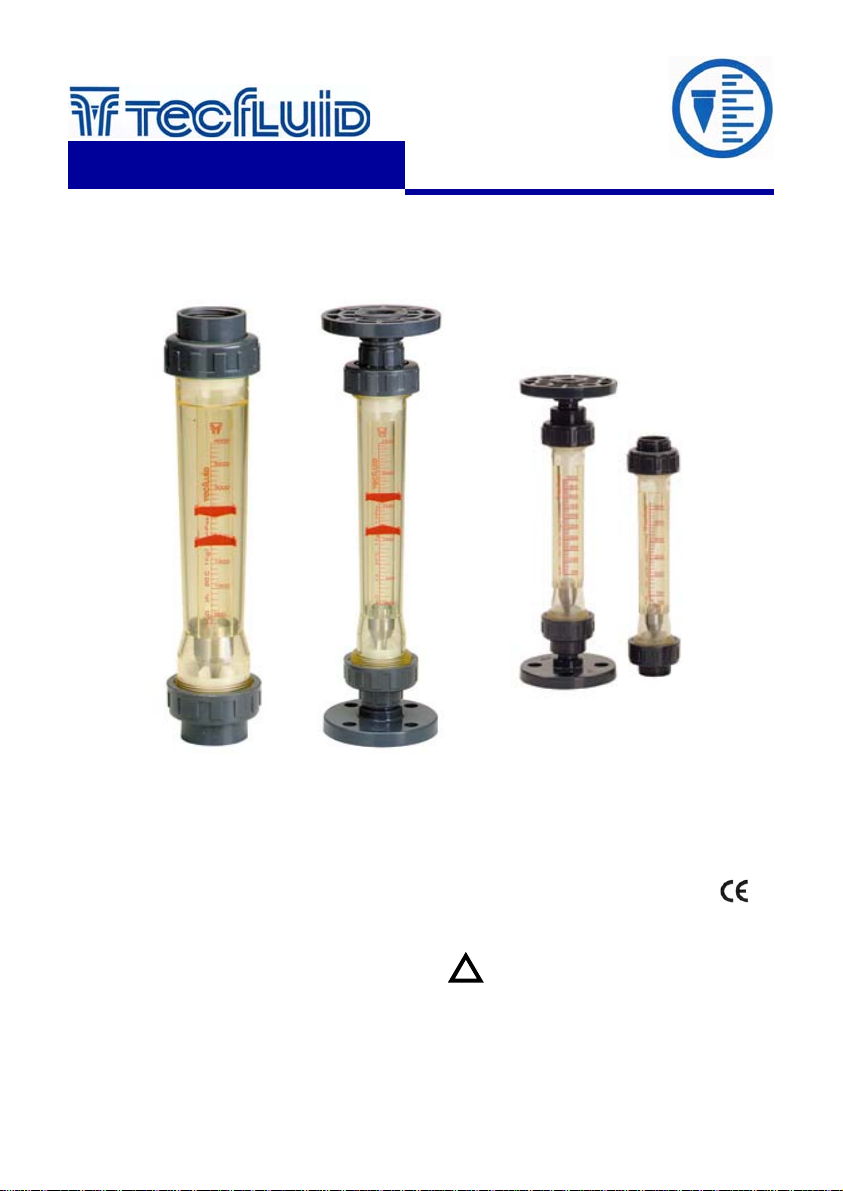
Variable area
flowmeters
instrumentation
for fluid s
Series
PT / PS / PTM / PSM
Instructions Manual
Technical Data
• Accuracy: Based on VDE / VDI 3513
- PT/PS ± 4% of full scale value
- PTM/PSM ± 6% of full scale value
• Material:
- PT/PTM Trogamid T
- PS/PSM: Polysulfphone
• Mounting: Vertical (Rising flow direction)
• Pipe fittings:
- PT-11/PS-31 BSP female thread
- PT-12/PS-32 DIN flanges
- PTM/PSM-01 BSP female thread
- PTM/PSM-02 DIN flanges
• Max. Working pressure:
from 8 to15 bar at 20 ºC depending on the tube
• Max.Fluid temperature: 0 ... +60ºC (Trogamid T)
0 ... +90ºC (Polysulphone)
C-MI-11 Rev.: 1
English Version
• Conforms with the Pressure
Equipment Directive 97/23/CE.
This equipment is considered as being a
!
pressure accessory and NOT a safety
accessory as defined in the 97/23/CE
directive, Article 1, paragraph 2.1.3.
0830
Page 2
Working principle
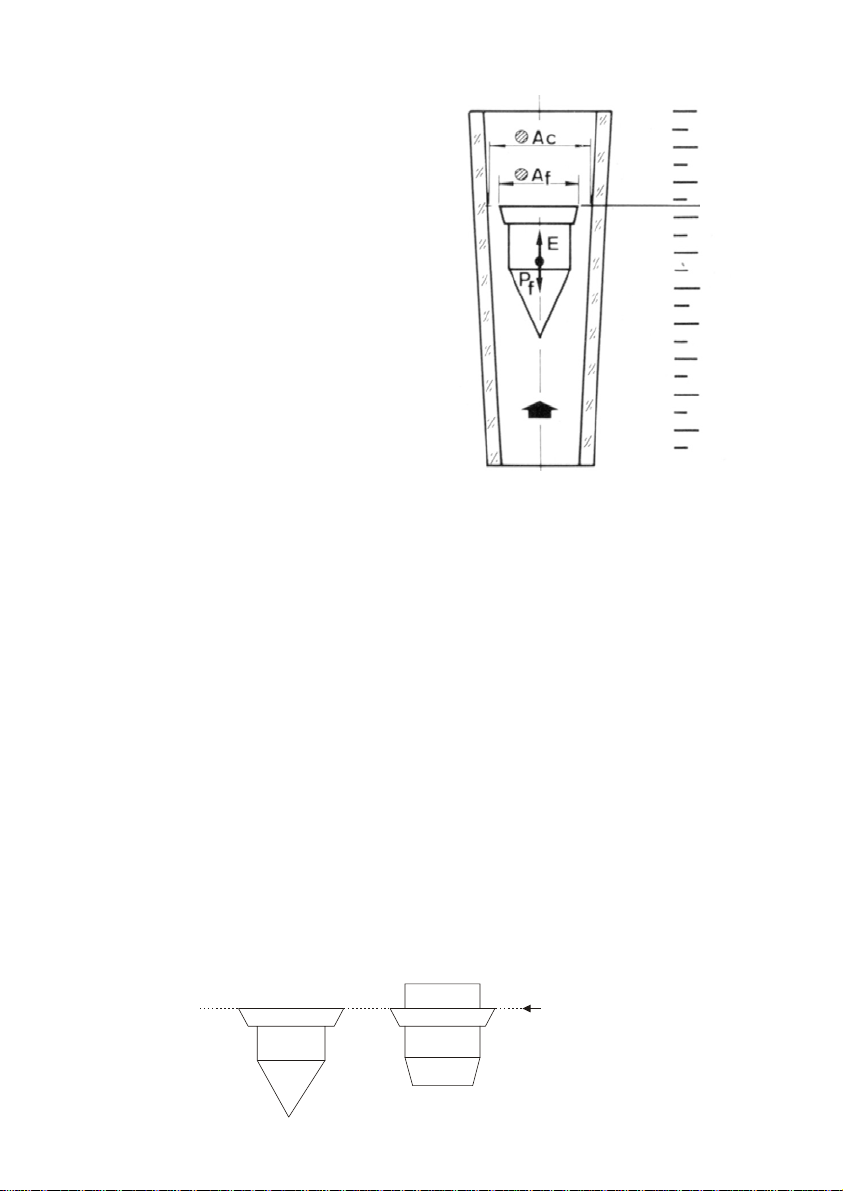
The flowmeter consists of a float inside a conical
tube. The rising flow pushes the float to an
equilibrium point. The area obtained between the
float and the orifice is proportional to the flow rate.
This type of measuring principle is known as
variable area.
The equilibrium point depends on :
− The float weight : Pf
− The fluid thrust : E
− The free flow area : Al
Reading
line
(See below)
The area proportional to the flow rate will be:
Al = Ac - Af
where:
Ac = Flow measuring tube area
Af = Float area
Each position of the float corresponds to a flow
rate indicated on the scale printed on measuring
tube.
RECEPTION
The flowmeter is supplied ready for installation and service.
The instrument is supplied packed for their protection during transport and storage. Likewise they
have blocking elements that should be removed before installation.
Turning the instrument up side down, check that the float moves freely up and do wn through the
whole length of the tube.
INSTALLATION
Before carrying out the installation, verify that the seals are made of a material that is suitable for
the fluid to be measured.
The instrument must be installed taking into account the following:
The fluid inlet will be in the bottom of the flowmeter (the one nearest the scale’s minimum value).
The fluid outlet will be in the top of the flowmeter (the one nearest the scale’s maximum value).
It is very important that the position of the instrument is completely vertical, given that deviations
of about 5º can produce errors of about 10% of the reading.
FLOW RATE READING
The float determines the flow rate measurement on the scale.
For the different shapes of floats, the readings must be taken at the height shown in the following
drawing.
Reading line
2
Page 3
CLEANING AND MAINTENANCE
For routine cleaning, normally it is sufficient to pass a so lution o f water and detergent t hrough th e
flowmeter.
If the float is obstructed or the tube is too dirty, the flowmeter must be removed from the line and
disassembled in order to clean the tube and the float.
Before remove it, close the supply of fluid to the flowmeter.
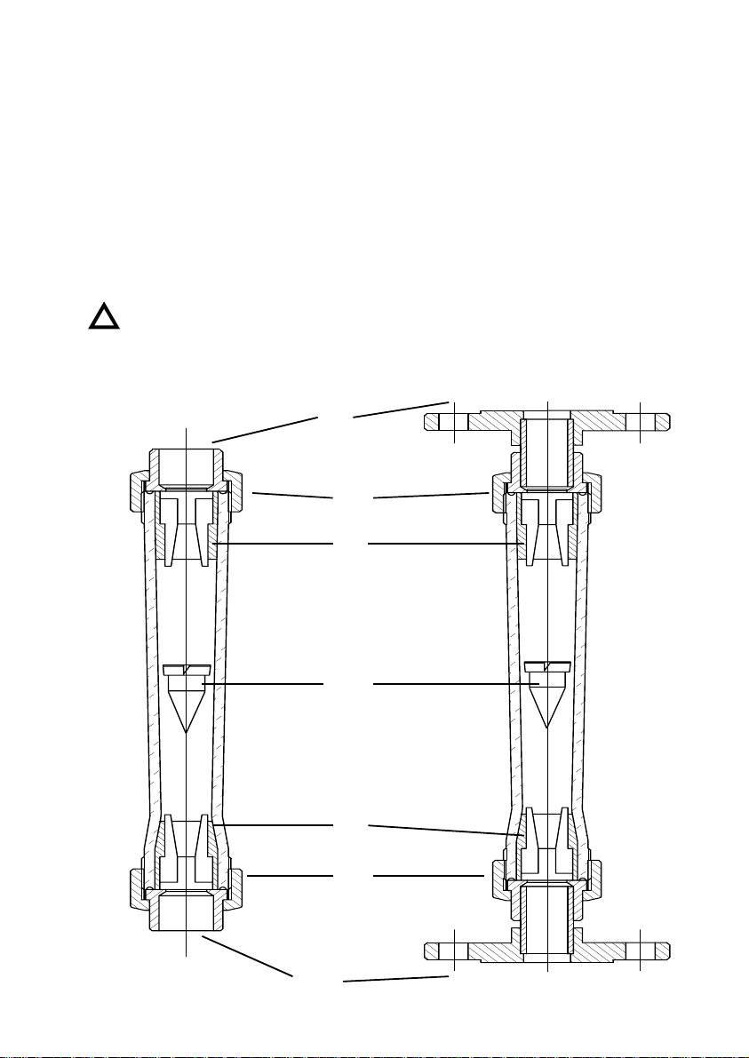
Remove the flowmeter from the line, by disconnecting the unit at the top and the bottom (1).
Remove the nuts (2) and the float stops (3).
Remove the float (4).
Now the tube and the float may be cleaned, using an appropriate detergent.
Be careful not to damage the tube when cleaning it. It is recommended to use a cloth.
Important: Never use ethyl alcohol or alcohol-based detergents for cleaning the tube.
There are a large variety of chemical agents that can damage the f lowmeter. For this
!
reason it is advisable to contact the manufacturer in case of doubt.
1
2
3
1
4
3
2
3
Page 4

The float must be cleaned with a soft brush, NEVER WITH METALLIC UTENSILS.
To assemble the unit follow the disassembly process in reverse. Insert the float so that the largest
diameter is always facing upwards. Before re-installing the flowmeter in the line, verify that the float
moves freely through the plastic tube.
REPLACING THE PLASTIC TUBE
To replace the plastic tube follow the process described for the disassembly, assembly and reinstallation of the flowmeter, changing the disassembled tube.
WARRANTY
Tecfluid S.A. GUARANTEES ALL ITS PRODUCTS FOR A PERIOD OF 24 MONTHS, after
consignment, against all defects in materials and workmanship.
This warranty does not cover failures which can be i mputed to misuse, use in an ap plication diff erent
to that specified in the order, the result of serv ice or modification by un-authorized persons, bad
handling or accident.
This warranty is limited to cover the repair or replacement defective parts which have not been
damaged by misuse.
This warranty is limited to the repair of the equipment and all further and eventually following
damages are not covered by this warranty.
Any consignment of equipment to our factory or distributor must be previously authorised. The
consignment should be done with the equipment well packed, clean of any liquids, grease or
hazardous materials. Tecfluid S.A. will not accept any responsibility for damage done during
transport.
Together with the equipment, a note should be enc losed indicating the failure observed, th e name,
address and telephone number of the sender.
TECFLUID, S.A.
Narcís Monturiol, 33
E-08960 Sant Just Desvern
Tel. + 34 93 3724511 - Fax + 34 93 4734449
E-mail: [email protected]
Internet: www.tecfluid.com
The technical data in this pamphlet is subject to modification without notification, if the technical innovations in the product or
manufacturing processes so require.
 Loading...