

Page 1
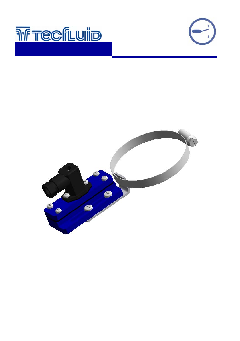
LT-APR
Limit switch
instrumentation
for fluids
Instructions Manual
R-MI-LTAPR Rev.: 2 English version
Page 2
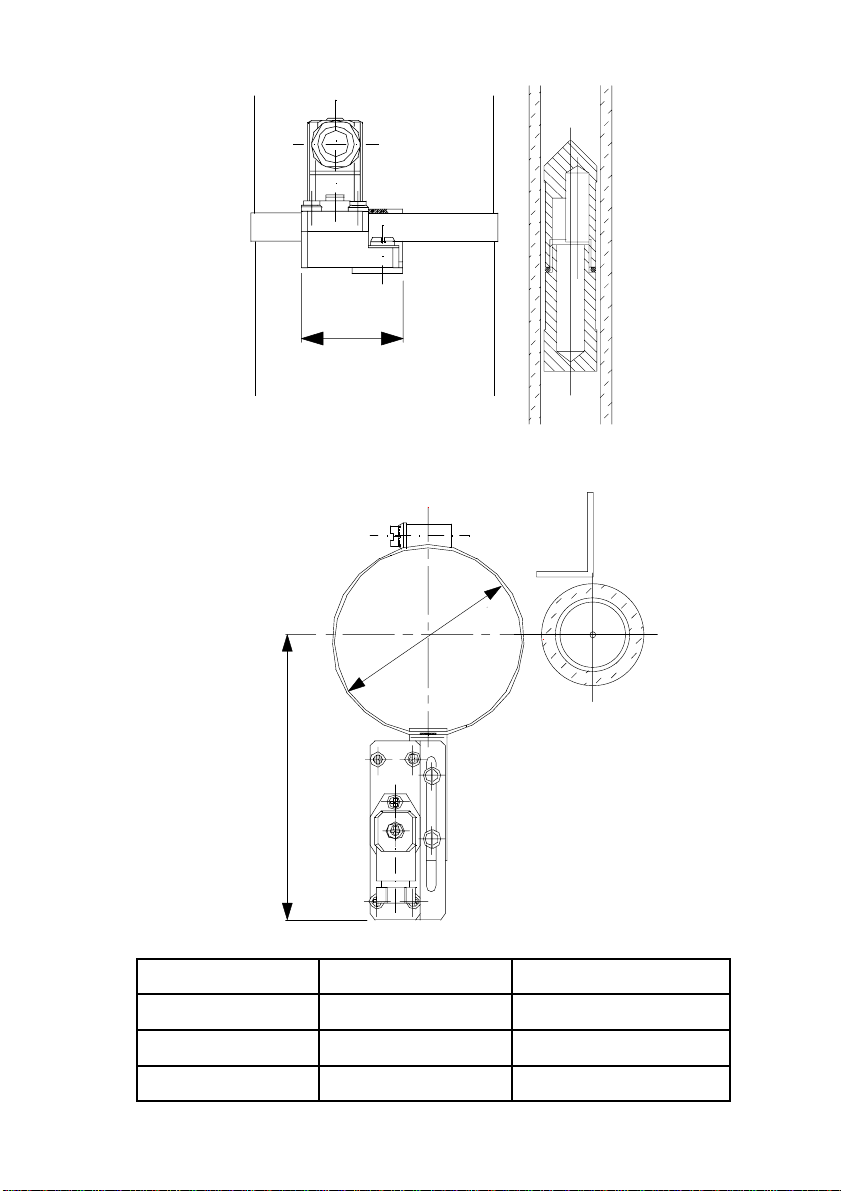
DIMENSIONS
31
∅
D
L
Model ØD = Ømin ... Ømax Lenght L
LT-APR3 23 ... 35 mm 90 mm (for Ø 32)
LT-APR6 50 ... 70 mm 105 mm (for Ø 60.3 & Ø 63 )
LT-APR7 60 ... 80 mm 110 mm (for Ø 73)
2
Page 3
OPERATION
The LT-APR series are limit switches based on a bi-stable SPDT reed.
The reed is activated by the magnetic field from the float of a level indicator of the LT series.
TECHNICAL DATA
• Connector with PG7 cable gland. Soldered connections.
• Polyamide housing with IP65 ingress protection.
• Maximum working current: 0.5 A.
• Maximum working voltage: 250 VAC.
• Maximum power: 60 VA.
• Temperature range: -10, +70ºC
• Conforms with the Directive 73/23/EEC
CONNECTION
31
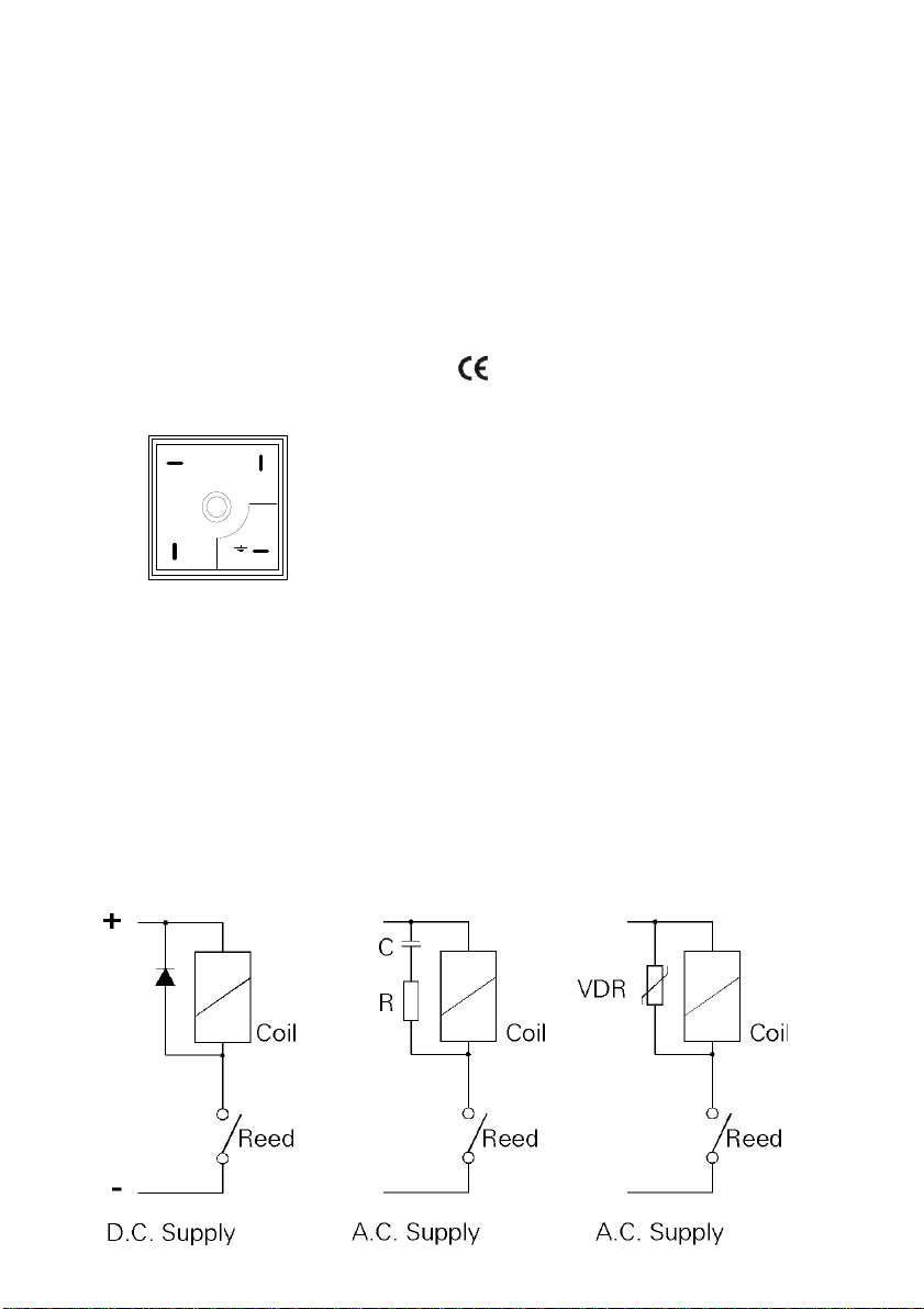
In the female connector (A): (see the following page)
Terminal 1: Common
Terminal 2: NO
2
Terminal 3: NC
Earth terminal: No connection
Terminal 2 is the normally open conta ct when the floa t is below the leve l sw itch .
For the electrical installation it is recommended to use multiple c onductor cables to guarantee the
instrument will stay water tight.
The connector admits cable diameters from of 4.5 to 7 mm.
The electrical installation should provide a fuse or circuit breaker to protect the reed switch from
overloads.
When installing the connector, make sure that the cable gland closes over the cable and that the
connector with the rubber seal is well screwed down to maintain the IP65 rating.
Make sure that the contact rating is not exceeded. If high loads are to be switched, use an auxiliary
relay.
When using inductive loads, such as relays or electro-valve coils, surge arresters should be installed
to protect the reed contacts.
With a DC su p ply, a diod e should be c o nnect e d as sh o wn.
3
Page 4
For an AC supply, a RC circuit can be used as shown, although a varistor (VDR) is better and is
easier to select the right value. The VDR should have a breakdown voltage greater than 1.5 times
the rms voltage. The standard varistor ratings specify the rms working voltage for the varistor, for
example a S05K25 varistor will be for 25 Vrms working and will have a breakdown voltage of 39 V
at 1 mA.
MOUNTING
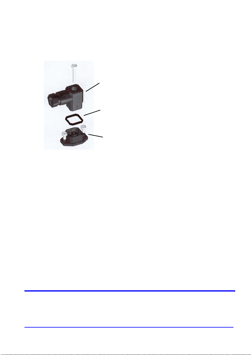
A
Once the electrical connection has been made
and the cable gland has been tightened, mount
the female connector (A) on the male base (C),
placing the seal (B) between the two pieces.
B
To fix the level switch in its position on the
level, completely unscrew the hose band (D)
and open it. With the hose band open situate
the level switch on the float tube and close the
hose band over the tube.
C
Situate the level switch at the required height
and tighten the hose band.
WARRANTY
Tecfluid S.A. GUARANTEES ALL ITS PRODUCTS FOR A PERIOD OF 24 MONTHS, after
consignment, against all defects in materials and workmanship.
This warranty does not cover failu res which can be imp uted to mis use, use in an application different
to that specified in the order, the result of service or modification by un-authorized persons, bad
handling or accident.
This warranty is limited to cover the repair or replacement defective parts which have not been
damaged by misuse.
This warranty is limited to the repair of the equipment and all further and eventually following
damages are not covered by this warranty.
Any consignment of equipment to our factory or distributor must be previously authorised. The
consignment should be done with the equipment well packed, clean of any liquids, grease or
hazardous materials. Tecfluid S.A. will not accept any responsibility for damage done during
transport.
Together with the equipmen t, a note should be enclosed indicating the failure observ ed, the name,
address and telephone number of the sender.
TECFLUID, S.A.
Narcís Monturiol, 33
E-08960 Sant Just Desvern
Tel. + 34 93 3724511 - Fax + 34 93 4734449
E-mail: [email protected]
Internet: www.tecfluid.com
The technical data in this document is subject to modification without notification, if the technical innovations in the product or
manufacturing processes so require.
 Loading...