

Page 1
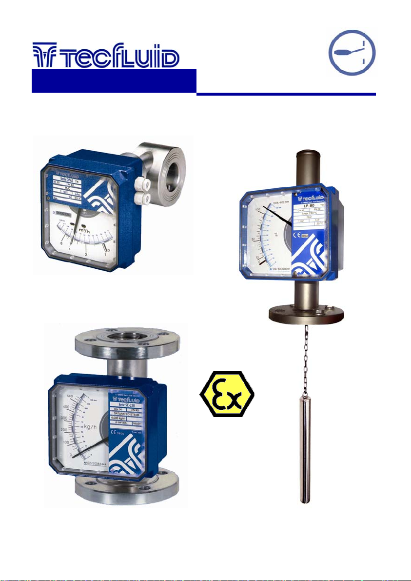
Limit switches
AMD & AMM
instrumentation
for fluids
For Series
SC / SM / DP / LP
Instructions manual
R-MI-AMDAMMSC/DP Rev.: 0 English version
Page 2

TABLE OF CONTENTS
LIMIT SWITCH AMD
1 INTRODUCTION ..................................................................................... 3
2 OPERATION ........................................................................................... 3
3 SWITCHING POINT ADJUSTMENT ...................................................... 3
4 ELECTRICAL CONNECTION ….......................................………........... 3
5 MAINTENANCE ...................................................................................... 4
6 TECHNICAL CHARACTERISTICS ........................................................ 5
7 SAFETY CHARACTERISTICS .........................................………........... 5
LIMIT SWITCH AMM
1 INTRODUCTION ..................................................................................... 6
2 SWITCHING POINT ADJUSTMENT ...................................................... 6
3 ELECTRICAL CONNECTION ……...................................………........... 7
4 TECHNICAL CHARACTERISTICS ........................................................ 7
2
Page 3
LIMIT SWITCH AMD
1 INTRODUCTION
The AMD limit switch can be used to generate an alarm or an operation when the flow rate
or the level that the instrument is measuring reaches a preset value on the scale plate.
The AMD limit switch consists of a NAMUR slot type inductive sensor, that is actuated by a
vane. Given that there is no physical contact in the operation, the limit switch has no
influence on the indicator needle movement.
An instrument can be equipped with one or two sensors, depending on the number of
points to be detected. A NAMUR amplifier with a relay output can be supplied as an option.
2 OPERATION
The indicator needle moves together with the vane mounted on its shaft. When the vane
enters into the slot of the sensor, the limit switch changes its state.
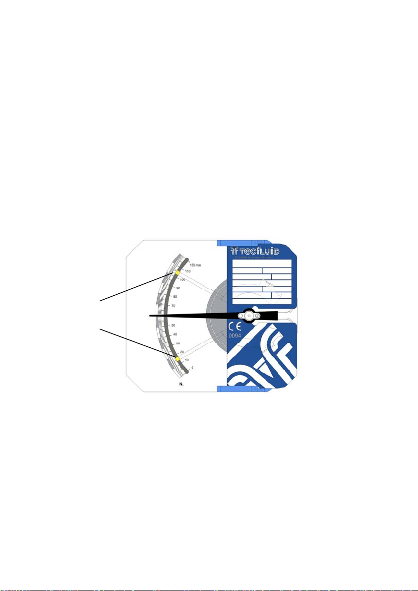
The sensor, is mounted on a support which includes a needle that indicates the switching
position. The needle, that is below the scale plate, can be seen through the scale slot.
Switching
points
3 SWITCHING POINT ADJUSTMENT
To gain access to the limit switch inside the indicator housing, remove the front cover held
by four M5 x 16 DIN 912 screws, using a 4 mm Allen key. The circular fixing nuts of the
switching point are in the rear part of the indicator needle.
To move the limit switch needle, the circular fixing nuts have to be slightly loosen by
turning them to the left, without removing the scale plate (see the figure on the next page).
After that, place the limit switch needle in the required scale value, and fix it again with the
screw.
As standard, when the instrument has only one AMD, it comes configured as a minimum
limit switch.
4 ELECTRICAL CONNECTION
To gain access to the electrical terminal block, the scale plate must be removed. To do
this, slide it to the left by the guide until it be free.
3
Page 4
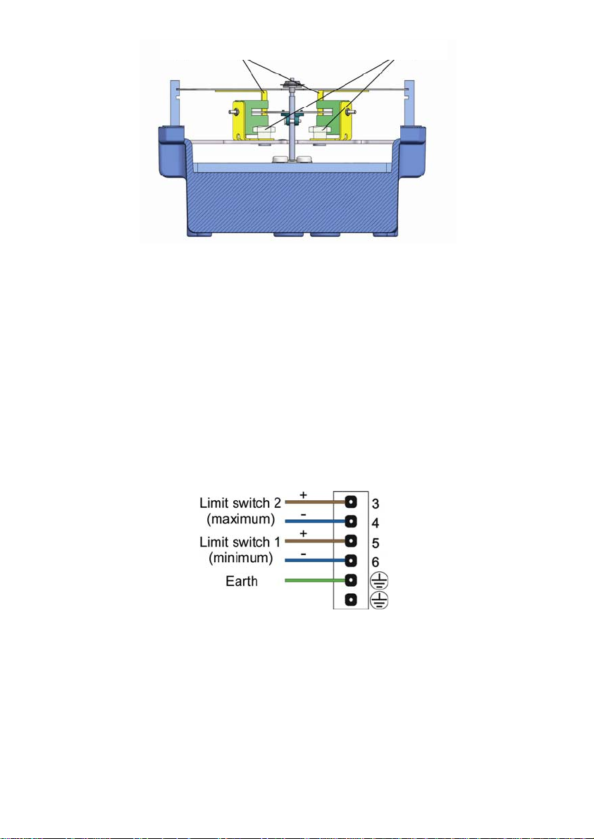
Limit switch needles Fixing nuts
In order to make the electrical connection of the instrument, the limit switch has a screw
terminal strip.
For the electrical installation it is recommended to use multiple conductor cables with
individual cable sections in the order of 0.25 to 0.5 mm
connect. Loose cables should not be used given that they can affect the seal of the cable
glands. It is better to maintain the mains cables separated from the cables with low level
signals.
Before starting the installation, check that the cable glands are the right size for the cables
to be used, this will guarantee the instrument will stay watertight. The supplied PG11
cable glands are for cables with outside diameters between 6 mm and 10 mm.
Peel the outside insulation to free the inner cables. It is recommended to tin the ends of
the wires to avoid loose ends. Next, feed the cables through the cable glands, and
connect to the corresponding screw terminals. Last, tighten up the cable glands so that
they maintain their degree of protection (IP). The numbering of the terminals is given on
the printed circuit board.
5 MAINTENANCE
Electrical verification of the limit switch
If you have the NAMUR amplifier, power it on and check that the voltage at the terminals
+ and - is over 7.5 V when the vane is in the slot.
Connect a multimeter with the scale in DC mA, in series with the terminal +.
Verify that the current is less than 1 mA when the vane is in the slot, and more than 3 mA
when the vane is out of the slot.
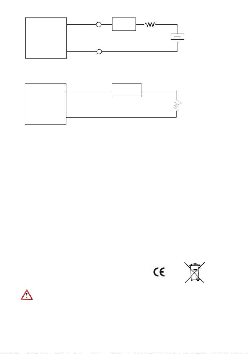
If you don’t have the NAMUR amplifier, the current can be checked using the following
circuit diagram:
2
in order to make it easier to
4
Page 5
AMD
+
-
+
+
1 k
+
9 V Battery
(8.2 V Nominal for
NAMUR )
-
Multimeter
mA
-
-
If you don’t have the AMD sensor, the operation of the amplifier can be checked using the following circuit diagram:
Amplifier
+
NAMUR
connection
+
Multimeter
mA
-
Potentiometer 20 k
-
With the potentiometer we modify the current of the NAMUR amplifier. The switching point must be
between 1.2 mA and 2.1 mA. That is, with the current below 1,2 mA the output relay must have a
state and above 2,1 mA the output relay must have the other state.
6 TECHNICAL CHARACTERISTICS
Nominal voltage 8 V
Working voltage 5 ... 25 V
Power supply internal resistance 1 k
Current with the vane into the slot 1 mA
Current with the vane out of the slot ≥ 3 mA
Standard: DIN EN 60947-5-6 (NAMUR)
Ambient temperature -25 ... +100 ºC
Type of protection IP67
Internal Inductance 250 µH
Internal Capacitance 50 nF
Marking II 1 G EEx ia IIC T6
Certificate PTB 99 ATEX 2219 X
7 SAFETY CHARACTERISTICS
Conforms to the Directive 2004/108/CE
Conforms to the Directive 2002/96/CE
Conforms to the Directive 94/9/CE
Given that this instrument is group II, it is intended for use in places likely to become
endangered by explosive atmospheres, but not in mines.
The category is 1G, that is, it is intended for use in areas in which explosive atmospheres
caused by mixtures of air and gases, vapours or mists are present continuously, for long
periods or frequently.
The front window must always be cleaned with a damp cloth, in order to avoid
electrostatic discharges.
5
Page 6
LIMIT SWITCH AMM
1 INTRODUCTION
The AMM limit switch can be used to generate an alarm or an operation when the flow rate
or the level that the instrument is measuring reaches a preset value on the scale plate.
It consists of a micro-switch driven by a cam mounted on the indicating needle.
An instrument can be equipped with one or two micro-switches, depending on the number
of points to be detected.
2 SWITCHING POINT ADJUSTMENT
To gain access to the limit switch inside the indicator housing, remove the front cover held
by four M5 x 16 DIN 912 screws, using a 4 mm Allen key. After that, remove the scale
plate sliding it to the left by the guide until it be free.
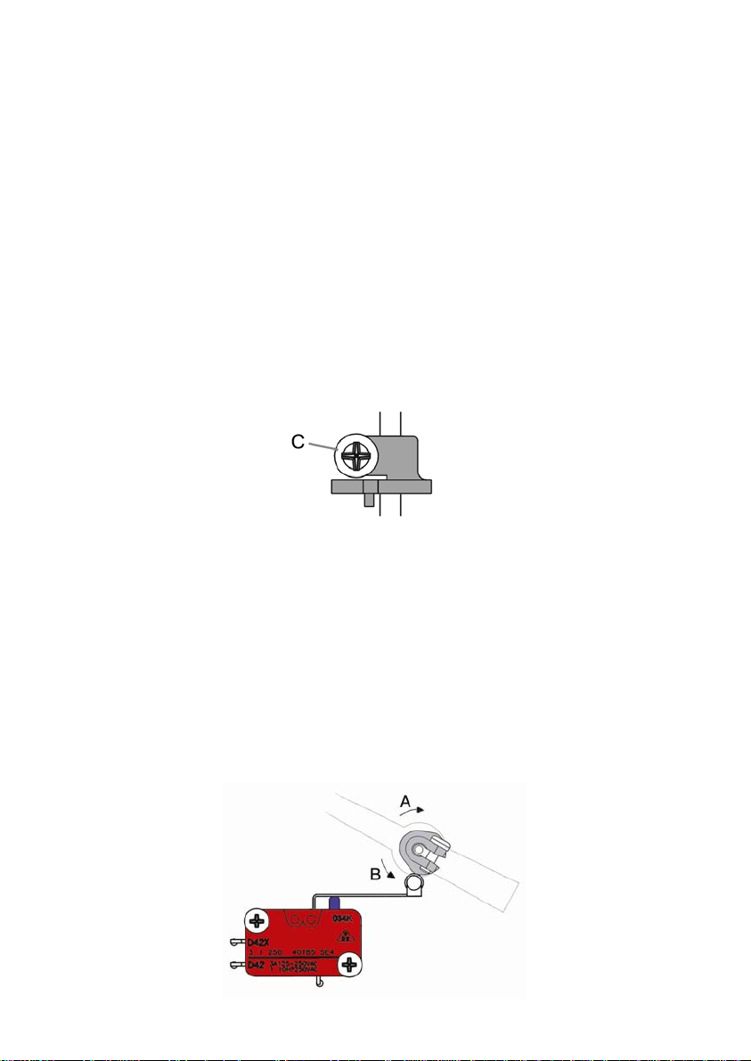
To adjust the switching point, loosen slightly the cam’s grub screw (C) and turn the cam on
the shaft until the required switching point is achieved.
Screw: DIN7981 B-2.2 x 9.5
To turn the cam on the shaft, do not hold the shaft by the indicating needle, as this may
move the needle on the shaft. The shaft should be held directly.
For the SC BD, SC DES, DP BD, DP DES SM and LP series, if the cam is turned in the “A”
direction, the acting point will move away from the zero point of the scale. If the cam is
turned in the “B” direction, the acting point will move towards the zero point of the scale.
For the SC ED, SC DAB, DP ED and DP DAB series, if the cam is turned in the “A”
direction, the acting point will move towards to the zero point of the scale. If the cam is
turned in the “B” direction, the acting point will move away from the zero point of the scale.
Once the cam is in its position making sure that the cam rests on the follower of the microswitch lever, and the grub screw (C) has been tightened, the correct working of the limit
switch should be verified by turning the indicating needle shaft and checking the switching
at the required point.
Cam shown acting on
the micro-switch
lever.
6
Page 7
3 ELECTRICAL CONNECTION
To gain access to the electrical terminal block, the scale plate must be removed. To do
this, slide it to the left by the guide until it be free.
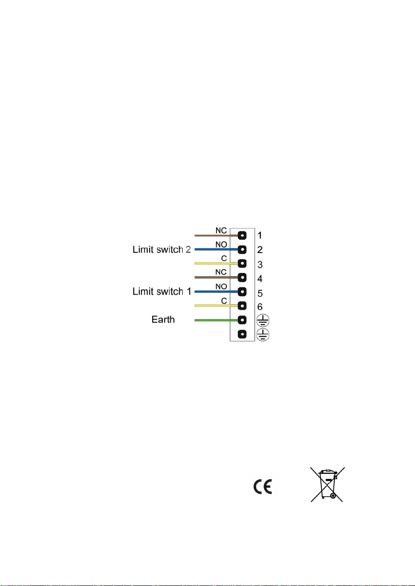
In order to make the electrical connection of the instrument, the limit switch has a screw
terminal strip.
For the electrical installation it is recommended to use multiple conductor cables with
individual cable sections in the order of 0.25 to 0.5 mm
connect. Loose cables should not be used given that they can affect the seal of the cable
glands. It is better to maintain the mains cables separated from the cables with low level
signals.
Before starting the installation, check that the cable glands are the right size for the cables
to be used, this will guarantee the instrument will stay watertight. The PG11 cable glands
used are for cables with outside diameters between 6 mm and 10 mm.
Peel the outside insulation to free the inner cables. It is recommended to tin the ends of
the wires to avoid loose ends. Next, feed the cables through the cable glands, and connect
to the corresponding screw terminals. Last, tighten up the cable glands so that they
maintain their degree of protection (IP). The numbering of the terminals is given on the
printed circuit board.
2
in order to make it easier to
NOTE: The contacts are defined with the cam WHEN NO acting on the micro-switch
lever).
4 TECHNICAL CHARACTERISTICS
Maximum switching voltage 250 VAC
Maximum switching current 3 A
Potential free SPDT contacts
Ambient temperature -25 ... +100 ºC
Type of protection IP67
Conforms to the Directive 2004/108/CE
Conforms to the Directive 2002/96/CE
Conforms to the Directive 2006/95/CE
7
Page 8

WARRANTY
Tecfluid S.A. GUARANTEES ALL ITS PRODUCTS FOR A PERIOD OF 24 MONTHS, after
consignment, against all defects in materials and workmanship.
This warranty does not cover failures which can be imputed to misuse, use in an application different
to that specified in the order, the result of service or modification by un-authorized persons, bad
handling or accident.
This warranty is limited to cover the repair or replacement defective parts which have not been
damaged by misuse.
This warranty is limited to the repair of the equipment and all further and eventually following
damages are not covered by this warranty.
Any consignment of equipment to our factory or distributor must be previously authorised. The
consignment should be done with the equipment well packed, clean of any liquids, grease or
hazardous materials.
Together with the equipment, a note should be enclosed indicating the failure observed, the name,
address and telephone number of the sender.
SHIPPING
In the event of damages during shipping, claim directly to the agency over a period of less than 24
hours. Tecfluid is not responsible for any damage caused during the shipment of material.
TECFLUID, S.A.
Narcís Monturiol, 33
E-08960 Sant Just Desvern
Tel. + 34 93 3724511 - Fax + 34 93 4734449
E-mail: [email protected]
Internet: www.tecfluid.com
The technical data in this document is subject to modification without notification, if the technical innovations in the product or
manufacturing processes so require.
 Loading...