

Page 1
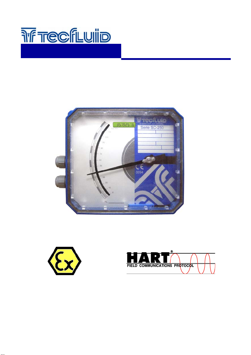
Transmitters HALLTEC V
TH5, TH5T, TH5H, TH5TH
instrumentation
for fluids
For Series
SC / SCH / SCV / SM / DP / LP
Instructions Manual
R-MI-TH5 Rev.: 1 English version
Page 2

TABLE OF CONTENTS
1 INTRODUCTION ................................................................................... 3
2 MODELS ............................................................................................... 3
2.1 TH5 ........................................................................................... 3
2.2 TH5H ......................................................................................... 3
2.3 TH5T and TH5TH ...................................................................... 3
3 ELECTRICAL CONNECTION .............................................................. 3
3.1 Power supply and analog output .......................................... 4
3.2 Pulse output and reset ........................................................... 4
TM
3.3 HART
4 ADDITIONAL FUNCTIONS WITH HART
TM
5 HART
COMMUNICATION CHARACTERISTICS ….......................... 6
transmitters ............................................................. 5
TM
COMMUNICATION ........ 6
6 ”WRITE PROTECT” ............................................................................ 7
7 MAINTENANCE ................................................................................... 7
8 4 WIRE CONNECTION ………............................................................. 8
9 LP SERIES ………………...…............................................................... 8
10 TECHNICAL CHARACTERISTICS ....................................................... 8
10.1 Power supply .......................................................................... 8
10.2 Outputs ................................................................................... 8
10.3 General characteristics .......................................................... 9
10.4 Safety characteristics ............................................................. 9
11 ADDITIONAL INSTRUCTIONS FOR THE ATEX VERSION ................ 9
11.1 Non metallic parts .................................................................. 9
11.2 Facilities connecting conductive parts to earth .................. 9
11.3 Technical characteristics of the Exi version ....................... 10
11.4 Marking .................................................................................... 10
11.5 Exi parameters ........................................................................ 11
12 TROUBLESHOOTING .......................................................................... 11
2
Page 3
1 INTRODUCTION
The Halltec V transmitter is an electronic position transducer with a microprocessor. The
instrument uses the Hall effect to capture the field of a magnet. This signal, after the microcontroller processing, is converted to a current signal of 4-20 mA in a 2 wire loop. This
signal is proportional to the flow rate.
2 MODELS
2.1 TH5
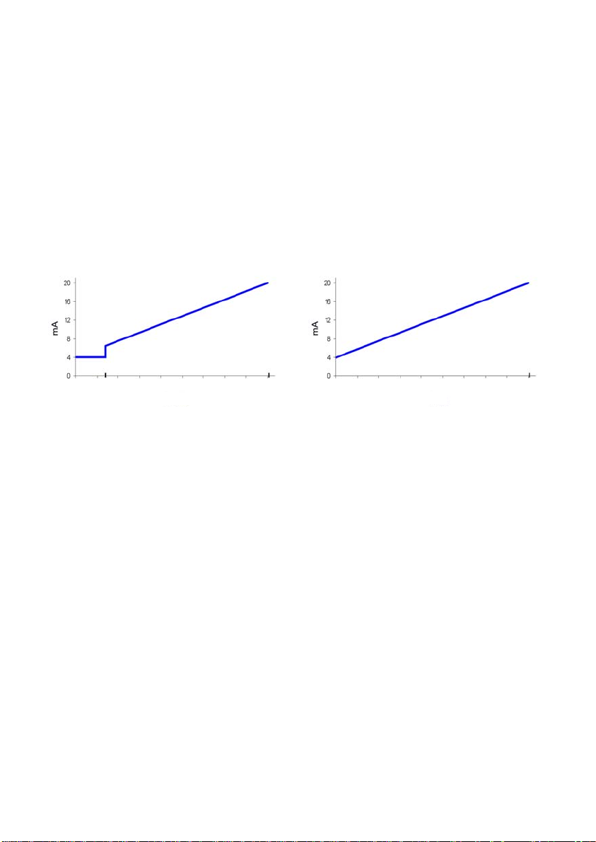
It is a 4 to 20 mA transmitter proportional to flow rate that incorporates a synchronized
pulse output. 4 mA corresponds to beginning of the scale. 20 mA corresponds to full scale.
Between the beginning of the scale and the first point of the scale the analog output is
constant at 4 mA, to avoid false readings of flow rate.
In the case of level measurement (LP series), the current range corresponds to the scale
at all the points.
First point of
the scale
Flow rate
Last point of
the scale
Level
1. Example: Response of the TH5 transmitter
2.2 TH5H
TM
It is a TH5 transmitter that incorporates HART
protocol compatibility. With this protocol
the user can change the measuring range of the 4-20 mA loop, and data like flow rate and
accumulated volume, with its associated measuring units.
2.3 TH5T and TH5TH
They are the equivalent models to those of the sections 2.1 and 2.2, but in addition they
include a 8-digit totalizer (7 entire numbers and 1 decimal).
3 ELECTRICAL CONNECTION
For the electrical connection, the Halltec V has a screw terminal strip.
For the electrical installation it is recommended to use multiple conductor cables with
individual cable sections in the order of 0.25 to 0.5 mm
2
in order to make it easier to
connect.
A twisted pair wiring should be used to avoid electrical interferences in the 4-20 mA loop.
In some instances, shielded cable may be necessary.
Before starting the installation, check that the cable glands are the right size for the cables
to be used, this will guarantee the instrument will stay watertight. The cable glands used
are for cables with outside diameters between 6 mm and 10 mm.
Peel the outside insulation to free the inner cables. It is recommended to tin the ends of
the wires to avoid loose ends. Pass the cables through the cable glands and screw down
in the corresponding positions of the terminal strip. Once the wiring is finished make sure
that the cables are well gripped by the cable glands to maintain the degree of protection.
Last point of
the scale
3
Page 4
The cable glands must be always closed. Entry of dust or some types of vapors can
damage the internal system of bearings and therefore the equipment.
Before connecting the power supply, you must be sure that the supply voltage is the
correct for the installation. The power supply voltage is indicated on the label of the
transmitter.
To help in the wiring of the equipment, the description of the terminals is marked on the
printed circuit next to the terminal strip.
3.1 Power supply and analog output
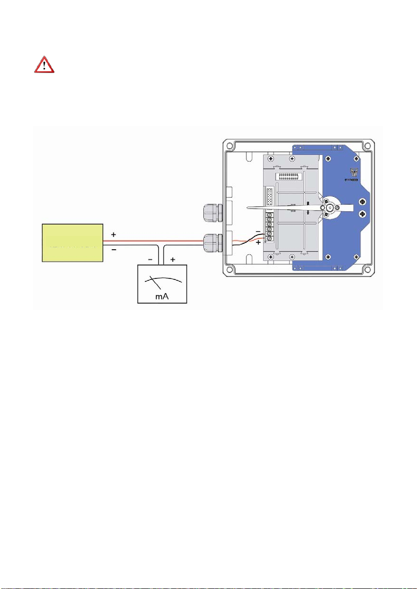
12 to 36 VDC
The connection is made in the terminal block. The positive terminal of the power supply is
connected to the position + and the positive terminal of the load in the position -. The
negative terminals of the power supply and the load are connected together. The
instrument works in a 2-wire system, that is, the supply and signal line is the same. It is
recommended to use a twisted pair wiring or shielded cable to avoid interferences in the
current loop.
3.2 Pulse output and reset
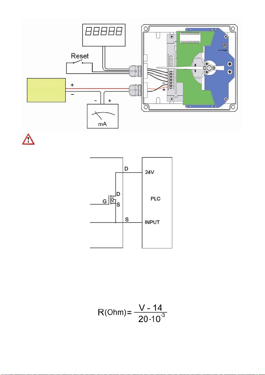
The pulse output is connected in the positions D and S of the terminal block. The output is
an N channel MOSFET isolated from the rest of the circuit and potential free. The S
terminal is the source and the D terminal is the drain.
The lower terminals marked as RESET are a reset input for the totalizer. It can be
connected a normally open potential free contact. It is important that the contact works
well with low level signals, to avoid noise effects.
4
Page 5
Volume
12 to 36 VDC
Note: The reset terminals are not isolated from the rest of the circuit. They may not be
connected to other equipment.
Example of the connection of the pulse output to a PLC
TM
3.3 HART
In the case of a HART
transmitters
TM
transmitter, an external resistor (R ext.) must be included. Its
minimum value will be 200 and the maximum value will depend on the power supply as
follows, being the power supply voltage V, 18 VDC minimum.
5
Page 6
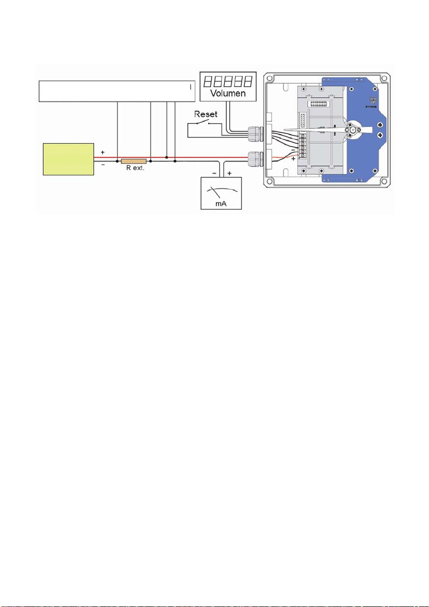
In order to establish HART
with a HART
TM
modem, in one of the points indicated in the following figure.
TM
communication, it is necessary to connect a terminal or PC
Possible points of connection of a HARTTM
terminal or a PC with a HART
18 to 36 VDC
4 ADDITIONAL FUNCTIONS WITH HART
The TH5H and TH5TH transmitters have a MODEM for HART
TM
modem
TM
COMMUNICATION
TM
communication.
By means of the implemented commands, the user can obtain the following information:
Flow rate value in real units
Totalizer value in real units (even if the equipment does not have a display).
Note: The units of flow rate can be changed and they can be different from those of the
scale of the instrument. Also, the units of flow rate and totalized volume, can be different.
Reset or writing of a totalizer value.
Change of beginning and end of scale of the current loop (a transmitter without
HART
TM
communication has always the beginning of scale at the zero point and
the end of scale at the maximum point of the scale plate).
Possibility of writing tags and messages into the instrument.
5 HART
TM
COMMUNICATION CHARACTERISTICS
The detail of the characteristics with respect to the HART
TM
communication are available
in the corresponding “Field Device Specification” document.
6
Page 7

Resume of the principal communication characteristics:
Manufacturer, Model and Revision Tecfluid S.A., TH5H, Rev. 0
Device type Transmitter
HART revision 6.0
Device Description available No
Number and type of sensors 1
Number and type of actuators 0
Number and type of host side signals 1, 4 – 20 mA analogic
Number of Device Variables 2
Number of Dynamic Variables 1
Mappable Dynamic Variables No
Number of Common Practice Commands 12
Number of Device Specific Commands 2
Bits of Additional Device Status 12
Alternative working modes? No
Burst mode? No
Write Protection? Yes
Electrical characteristics referred to the analog loop and communications:
Reception impedance
Rx > 3,3 MΩ
Cx < 1000 pF
6 “WRITE PROTECT”.
The instrument has a jumper that can be used to avoid changes in the configuration.
When the jumper is connected the instrument can be configured via HART
jumper is removed, “Write Protect” is activated for HART
TM
, thus avoiding any changes in
the configuration.
7 MAINTENANCE
No special maintenance is required.
TM
. When the
7
Page 8
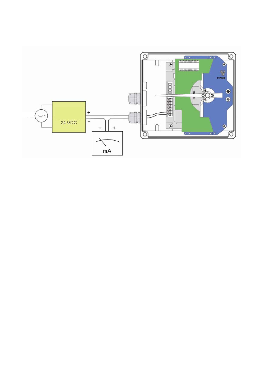
8 4 WIRE CONNECTION
If Direct Current power supply for the transmitter is not available in the installation, it will
be necessary to incorporate an additional power supply as in the following figure.
Mains
Power
supply
9 LP SERIES
Since LP series are level measuring instruments, they will be available only with TH5 and
TH5H models.
For HART
TM
communication, the measuring units of the primary variable (PV) will be a
percentage (%), and the value of this variable will indicate the percentage of level respect
to the instrument scale.
10 TECHNICAL CHARACTERISTICS
10.1 Power supply
2 wire.
Minimum voltage (TH5 y TH5T): 0.02 Z + 12 (Volt) (Z is the load in the current
The minimum value is 12 VDC for Z=0 Ohm.
Minimum voltage (TH5H y TH5TH): 0..02 (Z+Rext) + 14 (Volt) (Z is the load in the
The minimum value is 18 VDC for Z=0 Ohm and
Maximum voltage: 36 VDC (for the Ex version see point 11.3)
Consumption: maximum 20 mA
10.2 Outputs
Analog output: 4 - 20 mA, factory calibrated
Maximum load in the 4-20 loop: 1,1 k (at 36 VDC supply voltage)
Pulse output: MOSFET N channel potential free I
loop in Ohm).
current loop in Ohm).
Rext=200 Ohm.
(for Ex version see point 11.3)
: 200 mA
max
8
Page 9
Maximum frequency: 2 Hz.
Pulse duration: Aprox. 250 ms.
Totalizer: 8 digits. (7 + one decimal. Reset by means of
10.3 General characteristics
Housing ingress protection: IP65
Cable gland: PG11 or M16
Ambient temperature: -5 - +70 ºC (for Ex version see point 11.3)
Precision (analog output respect
the magnetic field): < 0.6 %
10.4 Safety characteristics
This material conforms with the following directives:
2004/108/EC Electromagnetic Compatibility.
2002/96/EC Waste electrical and electronic equipment.
11 ADDITIONAL INSTRUCTIONS FOR THE ATEX VERSION
This chapter only applies to equipment intended for use in explosive atmospheres.
These equipment conform with the directive 94/9/CE (Equipment and protective systems
intended for use in potentially explosive atmospheres) as is indicated in the EC-type
examination certificate LOM 09ATEX2087 X and in its marking.
Given that this instrument is group II, it is intended for use in places likely to become
endangered by explosive atmospheres, but not in mines.
The category is 1GD, that is, it is intended for use in areas in which explosive
atmospheres caused by mixtures of air and gases, vapours, mists or dust are present
continuously, for long periods or frequently.
11.1 Non metallic parts
potential free contact).
WARNING: POTENTIAL RISK OF ELECTROSTATIC CHARGE.
The front of the apparatus consists of a transparent plastic window in order to let the user
see the position of the pointer on the scale.
Since the danger of ignition by electrostatic discharge when rubbing this window can not
be avoided, the instrument must always be cleaned with a damp cloth.
11.2 Facilities connecting conductive parts to earth
When the instrument is not grounded securely through the connection process, it should
be grounded through the housing screw, as shown in the figure.
9
Page 10
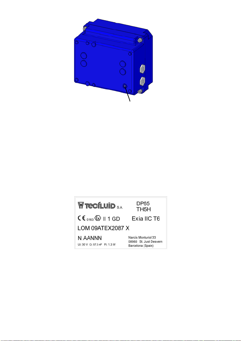
Earth connection
11.3 Technical characteristics of the Exi version
Maximum voltage: 30 VDC
Maximum load in the 4-20 loop: 900 (at 30 VDC supply voltage)
Ambient temperature: -5 - +40 ºC
Pulse output: Not available in this version.
The rest of characteristics are the same as in the point 10.
11.4 Marking
A drawing of the marking . For example, for a DP65.
The marking of the equipment shows the following characteristics:
- Manufacturer
- Model
- Serial number (year of construction and number)
- CE marking
- ATEX marking
- Certification number
- Address of the manufacturer
10
Page 11

11.5 Exi parameters
Marking Ex ia IIC T4 Ex ia IIC T6
Specific parameters
12 TROUBLESHOOTING
Problem Probable cause Remedy
The analog output gives
always 0 mA
The pointer rubs on the
scale
When the float is moved
the pointer follow it, but
does not return to 0
The pointer is displaced
with respect to the zero
of the scale.
Cables disconnected.
Normally occurs from a blow or fall
of the instrument.
The pointer is not properly secured
to the shaft.
Blow or fall of the instrument.
Ui : 30 V
Ii : 165 mA
Pi : 1,3 W
Ci : 57,3 nF
Ui : 30 V
Ii : 165 mA
Pi : 1,3 W
Ci : 57,3 nF
Check the cable connection.
Straighten the pointer by bending
it gently until separate it 2-3 mm
from the scale surface.
Set the pointer on the conical
shaft through a soft and careful
blow.
Match the pointer to the 0 of the
scale by means of the adjustment
screw of the pointer, turning left or
right according to convenience.
Hold the shaft in such a way that
is not bent or damaged.
Note: To remove the cover, it is necessary to remove the four screws "allen" M5 + plastic
washers in the back of the housing.
In all cases, check that there is no friction between the movement of the needle and the
connecting cables of the limit switches or transmitters.
When the pointer of the instrument is handled, it can become in a loss of accuracy of the
transmitter.
11
Page 12

WARRANTY
Tecfluid S.A. GUARANTEES ALL ITS PRODUCTS FOR A PERIOD OF 24 MONTHS, after
consignment, against all defects in materials and workmanship.
This warranty does not cover failures which can be imputed to misuse, use in an application different
to that specified in the order, the result of service or modification by un-authorized persons, bad
handling or accident.
This warranty is limited to cover the repair or replacement defective parts which have not been
damaged by misuse.
This warranty is limited to the repair of the equipment and all further and eventually following
damages are not covered by this warranty.
Any consignment of equipment to our factory or distributor must be previously authorised. The
consignment should be done with the equipment well packed, clean of any liquids, grease or
hazardous materials.
Together with the equipment, a note should be enclosed indicating the failure observed, the name,
address and telephone number of the sender.
SHIPPING
In the event of damages during shipping, claim directly to the carrier over a period of less than 24
hours. Tecfluid is not responsible for any damage caused during the shipment of material.
TECFLUID, S.A.
Narcís Monturiol, 33
E-08960 Sant Just Desvern
Tel. + 34 93 3724511 - Fax + 34 93 4734449
E-mail: [email protected]
Internet: www.tecfluid.com
The technical data in this document is subject to modification without notification, if the technical innovations in the product or
manufacturing processes so require.
 Loading...