

Page 1
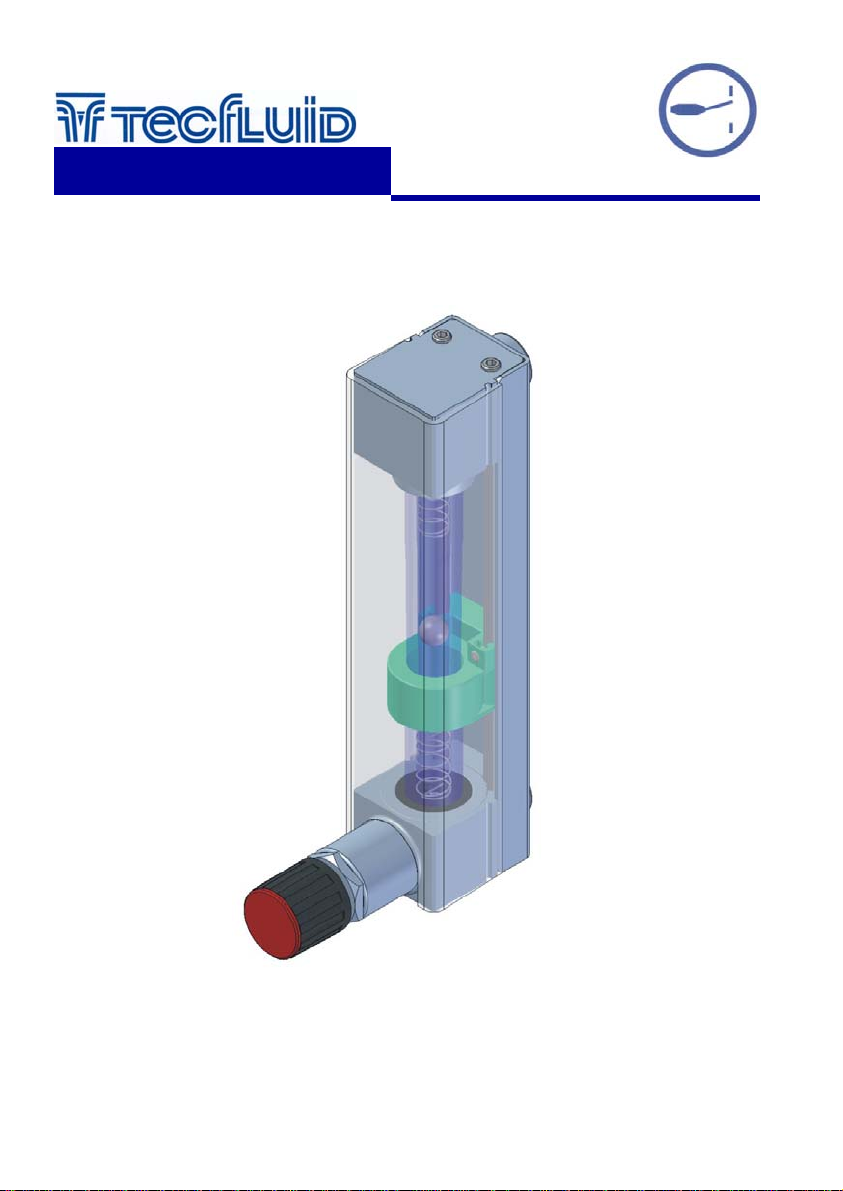
AMD Limit Switch
instrumentation
for fluids
For 2000 Series
Instructions Manual
R-MI-20AMD Rev.:0 English Version
Page 2
OPERATION
Flow rate variations displace the float in the metering tube and as it passes through the 20 AMD...
limit switch, the output changes from one state to the other.
The state is maintained until the float passes in the opposite direction at the limit switch position,
and the output changes to its original state.
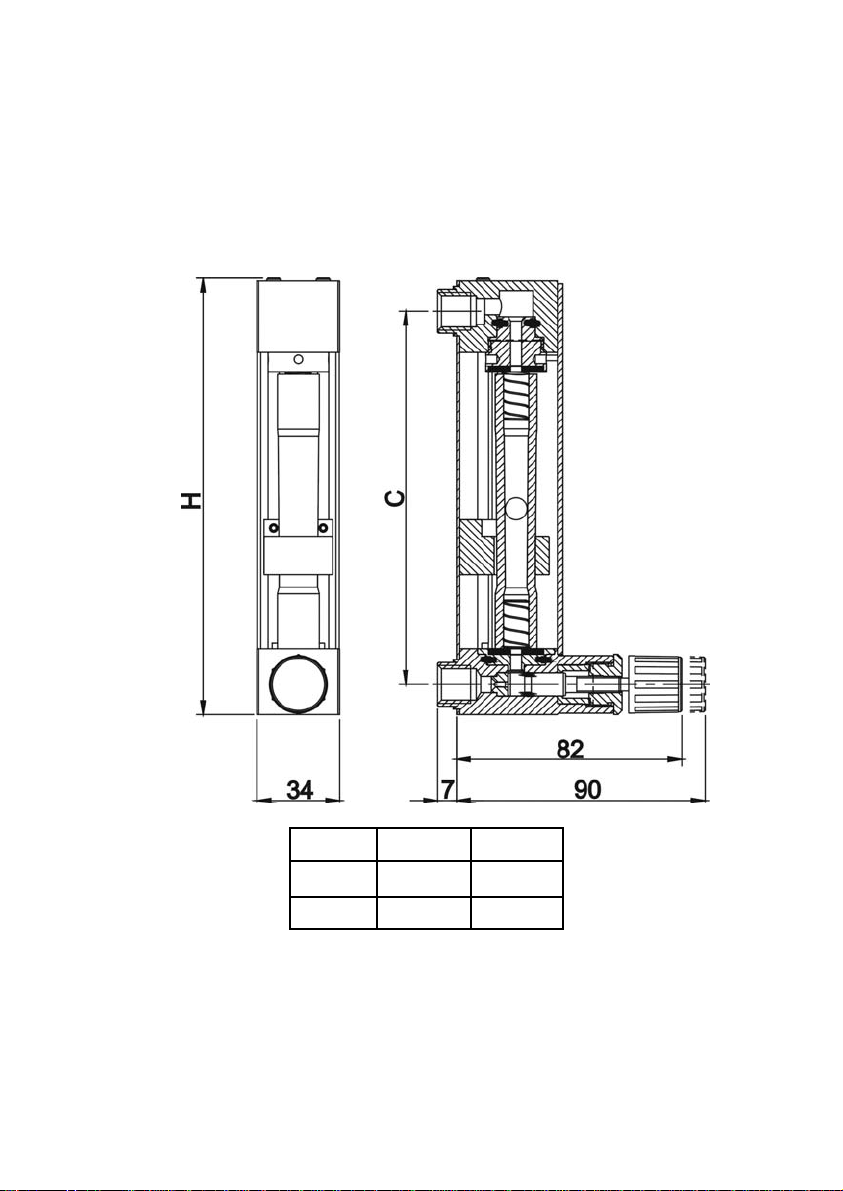
DIMENSIONS
MODEL C H
2100 136 mm 159 mm
2150 186 mm 209 mm
ELECTRICAL CONNECTION
The limit switch has a cable with two wires. For the electrical installation it is recommended to use a
cable similar to the cable of limit switch. The connection can be made by means of soldering or
with a terminal block, always making sure that the connection is protected against the ambient
(humidity, dust etc.)
2
Page 3
MAINTENANCE. Electrical verification of the limit switch
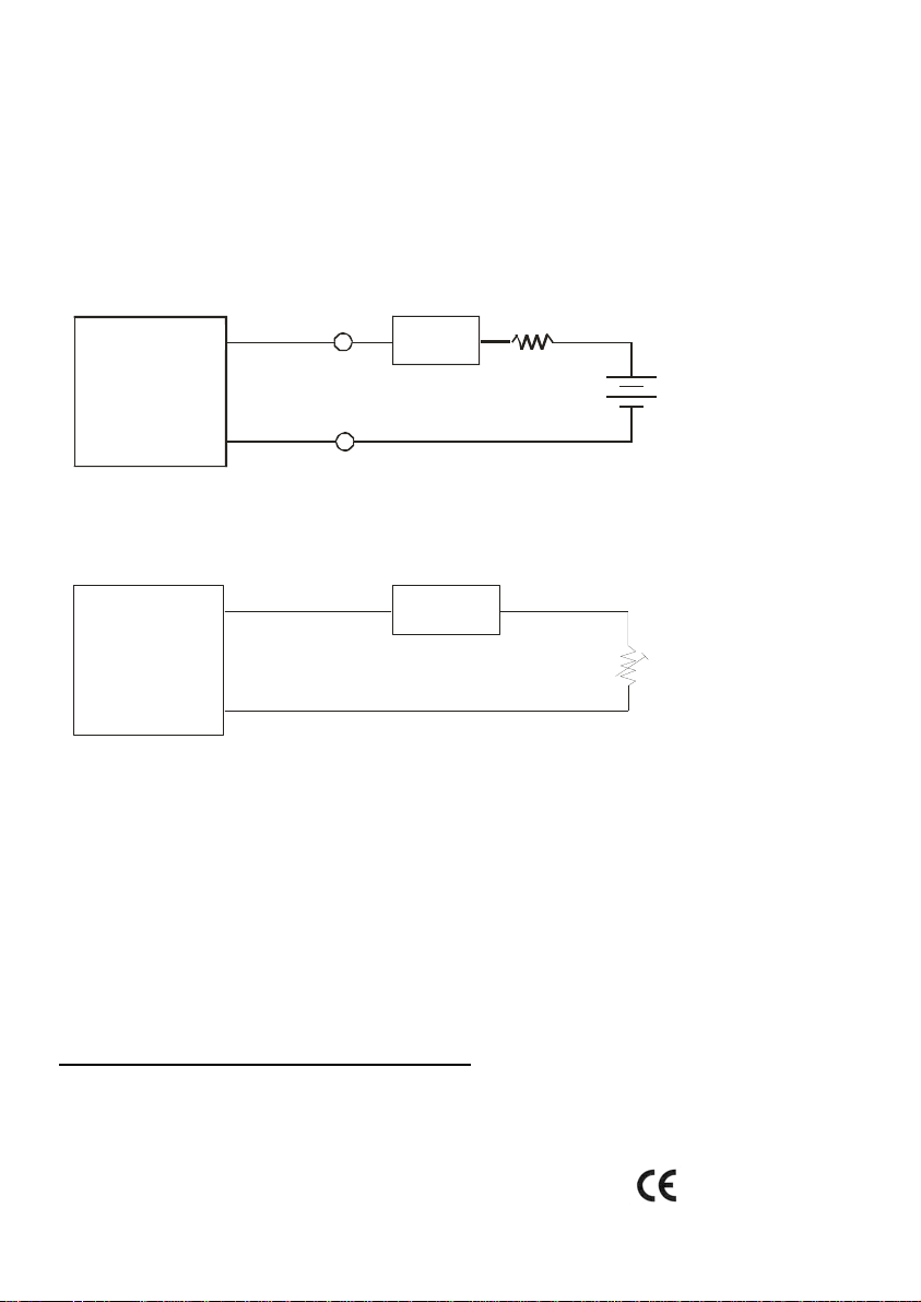
Connect a multimeter with the scale in DC mA, in series with the brown cable.
Verify that the current is more than 2.1 mA when the float goes trough the ring upwards, and less
than 1 mA when the float goes trough the ring downwards.
If you don’t have the NAMUR amplifier, the current can be checked using the following circuit
diagram:
Browrn
+
AMD
Blue
-
Multimeter
mA
-
If you don’t have the detector, the operation of the amplifier can be checked using the following
circuit diagram:
Amplifier
Multimeter
+
NAMUR
conection
+
mA
+
1 k
+
Battery 9 V
(Nominal 8 V for
NAMUR )
-
-
Potentiometer 20 k
-
With the potentiometer we modify the current of the NAMUR amplifier. The switching point must be
between 1.2 mA and 2.1 mA. That is, with the current below 1.2 mA the output relay must have a
state and above 2.1 mA the output relay must have the other state.
TECHNICAL CHARACTERISTICS
The AMD is a NAMUR (DIN 19234) sensor with the following nominal characteristics:
Nominal voltage 8 V
Power supply internal resistance 1 k
Current with the float below the AMD 1 mA
Current with the float above the AMD 2.1 mA
Power supply limits 5 ... 25 VDC
Ambient Temperature 0 ... +40 ºC
Self inductance ≤120 µH
Self capacity ≤90 nF
Conforms with the Directive EMC 89/336/EEC and ATEX 94/9/CE
3
Page 4

WARRANTY
Tecfluid S.A. GUARANTEES ALL ITS PRODUCTS FOR A PERIOD OF 24 MONTHS, after
consignment, against all defects in materials and workmanship.
This warranty does not cover failures which can be imputed to misuse, use in an application different
to that specified in the order, the result of service or modification by un-authorized persons, bad
handling or accident.
This warranty is limited to cover the repair or replacement defective parts which have not been
damaged by misuse.
This warranty is limited to the repair of the equipment and all further and eventually following
damages are not covered by this warranty.
Any consignment of equipment to our factory or distributor must be previously authorised. The
consignment should be done with the equipment well packed, clean of any liquids, grease or
hazardous materials. Tecfluid S.A. will not accept any responsibility for damage done during
transport.
Together with the equipment, a note should be enclosed indicating the failure observed, the name,
address and telephone number of the sender.
TECFLUID, S.A.
Narcís Monturiol, 33
E-08960 Sant Just Desvern
Tel. + 34 93 3724511 - Fax + 34 93 4734449
E-mail: [email protected]
Internet: www.tecfluid.com
The technical data in this document is subject to modification without notification, if the technical innovations in the product or
manufacturing processes so require.
 Loading...