

Page 1
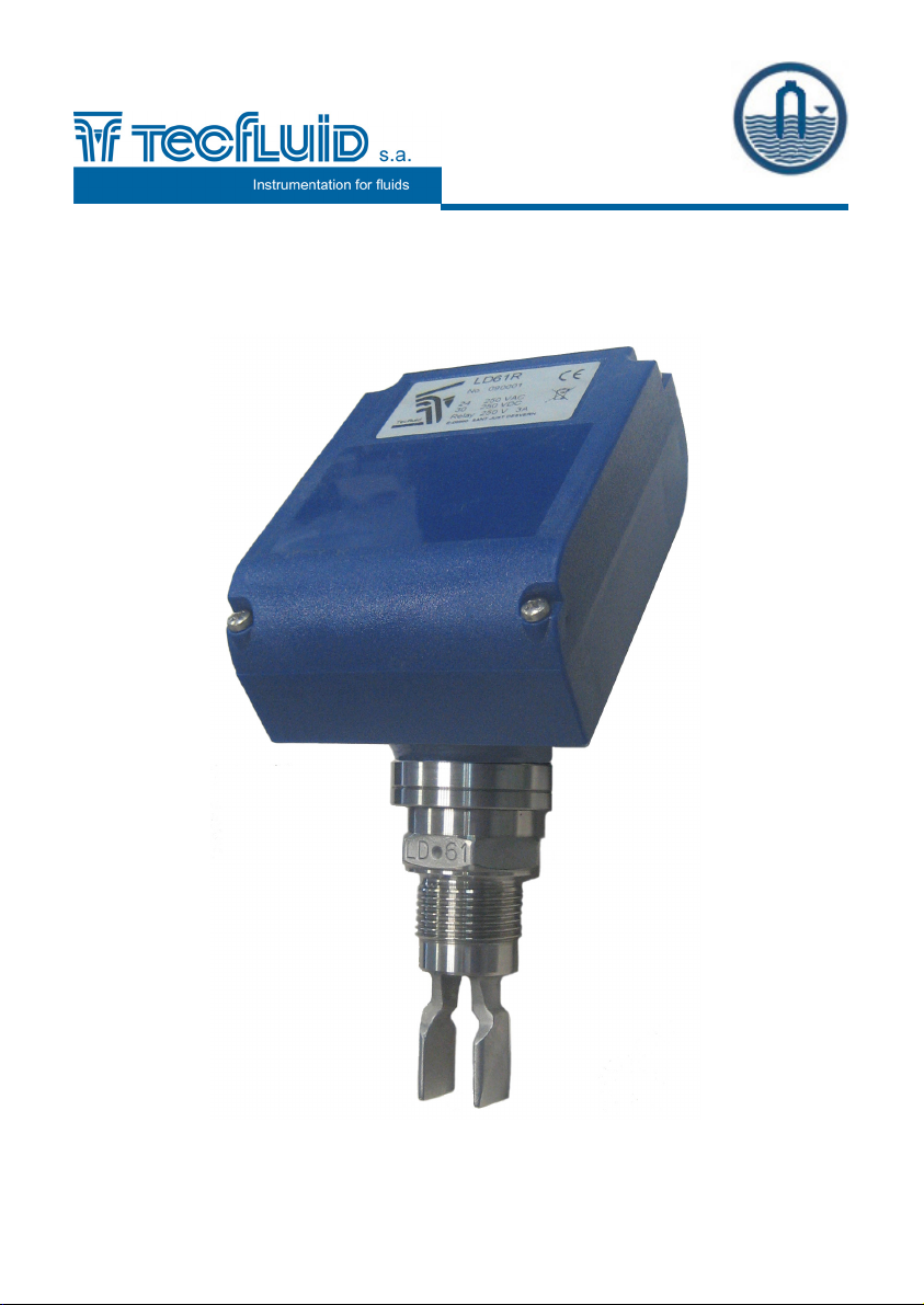
LD61R
Level switch
Instructions manual
R-MI-LD61R Rev.: 1 english version
1
Page 2

2 3
Page 3

TABLE OF CONTENTS
1. INTRODUCTION .................................................................................... 4
2. RECEPTION ........................................................................................... 4
3. INSTALLATION ...................................................................................... 4
4. ELECTRICAL CONNECTION ................................................................ 5
4.1. Power supply connection ......................................................... 6
4.2. Relay output connection ........................................................... 6
5. OPERATION ........................................................................................... 7
6. MAINTENANCE ...................................................................................... 7
6.1. Cleaning …………………………..……………………………........ 7
6.2. Fuse ……....…...…………………..……………………………........ 7
7. TECHNICAL CHARACTERISTICS ........................................................ 8
7.1. Materials ..................................................................................... 8
7.2 Process connection ........................................................................ 8
7.3 Power supply .............................................................................. 8
7.4 Relay characteristics ................................................................. 8
7.5 General characteristics ............................................................. 8
8. DIMENSIONS …………………................................................................ 9
9. TROUBLESHOOTING ……..................................................................... 11
Page 4
1. INTRODUCTION
The LD61R level switch is based on the variation of the natural resonant frequency of a
vibrating fork, when it is wetted by a liquid.
This variation is detected by the internal electronics and is used to determine the state of
the output .
2. RECEPTION
The LD61R level switches are supplied ready for installation and operation.
They are supplied packaged for their protection during storage and haulage.
To handle the detectors, they should always be held by the head, never by the vibrating
fork.
The vibrating fork should not be modified or bent, as this can damage the detector beyond
repair.
3. INSTALLATION
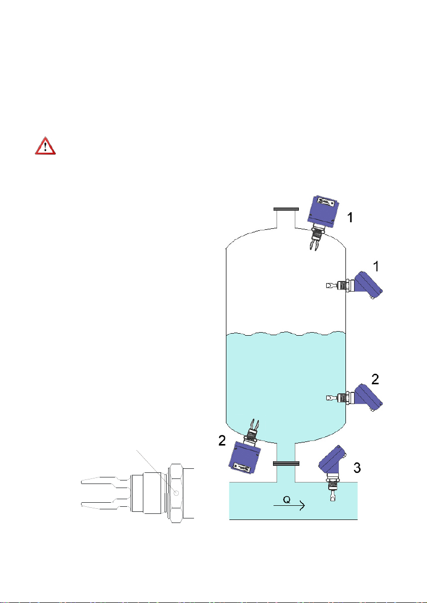
The LD61R level switch can be
mounted in any position. The more
usual insertion points are shown in the
figure 1.
In positions 1 the LD61R acts as a
maximum level switch. In positions 2
the LD61R acts as a minimum level
switch and in position 3 it acts as an
empty pipe detector (for example, to
protect a pump).
If the LD61R is installed in a horizontal
position it is recommended to install it
with the tines vertical to avoid
accumulation of substances, especially
in the case of high viscosity liquids.
To indicate the position of the tines the
LD-61 has a round mark on two of the
flats of the nut. These marks should be
in a vertical position when the detector
is installed in a horizontal position.
Punto de
Positioning mark
posicionamiento
Figure 1
4
Page 5
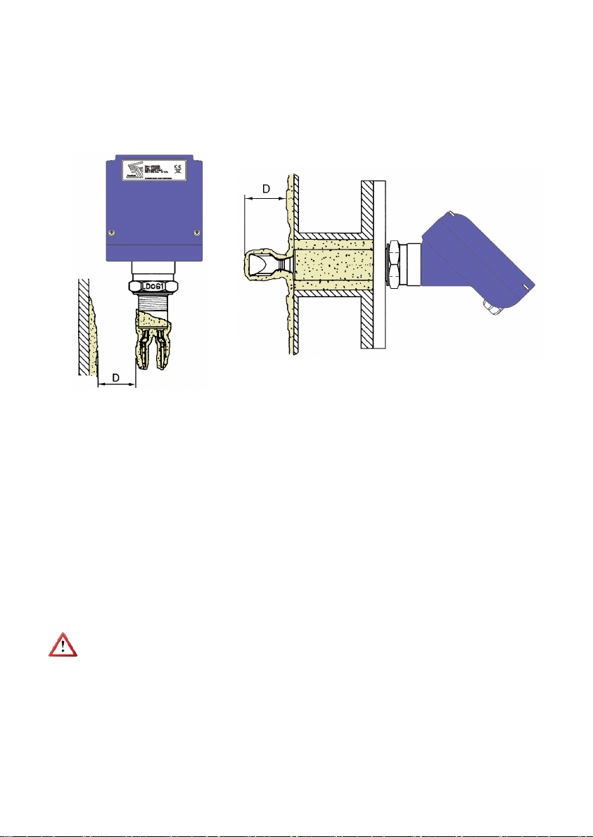
In the same way, when the switch is installed where there is flow, the position must be
taken into account. The flat part of the tines must be aligned parallel with the flow direction
as shown in figure 1.
If the viscosity is high, the tines must be kept away from other objects (such as the wall of
the tank). In these cases it is preferable to install a longer detector (figure 2).
It is recommended that the cables go downwards from the cable glands .
Figure 2
4. ELECTRICAL CONNECTION
For the electrical connection, the LD61R has a screw terminal strip.
For the electrical installation it is recommended to use multiple conductor cables with
individual cable sections in the order of 0.25 to 0.5 mm
connect. It is better to maintain the cables with mains voltage (power supply) separated
from the cables with low level signals.
Before starting the installation, check that the cable glands are the right size for the cables
to be used, this will guarantee the instrument will stay watertight. The PG11 cable glands
used are for cables with outside diameters between 6 mm and 10 mm.
Peel the outside insulation to free the inner cables. It is recommended to tin the ends of
the wires to avoid loose ends. Pass the cables through the cable glands and screw down
in the corresponding positions of the terminal strip. Once the wiring is finished make sure
that the cables are well gripped by the cable glands to maintain the degree of protection.
IMPORTANT NOTE: In order to comply with the electrical safety requirements as per EN61010-1 (IEC 1010-1), the installation of the equipment must take into account the
following:
A mains switch must be provided to disconnect the equipment. This switch must
be marked as the disconnecting device for the equipment and be within easy
reach of the operator.
The mains supply must have an earth line.
The housing must not be opened when the instrument has mains supply
connected.
2
in order to make it easier to
5
Page 6
Before installing the equipment, check that the supply voltage available in the installation
is compatible with the marked on the label of the instrument.
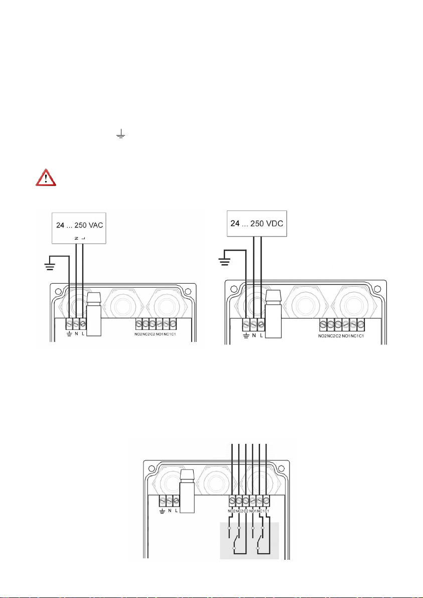
To help in the connecting of the equipment, the description of the terminals is marked on
the printed circuit next to the terminal strip.
4.1 Power supply connection
Terminal Power supply AC Power supply DC
Earth Earth
N Neutral (-)
L Live (+)
IMPORTANT NOTE: Power supply terminals are different from the ones in the previous
version. Be sure to connect properly the power supply as in the following image:
4.2 Relay output connection
Terminal
NO Normally open
NC Normally closed
C Common
6
Page 7

5. OPERATION
The LD61R can be installed as a detector of minimum or maximum level. To do that, it has
a switch inside the cover. Furthermore, the instrument has a LED that indicates the relay
ststus.
Change of
polarity switch
(maximum level)
Change of
polarity switch
(minimum level)
With the switch in the maximum level position, the common contacts of the relays are in
“normally open” when the detector is not in contact with the liquid (level below the
detector), and change to “normally closed” when the detector is submerged. The LED
changes from green to red.
With the switch in the minimum level position, the common contacts of the relays are in
“normally open” when the detector is in contact with the liquid (level above the detector),
and change to “normally closed” when the liquid falls below the detector. The LED
changes from green to red.
6. MAINTENANCE
The life of the vibrating fork depends basically on the abrasive characteristics of the
product used.
The LD-61 level switch only needs maintenance when the product, which can adhere to
the tines, will not let the detector change to a non detection state. In these cases the tines
must be cleaned.
6.1 Cleaning
To clean the tines, a brush suitable for removing the incrusted product, must be used .
You should not try to knock off the adhered product from the tines.
During the cleaning process, be careful not to apply force against the tines as this can
bend them and damage the detector beyond repair.
6.2 Fuse
In the event that the fuse blows, this should be replaced with a slow blow “T” fuse, size
Ø5 x 20 mm and 250 mA rating.
7
Page 8
7. TECHNICAL CHARACTERISTICS
7.1 Materials:
Fork: EN 1.4404 (AISI 316L). Others on demand.
Housing: Polycarbonate.
7.2 Process connection:
7.3 Power supply
24 ... 250 VAC / VDC
Power consumption: ≤ 1 W
7.4 Relay characteristics
Number of contacts and type: Double pole, double throw
Maximum switching current: 3 A
Maximum switching voltage: 220 VDC, 250 VAC
Maximum switching power: 60 W, 125 VA
Mechanical resistance: 15.0 x 10
7.5 General Characteristics
Viscosity: up to 10.000 cSt
Density: > 0,6 kg / l
Switching time: ≈ 1s
Hysteresis
: ± 2 mm with H2O
Process temperature (liquid): -30 ... 115ºC
Ambient temperature: -5 ... 40ºC
Standard pressure: PN25
Degree of Protection: IP67
Threads G1 (BSP), 1” NPT, DIN 11851, Clamp ISO 2852 fittings.
6
operations
Conforms with the 2006/95/CE Directive
Conforms with the 2002/96/CE Directive
Conforms with the 2004/108/CE Directive
Conforms with the 97/23/CE Directive
This equipment is considered as being a pressure accessory and NOT a safety
accessory as defined in the 97/23/CE directive, Article 1, paragraph 2.1.3.
8
Page 9
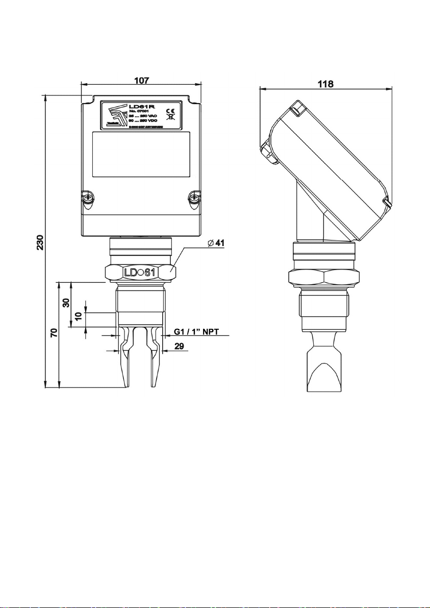
8 DIMENSIONS
G1 or 1” NPT thread
9
Page 10
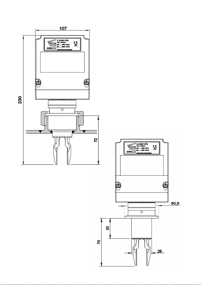
LD61TF/AISI316L SANITARY CONNECTION TF DIN405 Rd52 x 1/6
CLAMP-ISO2852 DN33,7/50,5 and 38/50,5
10
Page 11
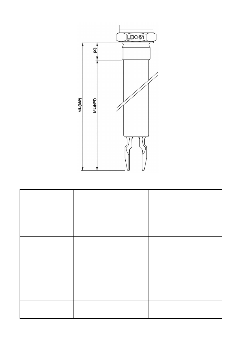
LD61R ML
9 TROUBLESHOOTING
Problem Probable cause Remedy
The instrument is
always detecting
product
The detector does not
vibrate and the LED
inside the cover is off
The detector vibrates
but does not change its
state
The detector changes
its state without
presence of fluid
Rest of product adhered on the
fork tines.
Power supply not correct.
Fused fuse. Change the fuse (250 mA T).
Damaged instrument. Contact with technical service
Interferences in the installation Contact with technical service
11
Clean softly the fork with a brush,
avoiding to press on the tines.
Verify that the power supply
cables are well connected to the
terminal strip and that the voltage
between them is correct.
Page 12

WARRANTY
Tecfluid S.A. guarantees all the products for a period of 24 months from their sale, against all faulty
materials, manufacturing or performance. This warranty does not cover failures which might be
imputed to misuse, use in an application different to that specified in the order, the result of service
or modification carried out by personnel not authorized by Tecfluid S.A., wrong handling or
accident.
This warranty is limited to cover the replacement or repair of the defective parts which have not
damaged due to misuse, being excluded all responsibility due to any other damage or the effects
of wear caused by the normal use of the devices.
Any consignment of devices for repair must observe a procedure which can be consulted in the
website www.tecfluid.com, “After-Sales” section.
All materials sent to our factory must be correctly packaged, clean and completely exempt of any
liquid, grease or toxic substances.
The devices sent for repair must enclose the corresponding form, which can be filled in via website
from the same “After-Sales” section.
Warranty for repaired or replaced components applies 6 months from repair or replacement date.
Anyway, the warranty period will last at least until the initial supply warranty period is over.
TRANSPORTATION
All consignments from the Buyer to the Seller´s installations for their credit, repair or replacement
must always be done at freight cost paid unless previous agreement.
The Seller will not accept any responsibility for possible damages caused on the devices during
transportation.
12
 Loading...