

Page 1
Electromagnetic
sensor
instrumentation
for fluids
Series
FLOMID FX
Instructions Manual
Conforms with the Pressure Equipment Directive 97/23/EC.
This equipment is considered as being a pressure accessory and NOT a safety accessory as defined in
!
the 97/23/EC directive, Article 1, paragraph 2.1.3.
R-MI-FlomidFX Rev.: 0
English version
0830
Page 2
WORKING PRINCIPLE
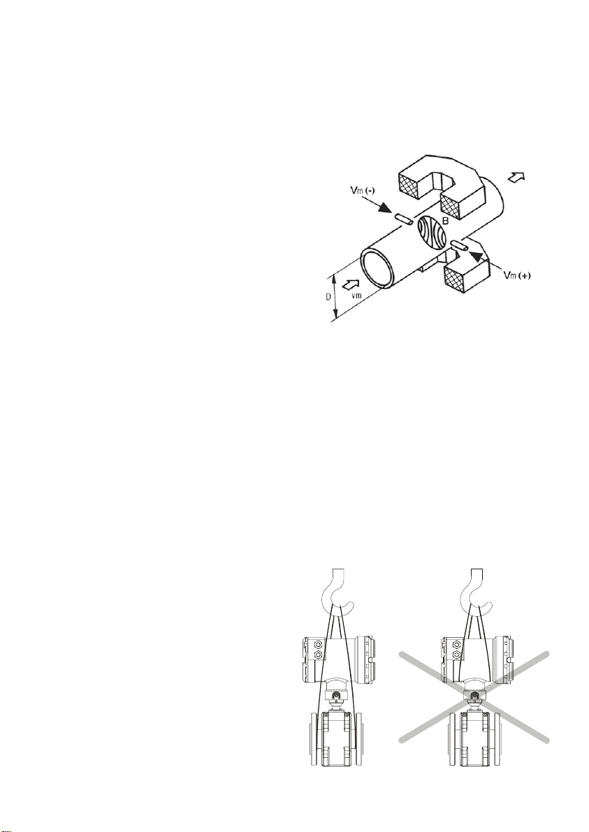
The Flomid electromagnetic flowmeters , are based on Faraday’s induction law.
When an electrically conductive liquid flows through a magnetic field, perpendicular to the flow
direction, it induces a voltage V
, proportional to the liquid velocity.
m
Two electrodes in contact with the liquid and positioned perpendicular to the magnetic field, sense
this voltage V
.
m
Vm = B·vm·D
Where:
V
= Measured voltage in the electrodes.
m
B = Magnetic flux density
v
= Average liquid velocity
m
D = Pipe diameter.
RECEPTION
The FLOMID electromagnetic flowmeters are supplied conveniently packed for transport together
with their instruction manual for installation and operation.
All the flowmeters have been verified in our calibration rigs to obtain the factor Fc for each sensor.
Disassembly
Unpack the instrument carefully, removing any remains of the packing from the inside of the
sensor. Do not remove the grease from the neck that couples to the electronics housing.
Storage temperature
Sensors linings of : PTFE and PVDF -20ºC ...... +60ºC
PP and EBONITE -5ºC ...... +50ºC
HANDLING
It should always be done with care and
without knocks.
The large diameter sensors have rings
for holding the elevation elements. If the
flowmeter is held using slings, these
should hold on the sensor and not on the
electronics housing (see the drawing).
2
Page 3

INSTALLATION
This should be made in a point that guarantees that the pipe is always completely full.
Avoid high points of the pipes where air pockets usually form, or pipes with falling flow where
vacuums can form.
Partially full pipes can produce important reading errors.
Flow rate measurement
with open discharge
makes it necessary to
install the flowmeter in a
pipe section with a siphon
which avoids stagnation of
air in the sensor.
Sensor position
The most adequate position is
with the electrodes in a
horizontal plane. In this way,
deposits of particles on the
electrodes are avoided.
Straight pipe sections
Are necessary before and after the
sensor. The minimum distances are
the following:
Upstream : 5 DN
Downstream : 3 DN
In installations with turbulent flow it
may be necessary to increase these
distances.
Mixtures
If liquids of different conductivities are mixed it is
necessary to install the sensor a minimum of 30 DN
from the point of mixture in order to obtain a uniform
conductivity of the liquid and stabilize the readings.
If this distance is less, the readings may be unstable.
3
Page 4
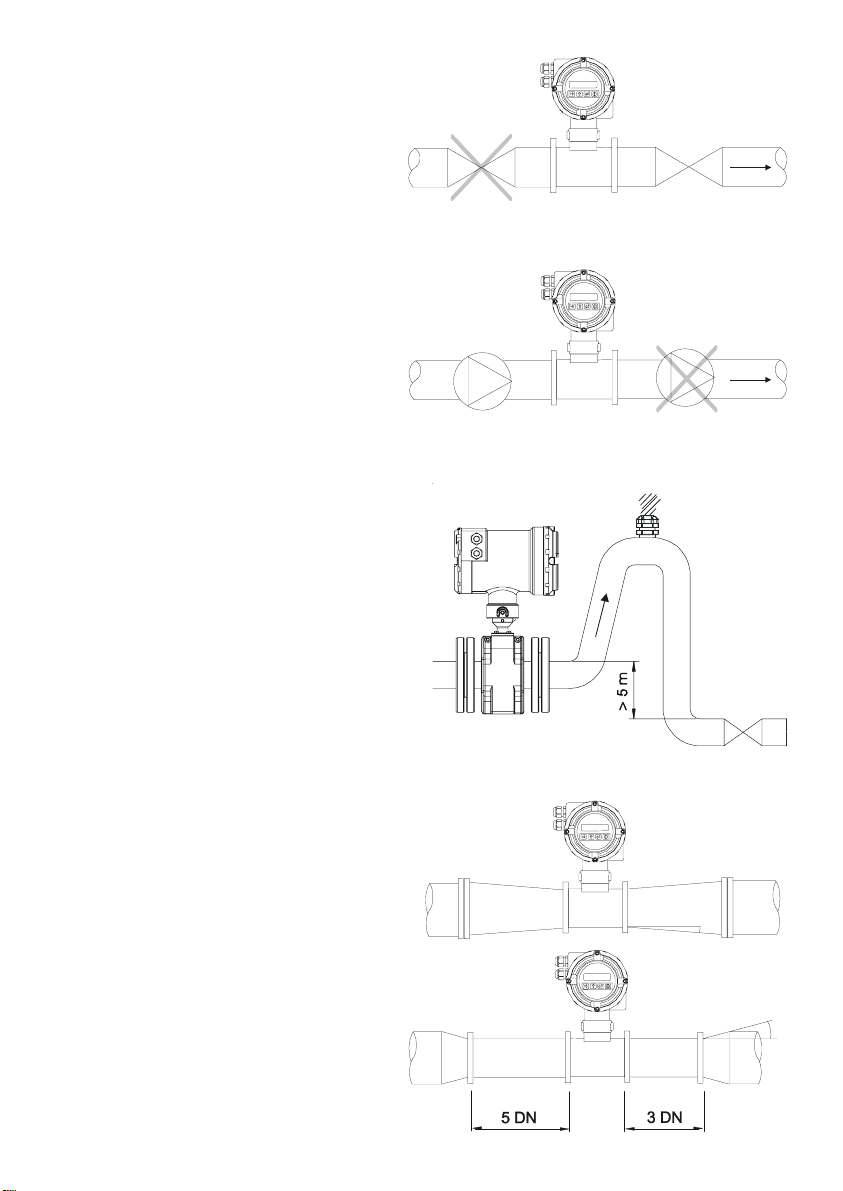
Control valves or stop cocks should
always be installed downstream from the
sensor to assure that the pipe is always
full of liquid.
Pumps should be mounted upstream from
the sensor to avoid the suction part of the
pump (vacuum) that could damage the
sensor liner (see the table on page 8).
If there is a point where the difference in level
is greater than 5 m an air inlet valve should
be installed after the sensor to avoid a
vacuum effect that could damage the sensor
liner (see the table on page 8).
Reduction of the DN
In installations where, for reasons of the
flow rate to be measured, a sensor of a
smaller DN than the pipe DN must be
mounted, the reduction must be done with
an angle smaller than 4º to avoid
turbulences that can give false readings.
If the reduction angle is greater then the
straight pipe sections indicated on the
previous page must be respected.
4
α <
α >
4º
α
4º
α
Page 5
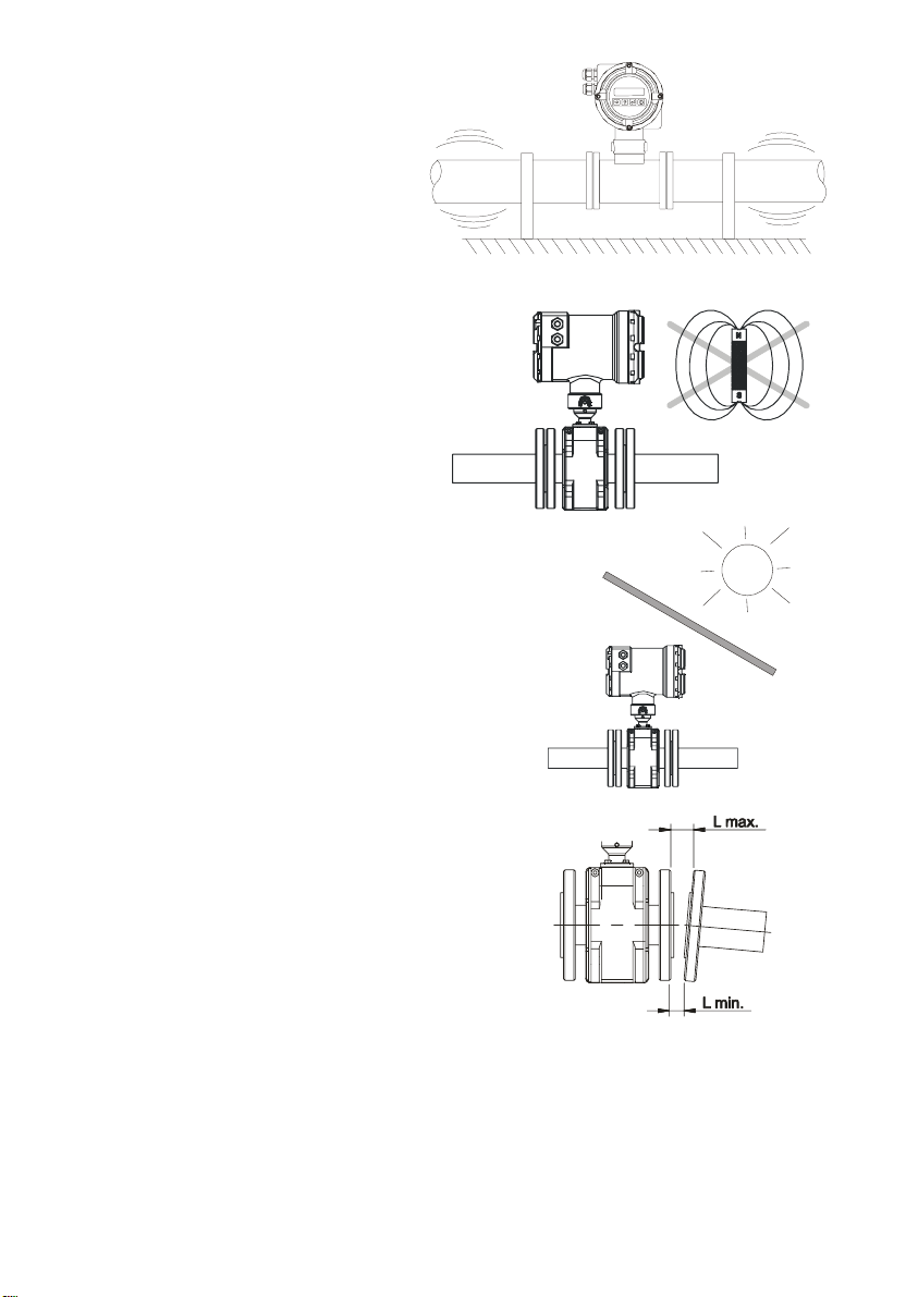
Vibrations
Vibrations of the pipes should be avoided
by anchoring the pipe before and after the
sensor.
The vibration level should be less than 2.2
g in the range of 20 -150 Hz according to
IEC 068-2-34.
Magnetic fields
Strong magnetic fields close to the sensor
should be avoided.
Temperature
In open air installations it is recommended to install a
protection to avoid direct sun light on the flowmeter.
With thermally insulated pipes DO NOT insulate the
sensor. High temperatures can damage it.
The maximum liquid temperatures are shown on
page 8.
MOUNTING
Parallelism
The maximum parallelism error must be less than 0.5 mm
(L
max—Lmin ≤ 0,5 mm).
Gasket position
For the sandwich mounting sensors, to avoid leakage into the inside of the sensor one must make
sure that the rubber gasket (A) (drawing on the following page) is fitted into the stainless steel ring
so that it will be pressed directly on the plastic liner. If the rubber gasket seals against the
stainless steel ring then the liquid pressure will force liquid into the interior of the sensor causing
irreparable damage.
5
Page 6
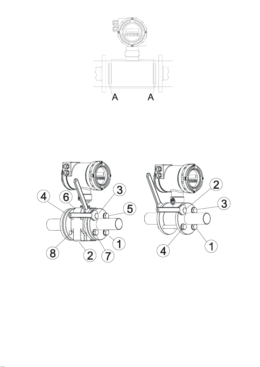
Tightening torque
The tightening torque for the flange bolts should not exceed 32 Nm for working pressures of 16
bar maximum.
This tightening torque should be applied to sandwich mounting (Flomid 0FX) and also to DIN,
ANSI, JIS etc. flange mounting sensors for the same working pressure of 16 bar.
The maximum tightening torque varies in function of the nominal pressure (PN) of the sensor.
The tightening of the bolts should be uniform, following the sequence shown in the drawings and
depending on the number of flange bolts.
SENSOR EARTH CONNECTION (only for sandwich and flange mounting sensors )
To obtain correct operation the sensor should have its functional earth connected to a point that is
in direct contact with the liquid to be metered.
The earth cables should assure a good electrical contact. To obtain this, they should be well
screwed down and with a good contact on both sides of the sensor. It is important to eliminate
paint or coverings that act as insulation of the connection.
The functional earth connection should be used exclusively for the sensor given that parasitic
signals caused by other electrical equipment connected to this earth can cause malfunction of the
sensor.
In the case that there are high voltage differences between different earth points, this will cause
currents that may give problems in the readings (empty pipe indication). In these cases, do not
connect the functional earth to the protective earth of the mains.
6
Page 7
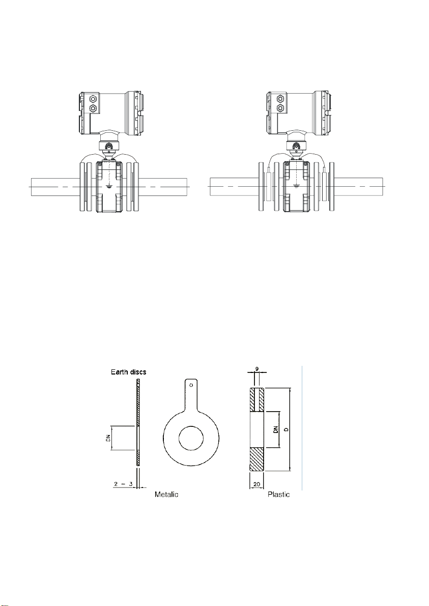
The connection of the functional earth should be made as follows:
A) In the case of metallic pipes without internal lining connect the earth cables to the
counterflanges.
B) In the case of metallic pipes with internal lining or plastic pipes, connect the earth cables to
the earth disks, supplied on demand.
METALLIC PIPES METALLIC PIPES
Without internal lining With internal lining
or PLASTIC PIPES
EARTH DISKS
The earth disks are necessary when the installation is with plastic pipes or metallic pipes with an
internal insulating lining (PTFE, PVDF, PP EBONITE etc.).
The earth disks are supplied in two versions:
METALLIC, in the form of a disk in stainless steel EN 1.4404 (AISI316L), for liquids compatible
with this material.
PLASTIC, that have an electrode to make the contact with the liquid. The materials (plastic and
metal) depend on the product to be metered.
The electrodes can be EN 1.4404, Hastelloy C, Titanium, Zirconium, etc..
MAINTENANCE
It is recommended to clean the electrodes in installations where incrustations or appreciable
sedimentations can occur.
Cleaning can be done using liquid detergents and medium hard brushes.
7
Page 8
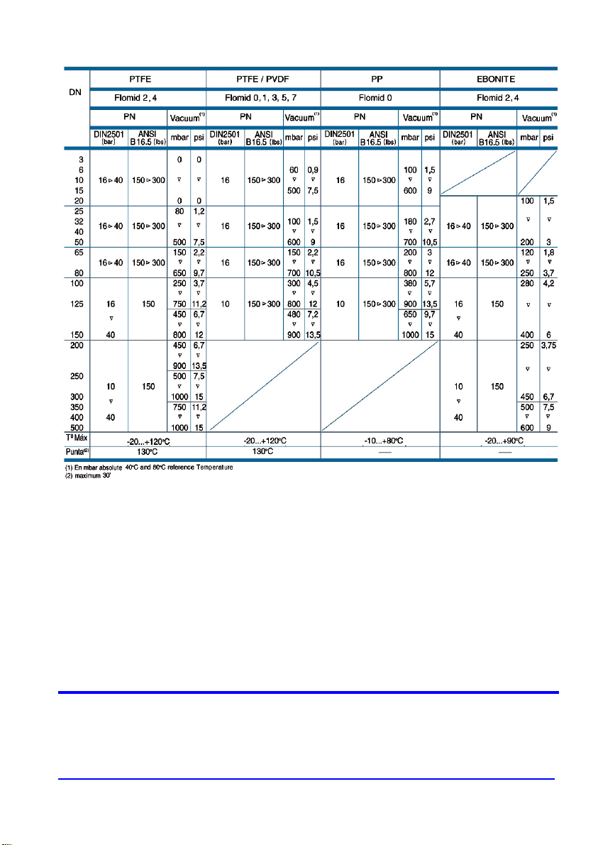
TEMPERATURE, PRESSURE and VACUUM LIMITS
WARR ANTY
Tecfluid S.A. GUARANTEES ALL ITS PRODUCTS FOR A PERIOD OF 24 MONTHS, after consignment, against all
defects in materials and workmanship.
This warranty does not cover failures which can be imputed to misuse, use in an application different to that specified
in the order, the result of service or modification by un-authorized persons, bad handling or accident.
This warranty is limited to cover the repair or replacement defective parts which have not been damaged by misuse.
This warranty is limited to the repair of the equipment and all further and eventually following damages are not
covered by this warranty.
Any consignment of equipment to our factory or distributor must be previously authorised. The consignment should
be done with the equipment well packed, clean of any liquids, grease or hazardous materials. Tecfluid S.A. will not
accept any responsibility for damage done during transport.
Together with the equipment, a note should be enclosed indicating the failure observed, the name, address and
telephone number of the sender.
TECFLUID, S.A.
Narcís Monturiol, 33
E-08960 Sant Just Desvern
Tel. + 34 93 3724511 - Fax + 34 93 4734449
E-mail: [email protected]
Internet: www.tecfluid.com
The technical data in this document is subject to modification without notification, if the technical innovations in the product or
manufacturing processes so require.
 Loading...