

Page 1
Flow switches
Series
AD 15 / ADI 15 / ADT 15
Mounting instructions
AD-15
Working principle
Series AD-15, ADI-15, ADT-15
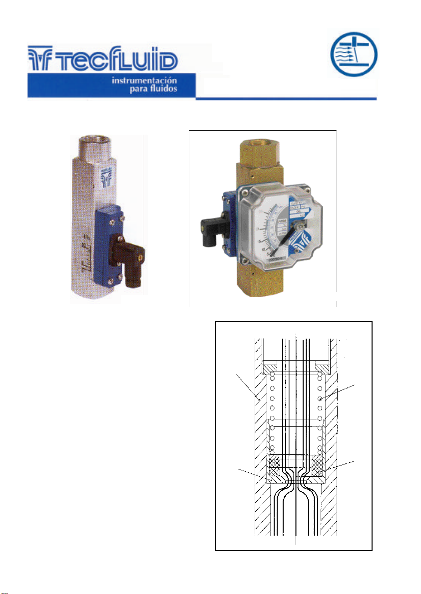
If a fluid flows with enough flow rate through a metering
pipe A, with a mobile disc B and a calibrated spring C,
the disc will be displaced.
The distance depends on:
− The flow rate F.
− The relation between the areas A and B.
− The opposing force of the calibrated spring C.
− The equilibrium of the forces defines the position of
the calibrated disc B, and at the same time, the flow
rate.
The calibrated disc B has a magnet M. The magnetic
field acts on the alarms, the indicator or the transmitter.
A = Metering tube
B = Calibrated metering disc
C = Calibrated spring
F = Flow rate
M = Magnet
C-MI-AD15 Rev.:1
A
B
English version
ADI / ADT-15
C
M
F
Page 2
Technical data
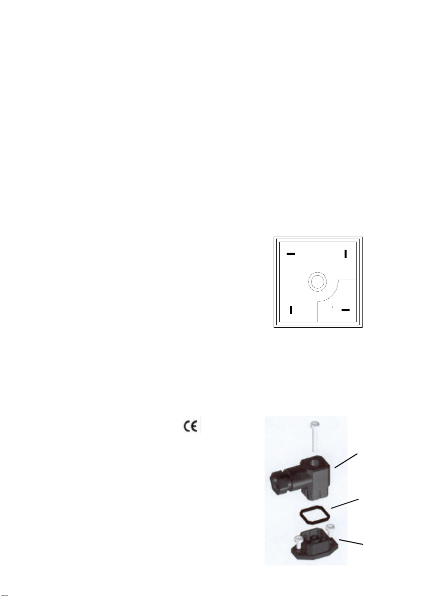
Once the electrical connection has been made
and the cable gland is tight, assemble in the
position the female connector (A) on the
male base (C). Don’t forget to put the rubber
1
2
Series AD-15, ADI-15, ADT-15
• Accuracy: ± 5% of full scale.
• Measuring range: 10:1,6
• Disc displacement: 40mm ± 5mm.
• Scales: In l/h, l/min, l/seg, m³/h,
%, etc.
• Mounting positions:
Vertical or horizontal. Flow rate in
any direction.
• Connections: From ¼” BSP to 2 ½” BSP.
Others on demand.
• Materials: Brass from 1/4” to 1”.
Aluminium from 1 1/4” to 2 1/2”.
(AISI-316, PTFE on demand)
• Maximum pressure: 16 bar.
• Maximum temperature:
100ºC continuous, 120ºC maximum.
• Alarms: - ¼” and ½” connections:
ADR-01: Reed 0,25A 125V 3VA
- ¾” to 2 ½” connections:
ADR-11: Reed 0,5A 250V 60VA
Polyamide housing with IP65
connector.
/1A = 1 alarm.
/2A = 2 alarms.
• Indicator: Needle on a graduated scale. Flow
rate units. Aluminium housing with
plastic window.
• Transmitter: 4-20 mA. 2-wires, linear scale,
series Halltec II.
HALL sensor without contact with
the metering system.
• Power supply: 15 to 50 Vdc.
• Temperature: -5 to +70ºC.
• Precision: Analog output respect the magnet
position: < 0.6%
• Maximum load in the 4-20 mA loop:
(Vs—10)/0.02 O
(Vs is the supply voltage).
• Consumption: Maximum 20 mA.
• Complies with 73 / 23 / CEE directive
Adjusting the set point
The switch housing has a line on the side next
to the graduated scale.
The position of this line indicates the value at
which the switch will act.
The switch is held in position by means of a
screw in a guide.
To adjust the position of the switch, loosen the
fixing screw and slide the switch to the desired
position.
Connection
In the female connector (A):
Terminal 1: Reed common.
Terminal 2: Normally closed.
Terminal 3: Normally open.
Earth terminal: No connection.
( Reed on zero position ).
3
Installation
correct
seal (B) between the connectors.
A
B
C
Page 3
Install the flow rate detector in a pipe, with the arrow in the fluid direction.
For the electrical installation, a multi-conductor cable should be used to obtain a good seal
with the cable gland. The connector is provided with a PG 9 cable gland, suitable for a 4.5 to 7 mm outside diameter cable. Connect the reed switch as required. Terminal 3 of the connector is the common,
terminal 2 is the normally closed (N.C.) contact and terminal 1 is the normally open (N.O.) contact when
there is no flow. The fourth terminal is an earth connection which is connected to the body of the flow
rate detector.
The electrical installation should provide a fuse or circuit breaker to protect the reed switch
from overloads.
Make sure that the contact rating is not exceeded. If high loads are to be switched, use an
auxiliary relay.
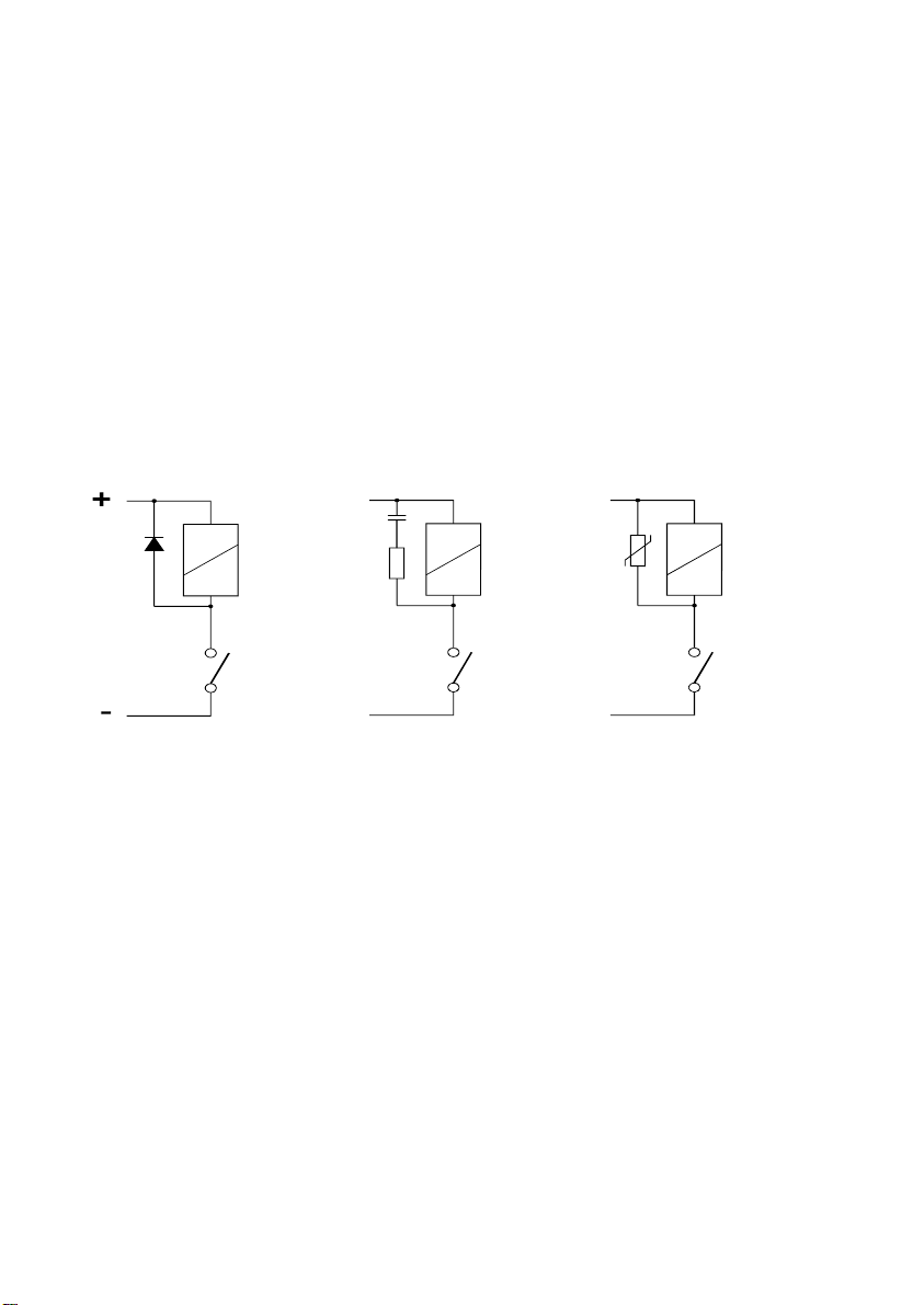
When using inductive loads, such as relays or electro-valve coils, surge arresters should be
installed to protect the reed contacts.
With a dc supply, a diode should be connected as shown.
C
VDR
Coil
Coil
R
Coil
DC Supply
Reed
AC Supply
Reed
Reed
AC Supply
For an ac supply, an RC circuit can be used as shown, although a varistor (VDR) is better
and is easier to select the right value. The VDR should have a breakdown voltage greater than 1.5
times the rms voltage. The standard varistor ratings specify the rms working voltage for the varistor, for
example a S05K25 varistor will be for 25 V
working and will have a breakdown voltage of 39 V at 1
rms
mA.
Page 4
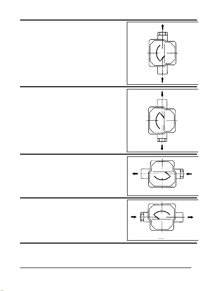
Mounting
Rising
Series AD-15/BD
ADI-15/BD
ADT-15/BD
Falling
Series AD-15/DAB
ADI-15/DAB
ADT-15/DAB
BD
DAB
Right to Left
Series AD-15/DES
ADI-15/DES
ADT-15/DES
DES
Left to Right
Series AD-15/ED
ADI-15/ED
ADT-15/ED
ED
TECFLUID, S.A.
Narcís Monturiol, 33
E - 08960 Sant Just Desvern
Tel. + 34 93 3724511 - Fax + 34 93 4730854
The technical data in this pamphlet is subject to modification without notification, if the technical innovations in the product or
manufacturing processes so require.
 Loading...