

Page 1
AMO
Flow Detector
instrumentation
for fluids
For Series 2000 and 6000
Instructions Manual
E-MI-AMO Rev.: 1 English Version
Page 2
1. OPERATION
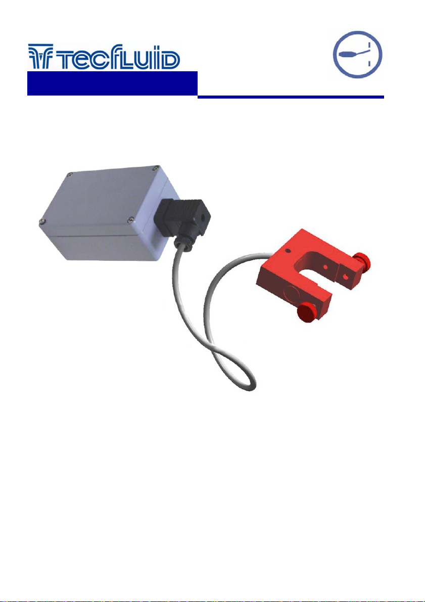
The AMO is an optical flow rate detector. It is used with variable area flowmeters that employ
transparent flow metering tubes and transparent liq uids. The AMO d etects the prese nce of the float
and its direction of displacement , s o it ca n act as a ma xim um or mini mum fl o w s witch. The de tector
state is maintained until the float passes in the opposite direction at the limit switch position,
switching to its previous state.
2. INSTALLATION INSTRUCTIONS
2.1 Installing the detector
A range of different detectors are available to adap t to the different types and sizes of metering
tubes. The physical form of the detectors may vary, but their operation is identical.
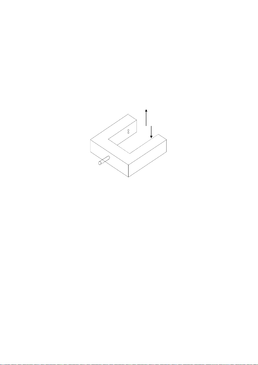
The detectors are fixed to the flowme ter chassis by means of screw s located a t the ends of the
arms.
Activate
Deactivate
2.2 Type of alarm
The detectors have two sensing elements mounted in one of the arms and an infrared emitter
mounted in the opposite arm. When the detector is mounted as shown above with the two
sensing elements to the (Pos.1), the relay of the flow switch is activated when the float rises and
is deactivated when the float falls. In this position the AMO ca n be used as a maximu m alarm
and is deactivated in absence of the power supply, or it can be used as a minimum alarm that is
activated in absence of the power supply. If the detector position is changed placing the sensing
elements at the right (Pos.2), the systems logic in inverted.
Float Position Pos.1 Pos.2 Relay
Flow rate < Set Point X Deactivated
Flow rate < Set Point X Activated
Flow rate > Set Point X Activated
Flow rate > Set Point X Deactivated
The following precautions must be taken when using an AMO:
- Sunlight and light from incandescent bulbs can affect the operation of the system. The
detector must be mounted in a position where direct light does not fall on the sensing
elements.
- Transparent or red translucent floats are not recommend ed since the infrared light can go
through them and the sensor elements may not be activated.
- The liquids should be transparent and clean.
2
Page 3
2.3 Installation of the control unit
For the electrical installation the use of multipl e cables with individ ual cable sections in the o rder
2
of 1 mm
is recommended.
IMPORTANT: In order to comply with the electrical safety requirements as per EN-61010-1 (IEC
!
1010-1), the installation of the equipment must take into account the following:
• A mains switch must be provided to disconnect the equipment. This switch must be
marked as the disconnecting device for the equipment and be within easy reach of the
operator.
• The mains supply must have an earth line when the power supply is above 48 Vac.
• The housing must not be opened when the instrument has mains supply connected.
Before starting to install the equipment, check that the supply voltage available is the same as
marked on the label of the instrument situated inside the top cover.
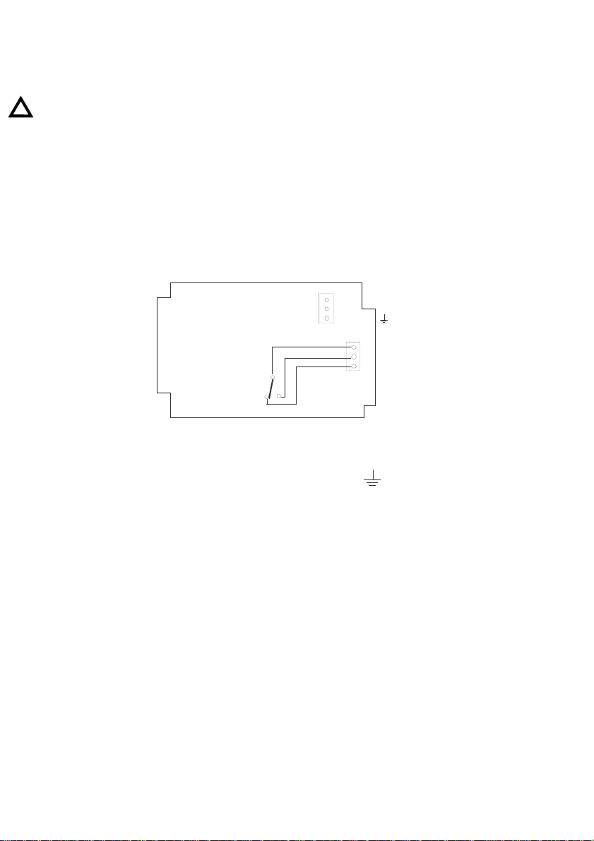
The connections are made by means of a screw terminal strip.
L
RED
N
MAINS
C
NO
RELÉ
NC
2.3.1 Power Supply Connection
The po we r suppl y is c on nec te d to the te rmin als mar ked "N " & "L ". Th e ea rt h line s houl d be
connected to the terminal marked with the earth symbol
2.3.2 Relay connection
“C” is the common contact, "NO" is the normally open contact and “ NC” is the normally
closed contact.
3. SET UP INSTRUCTIONS
3.1 Set Point
The set point is obtained by moving up or down the position of the detector to the height of the
required flow rate.
4. CHARACTERISTICS
4.1 Power Supply
Power Supply Voltage:
Standard : 220 VAC 50/60 Hz
On Order : 240 VAC, 110 VAC, 24 VAC 50/ 60 Hz
Power Consumption : Less than 2 VA
Fuse : 250 mA Slow blow (T) 5 x 20 mm
3
Page 4

4.2 Relay
Characteristics of the relay contacts:
Maximum switching voltage : 250 VAC
Maximum current capacity : 3 A
Maximum switching power : 500 VA
4.3 General Characteristics
Ingress protection : IP65
Maximum Temperature : 60 ºC
Conforms to the Directive 89/336/EEC
Conforms to the Directive 73/23/EEC
WARRANTY
Tecfluid S.A. GUARANTEES ALL ITS PRODUCTS FOR A PERIOD OF 24 MONTHS, after
consignment, against all defects in materials and workmanship.
This warranty does not cover failures which can be impu te d to misuse, use in an appli catio n dif fe ren t
to that specified in the or der, the result of service or modification b y un-authorized persons, bad
handling or accident.
This warranty is limited to cover the repair or replacement defective parts which have not been
damaged by misuse.
This warranty is limited to the repair of the equipment and all further and eventually following
damages are not covered by this warranty.
Any consignment of equipment to our factory or distributor must be previously authorised. The
consignment should be done with the equipment well packed, clean of any liquids, grease or
hazardous materials. Tecfluid S.A. will not accept any responsibility for damage done during
transport.
Together with the equipment, a note should be enclosed indicating the failure obs erved, the name,
address and telephone number of the sender.
TECFLUID, S.A.
Narcís Monturiol, 33
E-08960 Sant Just Desvern
Tel. + 34 933 724 511 - Fax + 34 934 734 449
E-mail: [email protected]
Internet: www.tecfluid.com
The technical data in this document is subject to modification without notification.
 Loading...