

Page 1
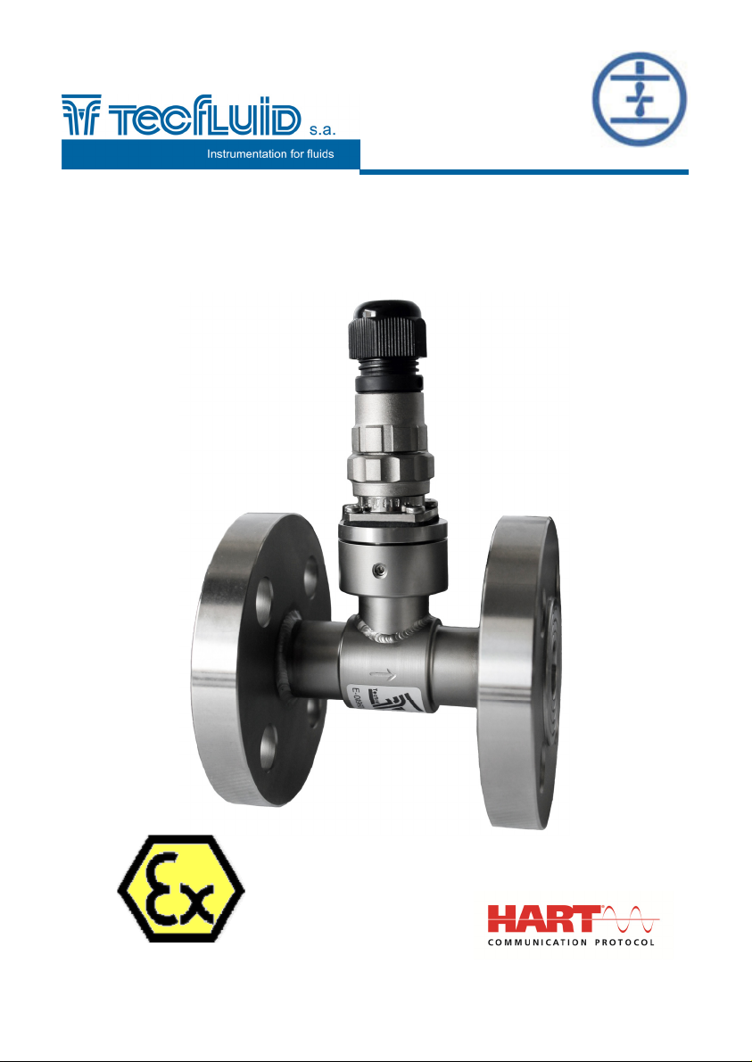
Turbine
flowmeter
Series TM
Instructions manual
R-MI-TM Rev.: 2 English version
Page 2

PREFACE
Thank you for choosing the flowmeter series TM from Tecfluid S.A.
This instruction manual allows the installation and operation of the
turbine flowmeter series TM. It is recommended to read it before
using the equipment.
WARNINGS
This document shall not be copied or disclosed in whole or in
any part by any means, without the written permission of
Tecfluid S.A.
Tecfluid S.A. reserves the right to make changes as deemed
necessary at any time and without notice, in order to improve
the quality and safety, with no obligation to update this manual.
Make sure this manual goes to the end user.
Keep this manual in a place where you can find it when you
need it.
In case of loss, ask for a new manual or download it directly
from our website www.tecfluid.com Downloads section.
Any deviation from the procedures described in this instruction
manual, may cause user safety risks, damage of the unit or
cause errors in the equipment performance.
Do not modify the equipment without permission. Tecfluid S.A.
is not responsible for any problems caused by a change not
allowed. If you need to modify the equipment for any reason,
please contact us in advance.
2
Page 3

TABLE OF CONTENTS
1 WORKING PRINCIPLE ......................................................................... 4
2 RECEPTION ........................................................................................... 4
2.1 Unpacking ................................................................................. 4
2.2 Storage temperature ................................................................ 4
3 INSTALLATION ..................................................................................... 4
3.1 Filter ........................................................................................... 5
3.2 Open discharge ........................................................................ 5
3.3 Position ..................................................................................... 5
3.4 Straight pipe sections .............................................................. 5
3.5 Valves ........................................................................................ 6
3.6 Pumps ......................................................................................... 6
3.7 Electrical connection ............................................................... 7
4 MAINTENANCE .................................................................................... 8
4.1 Disassembly .............................................................................. 9
4.2 Cleaning .................................................................................... 9
4.3 Mounting ................................................................................... 9
4.4 Pickup ........................................................................................ 9
4.5 Replacing the pickup ............................................................... 9
5 PART LIST ............................................................................................ 10
6 TECHNICAL DATA ................................................................................ 11
7 DIMENSIONS AND WEIGHTS ............................................................... 12
8 K FACTOR (PULSES / LITRE) .............................................................. 14
9 ADDITIONAL INSTRUCTIONS FOR THE ATEX VERSION ................. 14
9.1 Intrinsic safety .......................................................................... 14
9.2 Flameproof enclosure .............................................................. 14
9.2.1 Facilities connecting conductive parts to earth ...................... 15
9.2.2 Maintenance .............................................................................. 15
9.2.3 Technical data for the ATEX version ...................................... 15
9.2.4 Marking ...................................................................................... 16
9.2.5 Dimensions and weights ......................................................... 17
10 TROUBLESHOOTING ........................................................................... 19
3
Page 4
1
WORKING PRINCIPLE
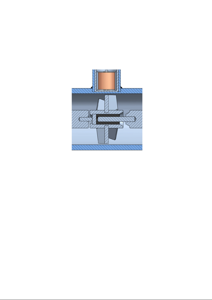
helical rotor turns freely inside a cylindrical tube.
One
The working liquid pushes the rotor blades, making them turn at a flow speed which is
proportional to the flow rate.
A pick-up coil mounted externally receives the propeller turns and generates an electrical
signal which, once treated by the different electronic converters, can provide flow rate
indication, total or partial volume, digital and analog outputs.
2 RECEPTION
The TM turbine flowmeters are supplied individually packed for protection during transport
and storage including their corresponding instructions manual, for their installation and use.
All the flowmeters have been verified in our flow rigs, obtaining the K factor for each device.
2.1 Unpacking
Unpack the instrument carefully, removing any remains of the packing from the inside of
the sensor.
2.2 Storage temperature
-20ºC ... +60ºC
3 INSTALLATION
The installation must be made in a point that ensures that the pipe is completely full of
liquid.
Highest points in the installation as well as downwards pipes must be avoided, since air
pockets or vacuums might occur.
In installations where air can be present, a degasser must be installed before the
flowmeter.
Partially full pipe can involve important measurement errors.
4
Page 5
3.1 Filter
A filter should be installed before the turbine to guarantee correct working and avoid
expensive damage. The filter should have a mesh size of maximum of 200 µm to avoid
larger particles that may block the turbine propeller .
3.2 Open discharge
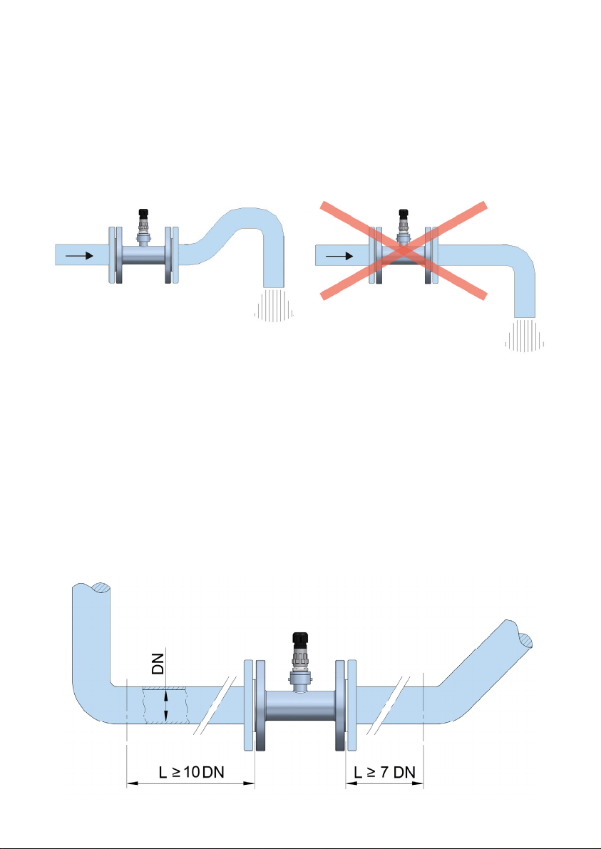
When the flow measurement is to be made before an open discharge, it is necessary to
install the flowmeter in a section of pipe with a trap which avoids the presence of air inside
the meter.
3.3 Position
The installation and position of the turbine flowmeter can be either vertical, horizontal or
inclined. Make sure that the flow direction is as marked by the arrow on the turbine body.
3.4 Straight pipe sections
To obtain good readings, turbulences must be avoided. For this it is necessary to have
straight sections of pipe upstream and downstream of the turbine. The straight pipe
sections must be of the same internal diameter as the turbine and the minimum lengths
must be the following:
Upstream 10 DN
Downstream 7 DN
These sections must be free of deviations or disturbing elements (valves etc.).
5
Page 6
These distances can be reduced by installing a flow straightener upstream of the turbine
at a distance equivalent to 5 DN.
3.5 Valves
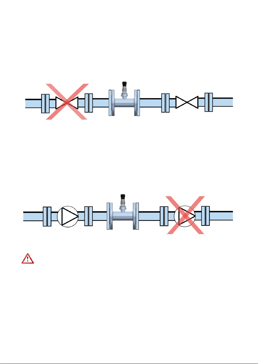
Regulating or shut-off valves must always be installed after the turbine, in order to assure
that pipe is full of liquid.
3.6 Pumps
Pumps must always be installed before the turbine in order to avoid cavitation.
This way the presence of air pockets in the flowmeter is avoided, which could cause
unbalance of the propeller which could damage the turbine.
Note: To avoid cavitation the pressure at the outlet of the turbine should be higher than
twice the pressure loss of the turbine (see table Nº 2) plus 1.25 times the vapour pressure
of the liquid or its most volatile component.
6
Page 7
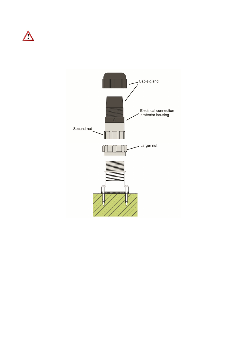
3.7 Electrical connection
It is important to keep the connecting cable between the flowmeter and the auxiliary
electronics away from mains or power supply cables, in order to avoid interferences. In
any case, those should be separated at least 5 cm.
The turbine flowmeter has an IP65 connector fastened to the counter by means of 4
screws. The connector consists of 3 parts joined by threaded nuts. (See figure).
Loosening the larger nut in the middle of the connector allows us to withdraw the half
where the cable will be later soldered.
The other half of the connector is fixed to the counter and should not be removed, except
when servicing the detector (See point 4.5 of the MAINTENANCE section).
The removable part of the connector consists of the cable gland at the top and the
electrical connection protector housing.
Before starting the installation, check that the cable gland is the right size for the cable to
be used. This will guarantee the instrument will stay watertight. The cable gland used is
for cables with outside diameters between 6 mm and 10 mm.
The electrical connection protector housing is dismounted by loosening the second nut.
When this is removed, the three connector terminals are visible.
7
Page 8

The terminals are numbered 1 to 3 and the connection is as follows:
Nº 1: Ground
Nº 2: Coil
Nº 3: Coil
Before soldering the connections, unscrew the cable gland and feed it, together with the
electrical connection protector housing, over the cable.
The joint between the cable and the connector should always be soldered, and should be
tidy and without short circuits between terminals.
Peel the outside insulation to free the inner cables. It is recommended to tin the ends of
the wires to avoid loose ends.
Once the connections have been made, the housing should be mounted screwing it on
and then the cable gland should be tightened to avoid entry of any liquid or humidity.
Once assembled the half of the connector, the mounting in the base has only one position
defined by the keyway between the two parts.
Check that the rubber seal is in its position inside the connector base. If this is the case,
introduce the connector half in the base, positioning by the keyway, and screw on the nut
until the end of the thread is reached.
4 MAINTENANCE
The simple construction of the TM turbine results in a long life in normal working
conditions.
The life of the parts depends mainly on the abrasive characteristics of the product to be
measured and the maximum flow rate.
The combination of these two factors make it difficult to estimate the life of the
components in good working conditions.
If the maximum flow rates given for each DN in the following table are exceeded the life is
considerably reduced.
Flow ranges
DN
15
20
25
40
50
65
80
100
125
150
Minimum flow
rate (m³/h)
0,3 3 7500 5
0,6 6,8 7500 8
0,9 13,5 7000 16
1,9 30 5600 40
5 50 2800 60
9 90 2400 115
15 150 3100 180
28 280 4500 340
45 450 2400 560
65 650 2500 820
Maximum flow
rate (m³/h)
Pressure drop (mm H20) at
maximum flow rate
8
Maximum intermittent
flow rate (m³/h)
Page 9

The only parts that may need periodical maintenance are the propeller shaft and bearing.
The rest of the pieces will only need maintenance when there is chemical attack or
abrasion by the fluid being measured.
It has been confirmed that the life of these parts under normal working conditions is longer
than 20.000 hours.
4.1 Disassembly
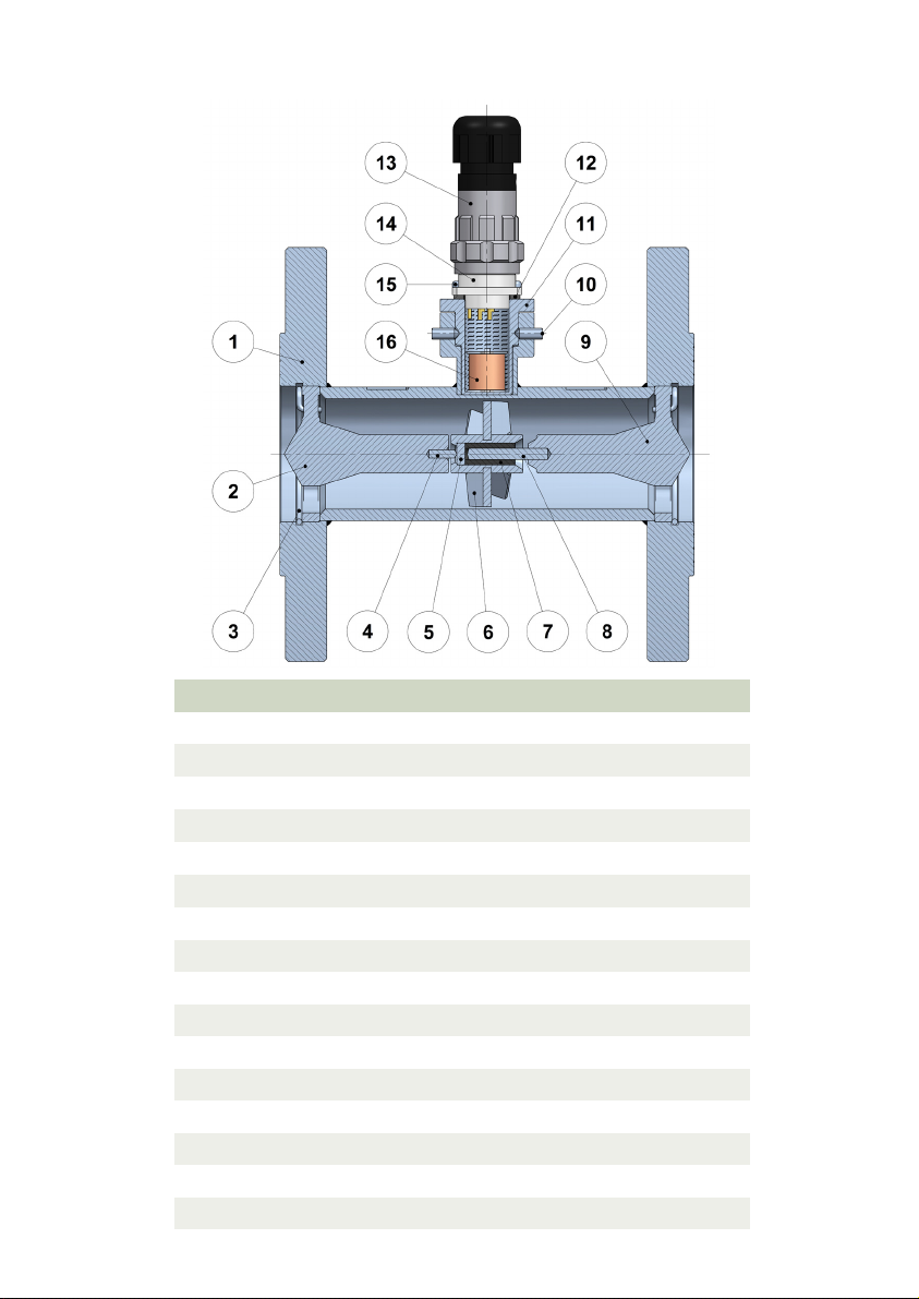
The numbering of the different elements corresponds to the table and drawing in the
“Parts List” section on Page 10.
Inside the metering tube (1) are located the deflectors (2) (9) and the propeller (6). The
inlet deflector (2) has a stop (4) inserted and the outlet deflector (9) has a shaft (8).
The deflectors are dismounted by withdrawing the circlips (3) which hold them in. They
are mounted at about 5 mm from the ends of the metering tube and are easily removed
with a screwdriver.
Remove the circlip of the outlet deflector. Place the turbine in a horizontal position and
withdraw the deflector. The propeller assembly will come out together with the deflector.
Remove the circlip at the other end and withdraw the inlet deflector.
4.2 Cleaning
The propeller assembly contains the bearing (7) and the tungsten disk (5). These must
not be disassembled.
To clean the inside of the bearing use a cloth or soft paper wrapped around a fine shaft;
do not use abrasive elements. Cleaning liquids can be used to help remove dirt or grease.
To clean the propeller shaft (6) clean with a cloth soaked in alcohol, soapy water or
solvent. The propeller should rotate freely on the shaft but should not be loose. It should
not have a play of more than 1 part in 50 of the shaft diameter.
The rest of the pieces can be cleaned with the same products.
4.3 Mounting
Before starting to mount the turbine make sure that all the pieces are completely dry, with
this we can prevent the propeller shaft from seizing.
The turbine should be mounted as follows:
Slide the inlet deflector (2) in its place (use the flow direction arrow to determine the
correct end) and fix it with a circlip (3).
Fit the propeller assembly on the shaft (8) of the outlet deflector (9).
With the metering tube (1) in a horizontal plane introduce the outlet deflector assembly
and fix it with a circlip (3).
Check that the assembly is not loosen and that the two circlips are correctly seated. There
should only be about 0,5 mm axial play of the propeller assembly on its shaft.
The turbine is ready for installation and operation.
4.4 Pickup
To determine if the pickup group is working properly, the impedance between terminals 2
and 3 of the base connector (14) have to be measured with a multimeter. The value
should be between 1500 and 2500 Ohm.
4.5 Replacing the pickup
The female plug (13), as indicated in the Installation section, can be removed from the
base (14) by unscrewing the larger nut. The male connector base is fixed to the coil
support (11).
Unscrew the female connector in order to separate the cable and after that unscrew the
pickup group from the turbine metering tube (1).
To insert a new pickup group, follow the inverse process.
9
Page 10
5 PART LIST
Nº Description Material
1
2
3
4
5
6
7
8
9
10
Measuring tube EN 1.4404
Inlet deflector EN 1.4404
Circlip EN 1.4401
Stop Tungsten
Disc Tungsten
Propeller EN 1.4016
Bearing Graphite
Shaft Tungsten
Outlet deflector EN 1.4404
Screw DIN 913 M4 x 8 EN 1.4301
11 Pickup group EN 1.4305
12
Gasket NBR
13 Female connector Aluminium alloy
14
Male connector Aluminium alloy
15 Screw DIN 7985 M3 x 8 EN 1.4301
16
Pickup —
10
Page 11
6
TECHNICAL DATA
Accuracy
± 0.5% measured value
Repeatability
± 0.1% measured value
Temperature
Process temperature:
-50 ºC … +170 ºC
Ambient temperature:
-20 ºC ... +60 ºC
Connections
EN 1092-1 flanges. Other flange standards.
BSP or NPT threaded connections
Sanitary couplings according to ISO 2852, SMS 1145, DIN 11851, TRI-CLAMP®
Materials
Body: EN 1.4404 (AISI 316L)
Propeller: EN 1.4016 (AISI 430)
Working pressure
DN15 ... DN50: PN40
DN65 ... DN150: PN16
Others on request
Electrical connection
By means of IP65 connector.
Signal amplitude
> 15 mV, proportional to flow rate
Recommended cable
Shielded bifilar up to 30 m length.
NOTE: For distances up to 100 m the APTM44 amplifier shall be used.
Conforms with the Pressure Equipment Directive 97/23/EC.
This equipment is considered as being a pressure accessory and NOT a safety accessory
as defined in the 97/23/CE directive, Article 1, paragraph 2.1.3.
Associated electronics
CIP / CIP II: Battery powered volumetric counter.
CP ... CH420: 2-wire analog transmitter with flow rate and volume indication.
MC01: Flow rate and volume indicator with relay output for batching.
MT02: Volume counter with relay output for batching.
DFD2: Frequency divider.
CI420: Analog transmitter.
APTM44: Pulse converter for the pickup signal.
HART protocol optional.
11
Page 12
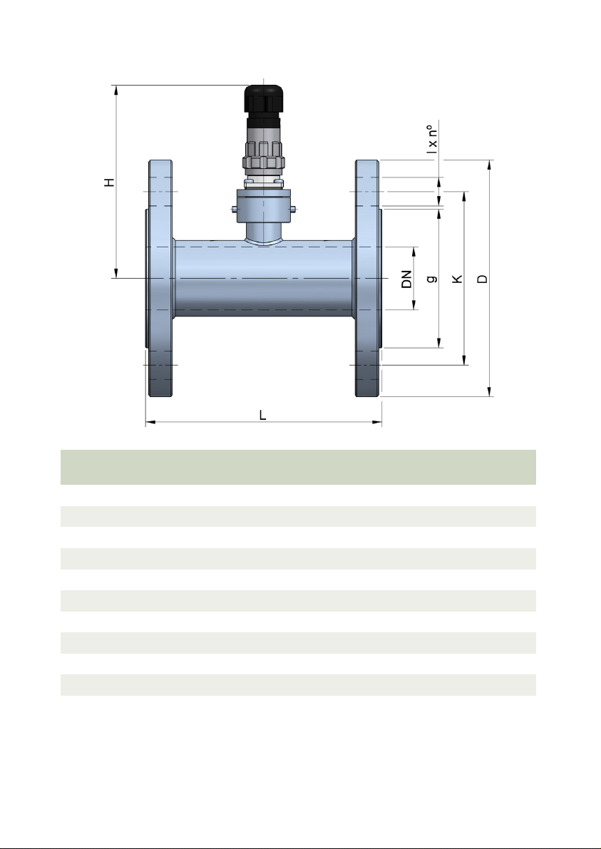
7 DIMENSIONS AND WEIGHTS
DN
15
20
25
40
50
65
80
100
125
150
* 18 x 4 in case of DIN 2501 flanges
PN
(flanges)
40 95 65 45 14 x 4 100 115 2,0
40 105 75 58 14 x 4 100 115 2.5
40 115 85 68 14 x 4 130 120 3,5
40 150 110 88 18 x 4 150 125 5,0
40 165 125 102 18 x 4 150 130 7,0
16 185 145 122 18 x 8 * 160 140 10,0
16 200 160 138 18 x 8 160 145 12,0
16 220 180 158 18 x 8 250 155 17,0
16 250 210 188 18 x 8 280 170 21,0
16 285 240 212 22 x 8 300 180 27,0
D K g l x nº
12
H
L
(max)
Weight
(kg)
Page 13
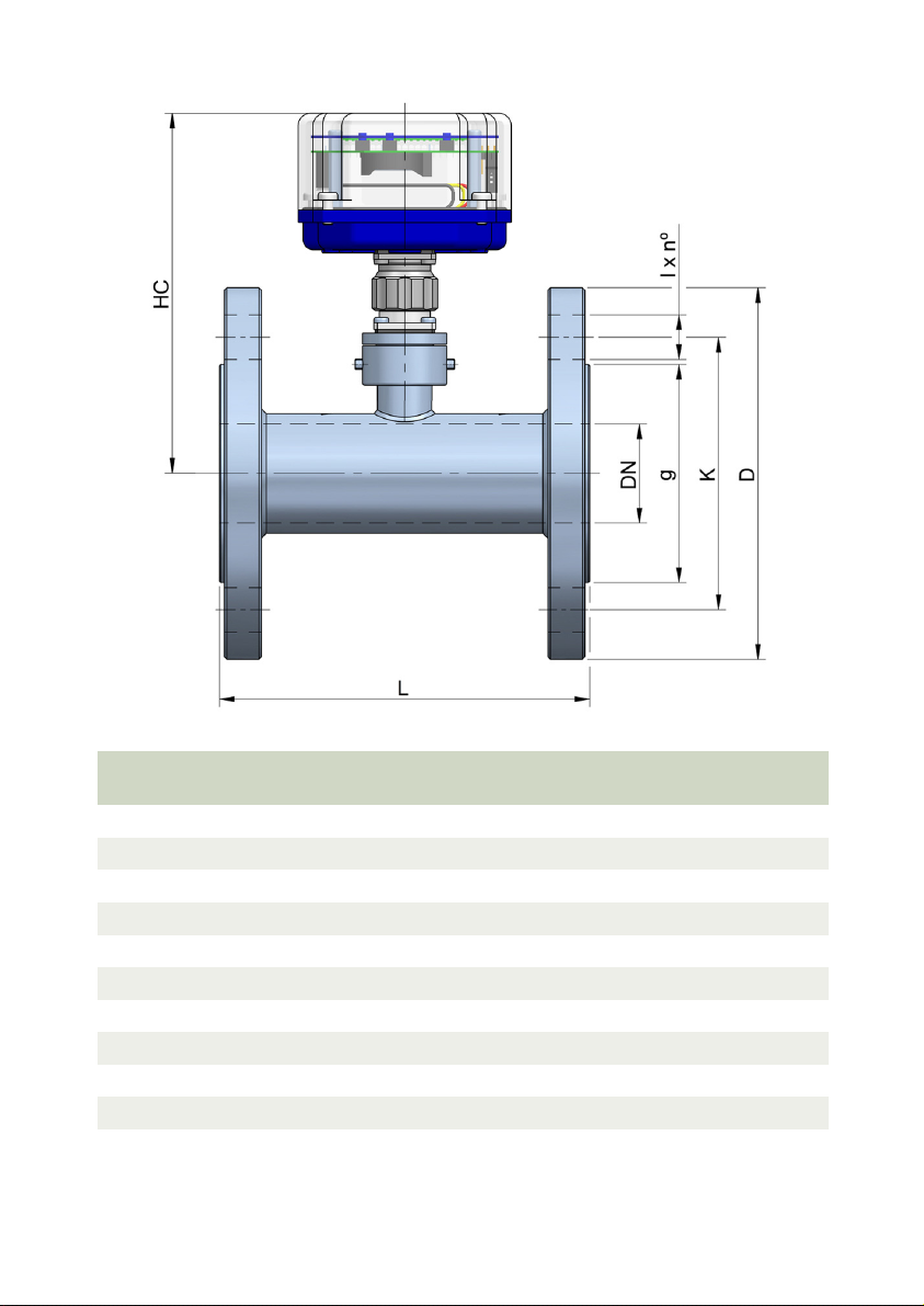
DN
15
20
25
40
50
65
80
100
125
150
PN
(flanges)
D K g l x nº
40 95 65 45 14 x 4 100 140 2,2
40 105 75 58 14 x 4 100 140 2.7
40 115 85 68 14 x 4 130 145 3,7
40 150 110 88 18 x 4 150 150 5,2
40 165 125 102 18 x 4 150 155 7,2
16 185 145 122 18 x 8 * 160 165 10,2
16 200 160 138 18 x 8 160 170 12,2
16 220 180 158 18 x 8 250 180 17,2
16 250 210 188 18 x 8 280 195 21,2
16 285 240 212 22 x 8 300 205 27,2
* 18 x 4 in case of DIN 2501 flanges
13
HC
L
(max)
Weight
(kg)
Page 14

8 K FACTOR (PULSES / LITRE)
DN
15
20
25
40
50
65
80
100
125
150
Measured values for water at 20 ºC
Pulses / litre
± 10%
730 1,28
500 2
220 4,5
60 16
20 50
10 100
5 200
3 333
1,5 666
0,8 1250
cm3 / pulse
± 10%
9 ADDITIONAL INSTRUCTIONS FOR THE ATEX VERSION
This chapter only applies to equipment intended for use in explosive atmospheres.
9.1 Intrinsic safety
The flowmeters of series TM, when include just the pickup sensor and the connector, can
be considered simple apparatus as defined in the EN 60079-11 standard. In these cases it
can be installed in hazardous areas provided that they are connected to a zener barrier or
to an intrinsic safety isolator. Please consult factory for the recommended models.
9.2 Flameproof enclosure
These equipment conform with the directive 94/9/CE (Equipment and protective systems
intended for use in potentially explosive atmospheres) as indicated in the EC-type
examination certificate LOM 14ATEX2008 X and its marking.
Given that this instrument belong to group II, it is intended for use in places likely to
become endangered by explosive atmospheres, but not in mines.
The category is 2GD, that is, it is intended for use in areas in which explosive
atmospheres caused by mixtures of air and gases, vapours, mists or air/dust mixtures are
likely to occur.
14
Page 15
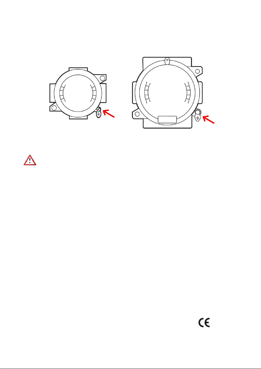
9.2.1 Facilities connecting conductive parts to earth
When the instrument is not grounded securely through the connection process, it should
be grounded through the housing screw, as shown in the figure.
9.2.2 Maintenance
NOTE: When the flameproof enclosure contains an electronics model CIP or CIP II, it
should never be opened in presence of explosive atmosphere.
For the rest of models, before any maintenance that involves opening the flameproof
enclosure, make sure there is no voltage in any of internal components.
The is no special maintenance for the ATEX version.
9.2.3 Technical data for the ATEX version
Temperature
Ambient temperature: -20 ... +60 ºC
Electrical connection
Inside the flameproof enclosure.
Recommended cable
The standard thread supplied for the cable gland connection is 3/4” NPT.
ATEX cable glands for non-armoured or armoured cables can be placed .
The outer diameter of the cables that fits the 3/4” NPT cable glands is between 6 and 21
mm.
Associated electronics
CIP / CIP II: Battery powered volumetric counter.
CP ... CH420: 2-wire analog transmitter with flow rate and volume indication.
Conforms to 94/9/EC Directive (equipment and protective systems intended for use in
potentially explosive atmospheres).
The rest of characteristics are the same as in the point 6.
HART protocol optional.
15
Page 16

9.2.4 Marking
The marking of the equipment shows the following characteristics:
- Manufacturer
- Model
- Serial number (year of construction and number)
- CE marking
- ATEX marking
- Certification number
- Address of the manufacturer
16
Page 17
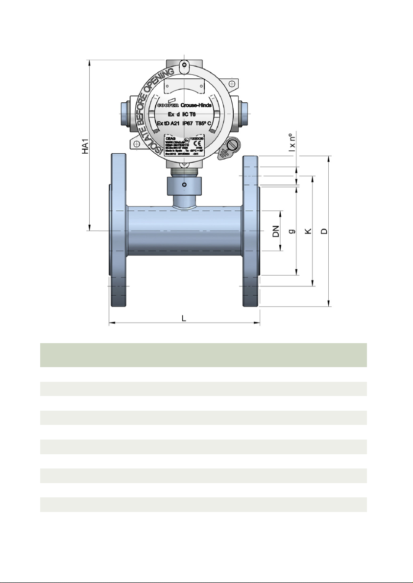
9.2.5 Dimensions and weights
DN
15
20
25
40
50
65
80
100
125
150
PN
(flanges)
D K g l x nº
40 95 65 45 14 x 4 100 160 2,5
40 105 75 58 14 x 4 100 160 3.0
40 115 85 68 14 x 4 130 165 4,0
40 150 110 88 18 x 4 150 170 5,5
40 165 125 102 18 x 4 150 175 7,5
16 185 145 122 18 x 8 * 160 185 10,5
16 200 160 138 18 x 8 160 190 12,5
16 220 180 158 18 x 8 250 200 17,5
16 250 210 188 18 x 8 280 215 21,5
16 285 240 212 22 x 8 300 225 27,5
* 18 x 4 in case of DIN 2501 flanges
17
HA1
L
(max)
Weight
(kg)
Page 18
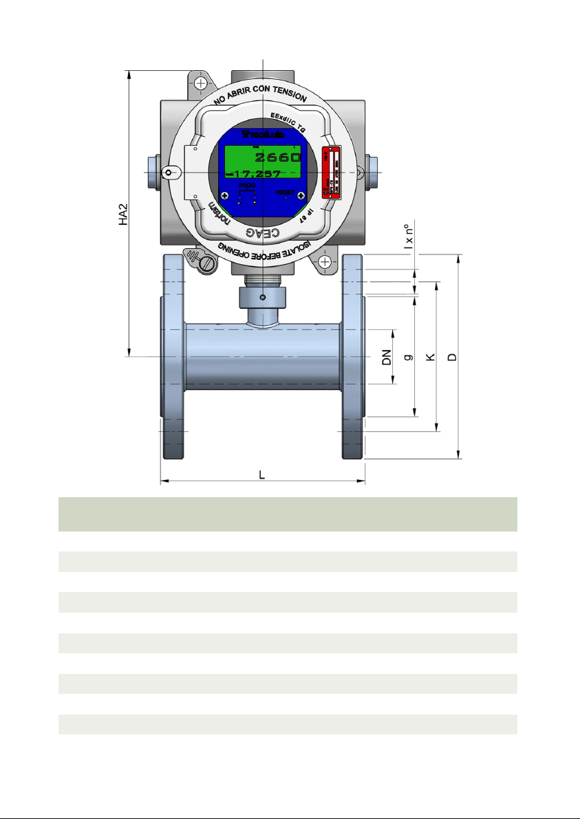
DN
15
20
25
40
50
65
80
100
125
150
PN
(flanges)
D K g l x nº
40 95 65 45 14 x 4 100 205 3,5
40 105 75 58 14 x 4 100 205 4.0
40 115 85 68 14 x 4 130 210 5,0
40 150 110 88 18 x 4 150 215 6,5
40 165 125 102 18 x 4 150 220 8,5
16 185 145 122 18 x 8 * 160 230 11,5
16 200 160 138 18 x 8 160 235 13,5
16 220 180 158 18 x 8 250 245 18,5
16 250 210 188 18 x 8 280 260 22,5
16 285 240 212 22 x 8 300 270 28,5
* 18 x 4 in case of DIN 2501 flanges
18
HA2
L
(max)
Weight
(kg)
Page 19

TROUBLESHOOTING
10
Problem Probable cause Solution
The associated
electronics does not
totalize
The associated
electronics totalize less
than the actual volume
The associated
electronics totalizes
more than the actual
volume
The flow rate indicated by
the associated equipment
is unstable
Blockage or friction of the
turbine propeller by particles
Damaged pickup Change the pickup
Disconnected cables between
the turbine and the associated
electronics
Blockage or friction of the
turbine propeller by particles
Presence of air pockets
Excessive emptying of storage
tanks
The pipe is not completely full
Straight pipe sections before
and after the flowmeter have not
been kept
Install a filter according to
specification (maximum mesh
size = 200 µm).
Check the cable connection
Install a filter according to
specification (maximum mesh =
200 µm).
Control the minimum tank level.
Provide an air degasser
upstream of the turbine if air
intakes can be expected.
Make sure that the pipe is
completely full, for example,
installing the flowmeter in a
vertical pipe with upwards flow
Check that there are enough
straight pipe sections as
indicated in point 3.4.
19
Page 20

WARRANTY
Tecfluid S.A. guarantees all the products for a period of 24 months from their sale, against all faulty
materials, manufacturing or performance. This warranty does not cover failures which might be
imputed to misuse, use in an application different to that specified in the order, the result of service
or modification carried out by personnel not authorized by Tecfluid S.A., wrong handling or
accident.
This warranty is limited to cover the replacement or repair of the defective parts which have not
damaged due to misuse, being excluded all responsibility due to any other damage or the effects
of wear caused by the normal use of the devices.
Any consignment of devices for repair must observe a procedure which can be consulted in the
website www.tecfluid.com, “After-Sales” section.
All materials sent to our factory must be correctly packaged, clean and completely exempt of any
liquid, grease or toxic substances.
The devices sent for repair must enclose the corresponding form, which can be filled in via website
from the same “After-Sales” section.
Warranty for repaired or replaced components applies 6 months from repair or replacement date.
Anyway, the warranty period will last at least until the initial supply warranty period is over.
TRANSPORTATION
All consignments from the Buyer to the Seller´s installations for their credit, repair or replacement
must always be done at freight cost paid unless previous agreement.
The Seller will not accept any responsibility for possible damages caused on the devices during
transportation.
TecfluidS.A.
NarcísMonturiol33
08960SantJustDesvern
Barcelona
Tel:+34933724511
QualityManagementSystemISO9001cerfiedby
PressureEquipmentDirecve97/23/CEcerfiedby
ATEXEuropeanDirecve94/9/CE
cerfiedby
Fax:+34934734449
tecfluid@tecfluid.com
HART®isaregisteredtrademarkofHARTCommunicaonFoundaon
www.tecfluid.com
Thetechnicaldatadescribedinthismanualissubjecttomodificaonwithoutnoficaonifthetechnicalinnovaonsin
themanufacturingprocessessorequire.
20
 Loading...