

Page 1
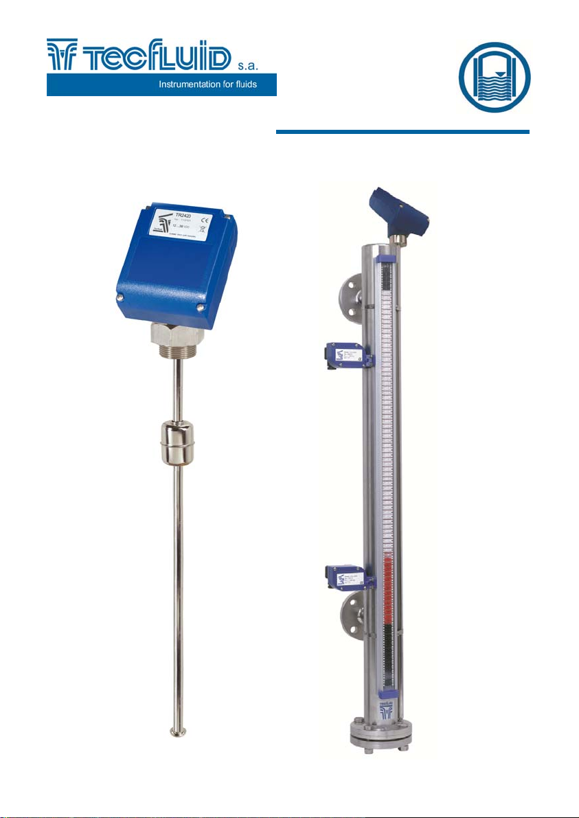
Level transmitter
TR2420
for series
LE / LT
Instructions Manual
R-MI-TR2420 Rev.: 0 English version
1
Page 2

TABLE OF CONTENTS
1. INTRODUCTION ...................................................................................... 3
2. RECEPTION ............................................................................................ 3
3. ELECTRICAL CONNECTION ................................................................. 3
4. OPERATION ............................................................................................ 4
5. MAINTENANCE ....................................................................................... 9
6. TECHNICAL CHARACTERISTICS ......................................................... 10
6.1 Power supply .............................................................................. 10
6.2 Output .......................................................................................... 10
6.3 General characteristics .............................................................. 10
6.4 Safety characteristics ................................................................ 10
6.5 Minimum PC requirements for Winsmeter TR ......................... 10
7. DIMENSIONS .......................................................................................... 11
2
Page 3
1. INTRODUCTION
The level transmitter TR2420 is a converter that adapts to the level resistive sensors
series LE and LT (reed chain).
The variation of the internal resistance of the sensor, as the float changes its position, is
converted into a current signal from 4 to 20 mA.
2. RECEPTION
The level transmitters series TR2420 are supplied ready for installation and operation.
Likewise, they are packaged for protection during transportation and storage.
3. ELECTRICAL CONNECTION
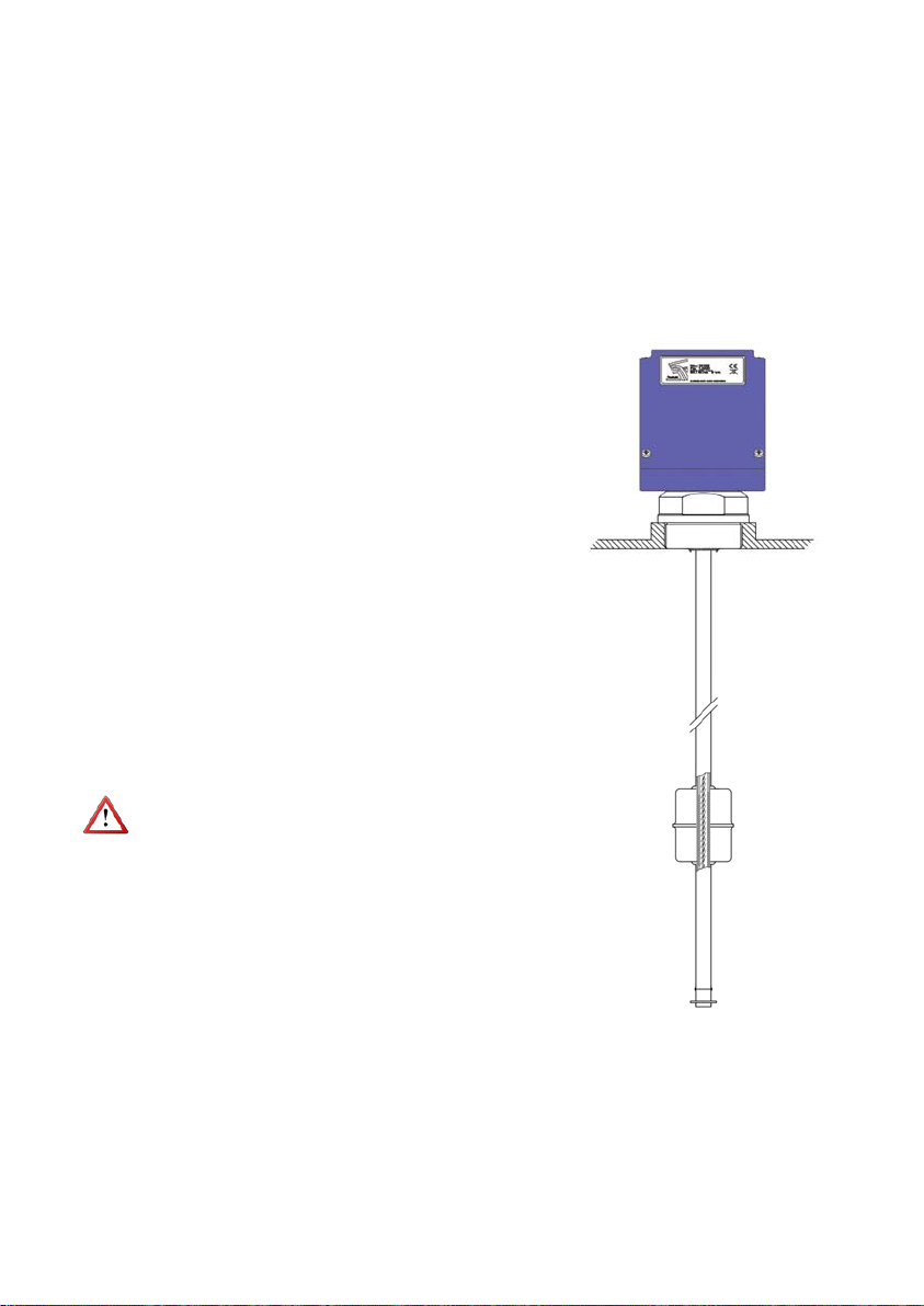
In order to access inside the transmitter, remove
the cover by unscrewing the four screws.
For the electrical connection, the transmitter
TR2420 has a screw terminal block.
For the electrical installation it is recommended
to use multiple conductor cables with individual
cable sections in the order of 0.25 to 0.5 mm
order to make it easier to connect.
Before starting the installation, check that the
cable glands are the right size for the cables to
be used, this will guarantee the instrument will
stay watertight. The PG11 cable glands used are
for cables with outside diameters between 6 mm
and 10 mm.
Peel the outside insulation to free the inner
cables. Pass the cables through the cable glands
and screw down in the corresponding positions
of the terminal strip.
Once the wiring is finished make sure that the
cables are well gripped by the cable glands to
maintain the degree of protection.
Before installing the equipment, check that the
supply voltage available in the installation is
compatible with the marked on the label of the
instrument. The power supply limits are indicated
in the label of the equipment.
To help in the connecting of the equipment, the
description of the terminals is marked on the
printed circuit next to the terminal block.
2
in
3
Page 4
4. OPERATION
The transmitter TR2420 is delivered already programmed so that the analog
output indicates 4 mA when the float is in the lowest level, and 20 mA when it is in the
highest level.
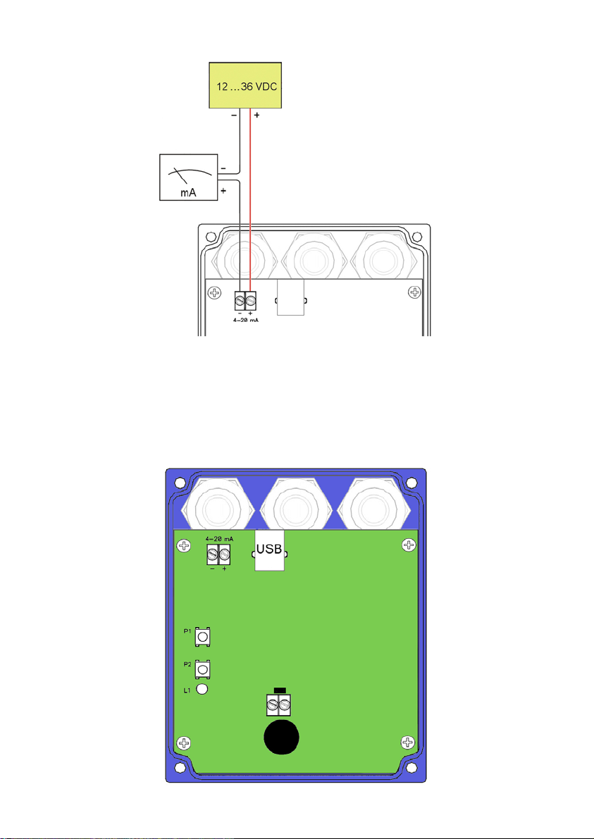
Write protect jumper
4
Page 5
If this setup must to be changed, one may proceed in two different ways as follows:
a) Directly with the instrument.
When opening the box cover of the transmitter, 2 push buttons (P1 and P2) and a LED
indicator (L1) can be seen, as shown in page 4.
P1 is the 4 mA programming push button. Likewise P2 is the 20 mA programming push
button.
The push buttons are protected by a pulse time. A short press, less than two seconds, will
not program the instrument.
With the transmitter powered and the write protect jumper placed (page 4), move
the float to the point where you want to transmit 4 mA. Press P1 until the red LED flashes.
Move the float to the point where you want to transmit 20 mA. Press P2 until the gree n
LED flashes.
Check the operation with a multimeter.
5
Page 6
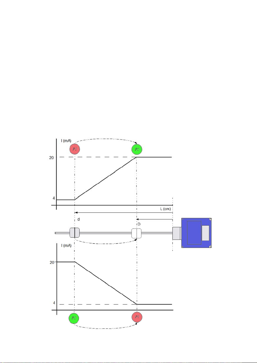
The following drawing shows an example of two situations. In the first case, 4 mA are
at the bottom, and 20 mA at the top. In the second case the 20 mA are at the bottom.
b) Using Winsmeter TR PC program.
Steps in the preceding paragraphs can be done by means of the device associated
software Winsmeter TR, which allows working in a more comfortable and intuitive way.
The software can be downloaded from the following link of the Tecfluid S.A. website.
www.tecfluid.com/downloads/winsmet erTR.zip. Extrac t the files fr om the winsmeterTR.zip
to a new system folder.
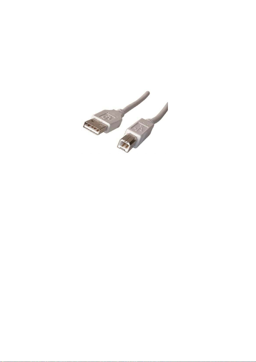
USB type A, to type B.
In order to connect the converter to a comp uter an USB c able is re quired. This ca ble is type
A at one end and type B at the other, and it is readily available on any supplier of computer
products.
When the cover of the transmitter is opened, there is a USB connector. Connect the B
type side to the transmitter and the A type side to the computer. Power the transmitter up.
Run the file WinsmeterTR.exe. No drivers for the level transmitter are needed. The
program Winsmeter TR automatically recognizes the device by clicking on the "Port"
section.
Open the device.
By means of the software, various functions can be performed. The way in which the
functions are grouped is the following in terms of access by operators.
a) Always accessible. Anyone can access the Visualization tab.
Visualization of the 4-20mA loop status.
Visualization of the distance equivalent to the level.
b) Accessible only by authorized users by means of password.
The password can be configured by the operator and prevents these parameters are
changed accidentally. The default password is program.
6
Page 7
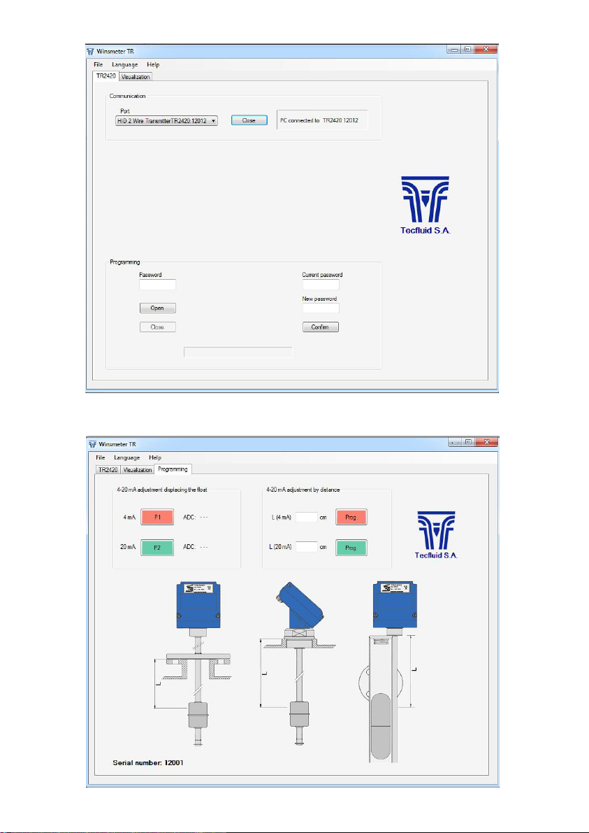
The password can be changed by entering the current password and the new
password in the appropriate sections.
7
Page 8
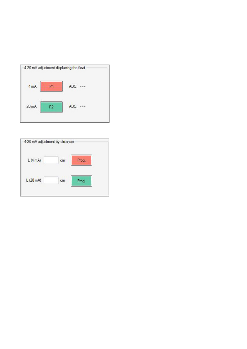
To do any programming of the transmitter, enter the password and click the button
"Open."
The tab “Programming” will be added to the screen. Accessing this tab, the following
functions are available:
- Configuration of points P1 and P2 that define the range of the current loop by
moving the float.
4-20 mA loop adjustment by moving the float.
Move the float to the position where 4 mA are
required. Press P1 on the computer screen.
Move the float to the position where 20 mA are
required. Press P2 on the computer screen.
Be sure that the LED corresponding to the button
lights steady for 2 seconds.
4-20 mA loop adjustment by distance.
Introduce the distance L, in centimeters, where 4 mA
are required in “L (4 mA)“ and press the red button.
Introduce the distance L, in centimeters, where 20
mA are required in “L (20 mA)“ and press the green
button.
Be sure that the LED corresponding to the button
lights steady for 2 seconds.
- Configuration of current range defining the distances equivalent to the level.
After configuring the current loop, it is recommended to go to the tab "Visualization" and
check its operation. This tab allows to check the current loop and the distance L.
If the operation is successful, go to the tab "TR2420", close the port and then disconnect
the level transmitter from the computer.
Verify that the loop current indicates the current value accordingly.
If it is necessary to change the factory settings of the transmitter, it is recommended to
set the current loop values directly with the transmitter or via PC, making the 4-20
mA adjustment by moving the float.
If the instrument is a by-pass level gauge Series LT, it is possible that the float can not be
moved, since it is within the level. If you
it is recommend the 4-20 mA loop adjustment by distance, with the PC software.
want to change the 4-20 mA loop factory settings,
8
Page 9
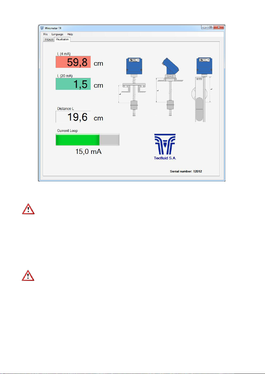
Case LE
Level with flange: L = distance in centimeters between the floating level and the bottom of
Level with thread: L = distance in centimeters between the floating level and the top of the
Case LT
L = distance in centimeters between the floating level of the float and the bottom of the
transmitter base.
IMPORTANT:
The USB connection is only used for configuration and operation of the device, in no way
is intended to be used continuously, as a normal mode of operation in an industrial
environment.
the flange.
thread.
5. MAINTENANCE
No special maintenance is required.
9
Page 10

6 TECHNICAL CHARACTERISTICS
6.1 Power supply
2 wire system
Minimum voltage: 0.02 Z + 12 (Volt) (Z is the load in the current
The minimum value is 12 VDC for Z=0 Ohm.
Maximum voltage: 36 VDC
Consumption: maximum 20 mA
6.2 Output
Analog output: 4 - 20 mA, factory calibrated
Possibility of readjusting the current range.
Maximum load in the 4-20 loop: 1.1 k (at 36 VDC supply voltage)
6.3 General characteristics
Housing ingress protection: IP67
Cable glands: PG11
Ambient temperature: -5 ...+70 ºC
Resolution: 10 mm
Maximum distance 6 m
6.4 Safety characteristics
Material conforms to the following directives:
2004/108/EC Electromagnetic compatibility.
2002/96/EC Waste electrical and electronic equipment
6.5 Minimum PC requirements for Winsmeter TR
Operating system: Windows XP, Windows Vista or Windows 7
CPU: Pentium 3, 500 MHz
System memory (RAM): 256 MB
Hard disk: 40 MB of free space
loop in Ohm).
10
Page 11
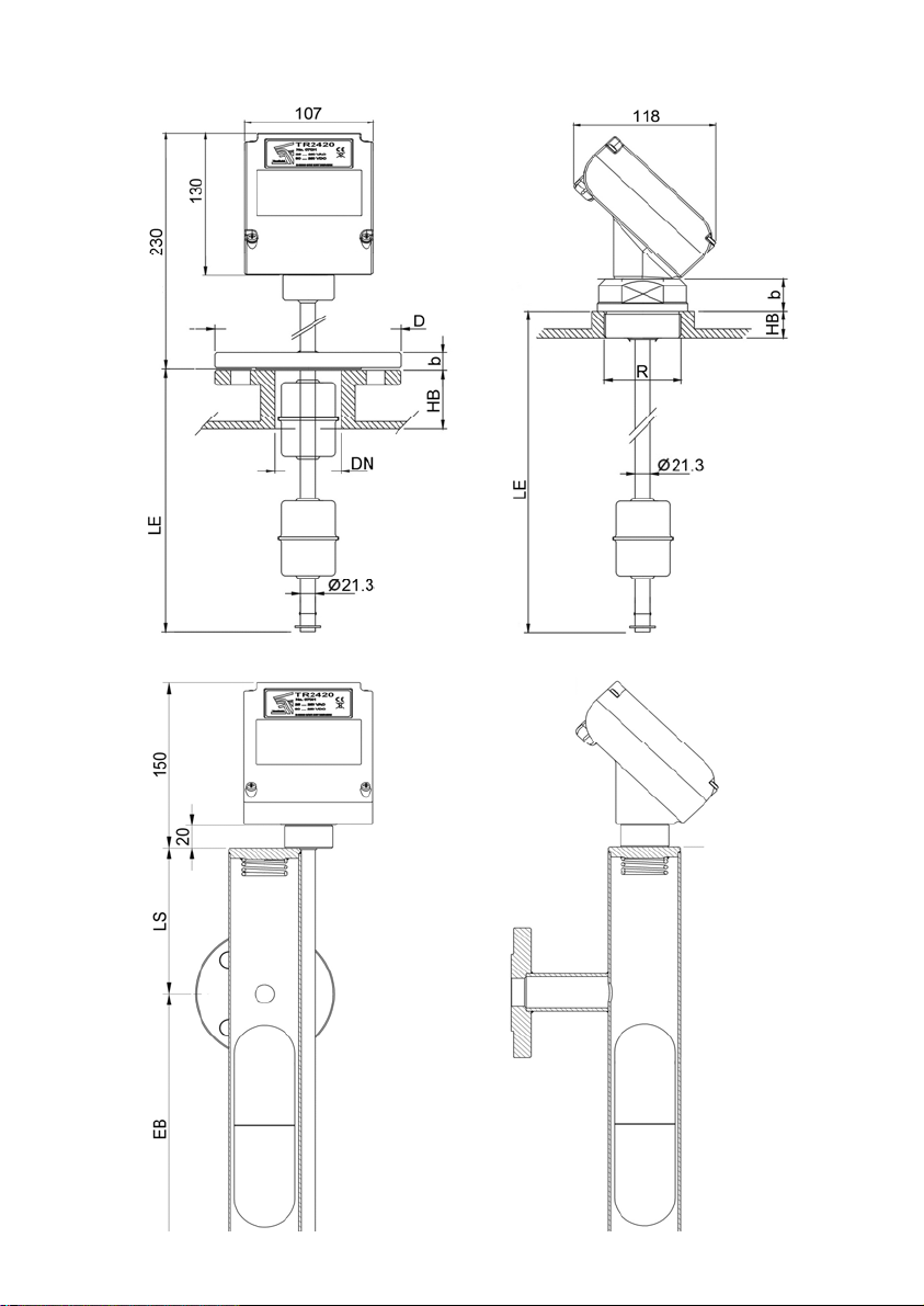
7 DIMENSIONS
11
Page 12

WARRANTY
Tecfluid S.A. guarantees all the products for a period of 24 months from their sale, against all faulty
materials, manufacturing or performance. This warranty does not cover failures which might be
imputed to misuse, use in an application different to that specified in the order, the result of service
or modification carried out by personnel not authorized by Tecfluid S.A., wrong handling or
accident.
This warranty is limited to cover the replacement or repair of the defective parts which have not
damaged due to misuse, being excluded all responsibility due to any other damage or the effects
of wear caused by the normal use of the devices.
Any consignment of devices for repair must observe a procedure which can be consulted in the
website www.tecfluid.com, “After-Sales” section.
All materials sent to our factory must be correctly packaged, clean and completely exempt of any
liquid, grease or toxic substances.
The devices sent for repair must enclose the corresponding form, which can be filled in via website
from the same “After-Sales” section.
Warranty for repaired or replaced components applies 6 months from repair or replacement date .
Anyway, the warranty period will last at least until the initial supply warranty period is over.
TRANSPORTATION
All consignments from the Buyer to the Seller´s installations for their credit, repair or replacement
must always be done at freight cost paid unless previous agreement.
The Seller will not accept any responsibility for possible damages caused on the devices during
transportation.
12
 Loading...