

Page 1
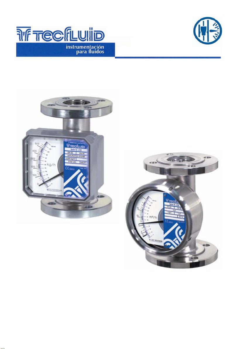
Variable Area
Flow Meter
Series
SC-250
Instructions Manual
The following users manuals are included:
AMM Limit Switch Users Manual
AMD Limit Switch Users Manual
TKEX Transmitter Users Manual
HALLTEC III TEH, TTEH Transmitters Users Manual
HALLTEC III EEx Transmitters Users Manual
TP-1200 Pneumatic Transmitter Users Manual.
C-MI-09 Rev.: 4 English Version
Page 2
Technical Data
• Accuracy: Based on VDE / VDI 3513
± 2,5% of full scale value.
On Order:
± 1,6% of full scale value.
• Rangeability: 10:1
• Scale length: ~100 mm.
• Scales: Direct in l/h etc. or in %.
• Mounting: Vertical.
Rising flow direction.
• Pipe fittings: DIN flanges.
Others on order.
• Materials: EN 1.4404 (AISI-316L), PVC, PTFE,
PP.
• Working pressure :
- SC-250 EN 1.4404
PN 40 DN 15...DN 50
PN 16 DN 65...DN 150
- SC-250 PVC / PTFE / PP
PN 16 DN 15...DN 50
PN 10 DN 65...DN 150
- SC-250 EN 1.4404+PVC / PTFE / PP
PN 40 DN 15...DN 40
PN 16 DN 50...DN 125
PN 10 DN 150
Others on order.
• Working temper ature:
Standard:
- EN 1.4404: -50ºC...+200ºC
- PVC: 0ºC...+ 50ºC
- PTFE: -20ºC...+150ºC
With thermal separator:
• Indicator housing:
• Mounting length:
• Conforms with the Pressure Equipment
Directive 97/23/EC.
This equipment is considered as being a pressure
accessory and NOT a safety accessory as defined
!
in the 97/23/EC directive, Article 1, paragraph
2.1.3.
• Optional limit switches:
• Maximum current: 3A.
• Maximum voltage: 250 Vac.
- PP: -20ºC...+ 85ºC
- EN 1.4404: -180ºC...+400ºC
IP 65, Polyamide 11 covered aluminium
DN 15...DN 125: 250 mm.
DN 150: 300 mm.
- SC-AMM
Micro-switch mounted in the indicator
housing.
Conforms with Directive 73 / 23 / EEC
(Low Voltage)
2
- SC-AMD
DIN 19234 (NAMUR) vane operated
inductive detector, mounted in the
indicator housing.
• Nominal voltage: 8,2 Vdc
Conforms with Directive 89/336/EEC
(EMC)
• Optional transmitters:
- TKEX Angular position converter, coupled to the
indicating system of the flow meter, which
gives a linear output 0...4-20 mA
proportional to the measured flow rate.
• Power supply: 12,7...36 Vdc.
• Output signal: 0...4-20 mA.
• Electrical connection: 2, 3 ó 4 wire.
Certified by PTB to EEx ia IIC T6.
- TEH3 A position transducer with
analog output for 2 or 4 wire connection.
• Power supply: 10 to 50 Vdc (2 wire)
220 Vac, 240 Vac, 110 Vac, 24 Vac
50/60 Hz (4 wire)
• Output signal: 4-20 mA.
Conforms with Directives 73 / 23 / EEC
(Low voltage) and 89/336/EEC (EMC)
- TTEH3 A position transducer with analog
output and totalizer for 2 or 4 wire
connection.
• Power supply: 10 to 50 Vdc (2 wire)
220 Vac, 240 Vac, 110 Vac, 24 Vac
50/60 Hz (4 wire)
• Output signal: 4-20 mA.
Conforms with Directives 73 / 23 / EEC
(Low voltage) and 89/336/EEC (EMC)
- TEH3/EEX A position transducer with
analog output for 2 wire connection.
• Power supply: 10 to 24 Vdc
• Output signal: 4-20 mA.
Conforms with Directives 89/336/EEC
(EMC) and 94 / 9 / CE (ATEX)
Certified by LOM to EEx ia IIC T4
- TTEH3/EEX A position transducer with analog
output and totalizer for 2 wire connection.
• Power supply: 10 to 24 Vdc
• Output signal: 4-20 mA.
Conforms with Directives 89/336/EEC
(EMC) and 94 / 9 / CE (ATEX)
Certified by LOM to EEx ia IIC T4
- TP1200
Pneumatic transmitter that gives an
output of 3-15 psi or 0,2-1 bar
proportional to the measured flow rate.
• Air supply: 1,4 bar ±0,1 bar
Page 3
g
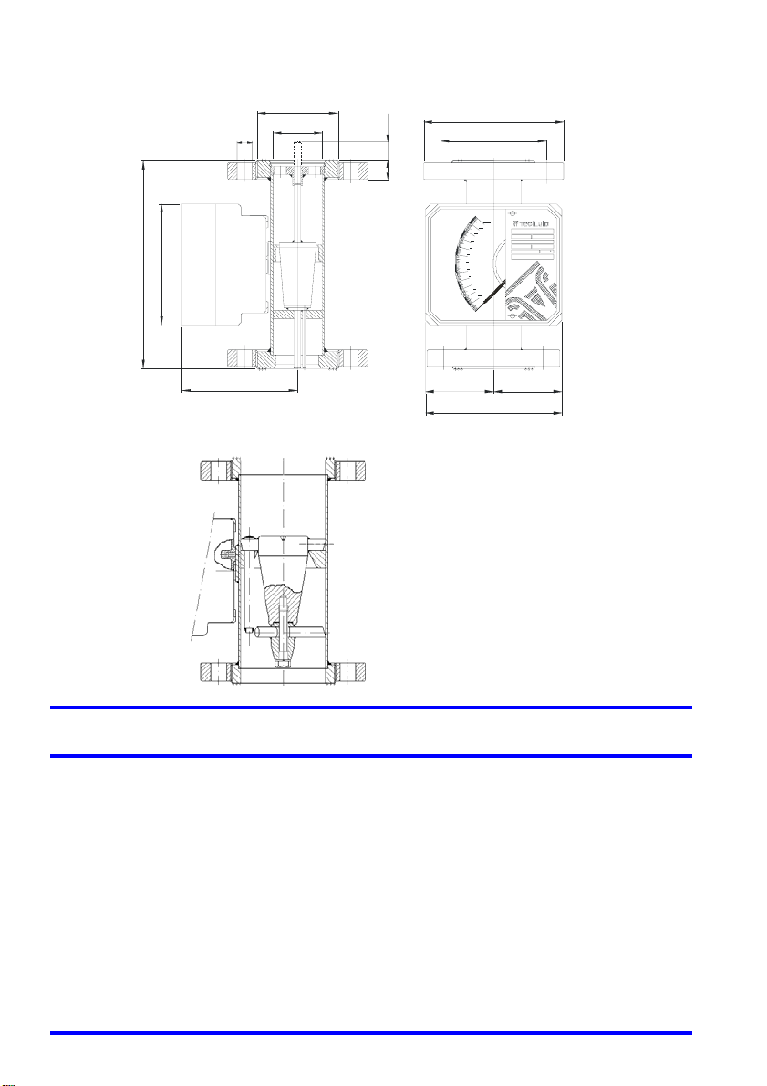
Flow Meter Dimensions with DIN 2501 Flanges
DN-15 to DN-80
ø
DN
ø l
L
145
C max.B
ø D
ø k
Serie SC-2 50
DN PN
m.Pa.s.
kg/l
C
bar
item
A
= =
160
DN-100 to DN-150
DN D k g l x nº B Flange
A C L
PN
15 95 65 45 14 x 4 16 40 116 45 250
25 115 85 68 14 x 4 18 40 124 45 250
40 150 110 88 18 x 4 18 40 130 45 250
50 165 125 102 18 x 4 20 40 136 45 250
65 185 145 122 18 x 4 18 16 140 45 250
80 200 160 138 18 x 8 20 16 148 45 250
100 220 180 158 18 x 8 20 16 156 - 250
125 250 210 188 18 x 8 22 16 168 - 250
150 285 240 212 22 x 8 22 16 182 - 300
3
Page 4
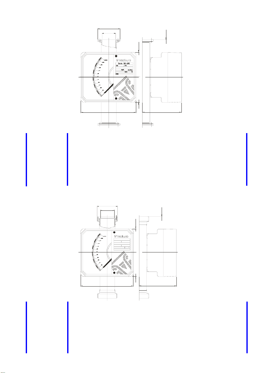
Flow Meter Dimensions with CLAMP ISO 2852 Pipe Fittings
Ø D
Ø B
145
250
EN 1.4404 (AISI-316L)
160
A
Nominal DN 15 15 25 40 50 65 80 100 125 150
Nominal Pipe Ø
(exterior)
21,3 (33,7) 40 51 63,5 70 88,9 114.3 139,7 168,3
Ø B 19,3 31,3 37,6 48,6 60,3 66,8 84,9 110,3 135,7 163,1
Ø D 34 50,5 50,5 64 77,5 91 106 130 155 183
A 112 116 124 130 136 140 148 156 168 182
Flow Meter Dimensions with DIN 11851 Pipe Fittings
Ø D
Ø B
145
Serie SC-250
DN PN
kg/l
m.Pa.s.
C
bar
item
160
250
A
EN 1.4404 (AISI-316L)
Nominal DN 15 15 25 40 50 65 80 100 125 150
NW Fitting 20 25 40 50 65 65 80 100 125 150
Ø B 20 26 38 50 66 66 81 100 125 150
Ø D
Rd 34
x 1/8”
Rd 52
x 1/6”
Rd 65
x 1/6”
Rd 78
x 1/6”
Rd 95
x 1/6”
Rd 95
x 1/6”
Rd 110
x 1/4”
Rd 130
x 1/4”
Rd 160
x 1/4”
A 112 116 122 126 138 138 146 155 168 180
4
Rd 190
x 1/4”
Page 5
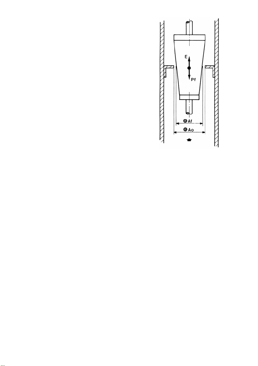
Working principle
The flow meter consists of a calibrated orifice and a
conical float. The rising flow pushes the float to an
equilibrium point. The area obtained between the float
and the orifice is proportional to the flow rate.
This type of measuring principle is known as variable
area.
The equilibrium point depends on :
− The float weight : Pf
− The fluid thrust : E
− The free flow area : Al
The area proportional to the flow rate will be:
Al = Ao - Af
where:
Ao = Area of calibrated orifice
Af = Float area
RECEPTION
The SC-250 series flow meters are supplied tested in our calibration rigs, ready for installation and
service.
The instruments are supplied packed for their protection during transport and storage. Likewise
they have blocking elements that should be removed before installation.
With the instrument in a vertical position, check that the float moves freely and that the indicating
needle, starting from zero, follows the float movements over the whole scale and returns to zero.
The float displacement should be done manually without jerks, with the flow meter in a VERTICAL
position and the zero of the scale at the bottom.
FLOW METER INSTALLATION. (Figures 1, 2, 3 & 4)
The flow meter must be installed in a vertical position with rising flow direction.
It is important that the position is completely vertical, given that deviations of about 5º can produce
errors of about 8-10% of the reading due to friction on the float.
In the case of an installation with horizontal flow direction, the flow meter should be installed as
shown in figure 1.
In the case of an installation with vertical falling flow direction, the flow meter should be installed as
shown in figure 2.
5
Page 6
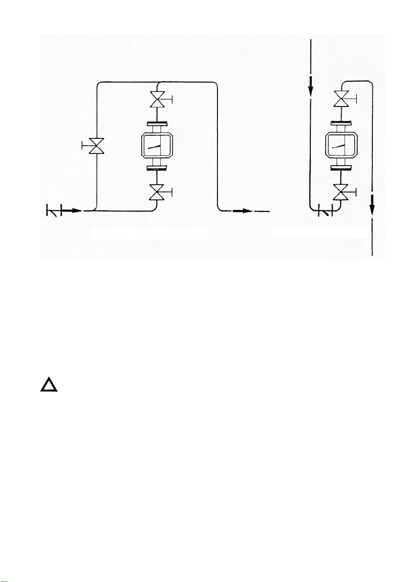
HORIZONTAL FLOW DIRECTION
FALLING FLOW DIRECTION
Figure 1
Figure 2
If the fluid to be measured is a liquid, it is advisable to install a regulating valve BEFORE the flow
meter (Figure 4).
In GAS measurements it is recommended to install the valve AFTER the flow meter, in this way
the working pressure can be kept the same as the calibration pressure. (Figure 3).
If the outlet after the valve is at atmospheric pressure, the valve should be closed until a back
pressure of at least the float’s pressure drop is obtained.
Valves should always be opened slowly to avoid water hammers
!
FILTERS
The installation of a filter before the instrument is important, this will avoid possible obstructions
and breakdowns in the measuring system.
The mesh of the filter should be 1,5—2 mm.
In the case of having abundant magnetic particles in suspension, it is necessary to mount a
magnetic filter at the inlet to the instrument to avoid the accumulation of particles in the float’s
magnetic field, with the possibility of immobilising it.
6
4
Page 7
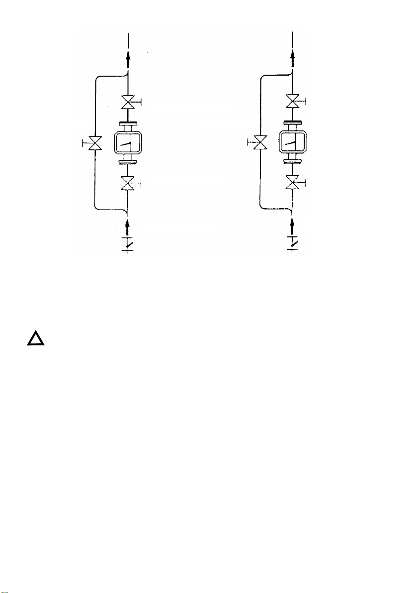
VALVULA DE
SHUT OFF
2.
2.
CIERRE
VALVE
VALVULA DE
REGULATOR
1.
1.
REGULACION
VALVE
INSTALACION PARA
INSTALLATION
LIQUIDOS
FOR LIQUIDS
VALVULA BY-PASS
BY-PASS VALVE
3
3
VALVULA DE REGULACION
REGULATOR VALVE
2.
2.
VALVULA DE CIERRE
SHUT OFF VALVE
1.
1.
INSTALACION PARA GASES
INSTALLATION FOR GASES
Figura 3
Figure 3
VALVULA BY-PASS
BY-PASS VALVE
3
3
Figura 4
Figure 4
OPERATION
Once the meter is installed, the regulator valve should be opened slowly. The fluid flow will move
the float which, through magnetic coupling, moves the indicating needle.
Any variations of working conditions with respect to those when calibrated can induce
!
reading errors. The calibration working conditions are indicated on the instrument’s face
plate.
GAS MEASUREMENT. (Figure 3)
THE WORKING PRESSURE IS OF MAXIMUM IMPORTANCE for correct GAS measurement as
it directly affects the scale readings.
Therefore if a meter is calibrated for 2 bar and it’s working at 1 bar there will be an error of 22%.
In order for the meter to work at the calibration pressure (nominal working pressure) and to obtain
a back pressure that will maintain the float equilibrium, the regulating valve should be mounted as
shown in Figure 3.
The flow should be controlled by the meter outlet valve, while keeping the inlet one fully open. The
by-pass valve should be fully shut off.
If the regulation is done using the inlet valve, in open circuits or at low gas flow in the meter, the
gas will expand which will sharply diminish its density, giving very serious reading errors.
If the flow is regulated by the inlet valve, the float usually experiences an oscillating movement
which produces a shut off action until sufficient pressure is gained to overcome its weight. The
sudden fall of pressure, when the gas escapes, will make it fall. This cycle is repeated until the
valve is closed or is sharply and fully opened and then closing the valve until it takes it back to the
desired flow rate.
This does not mean that this phenomenon will not occur again if the flow is continued to be
regulated by the inlet valve.
7
Page 8
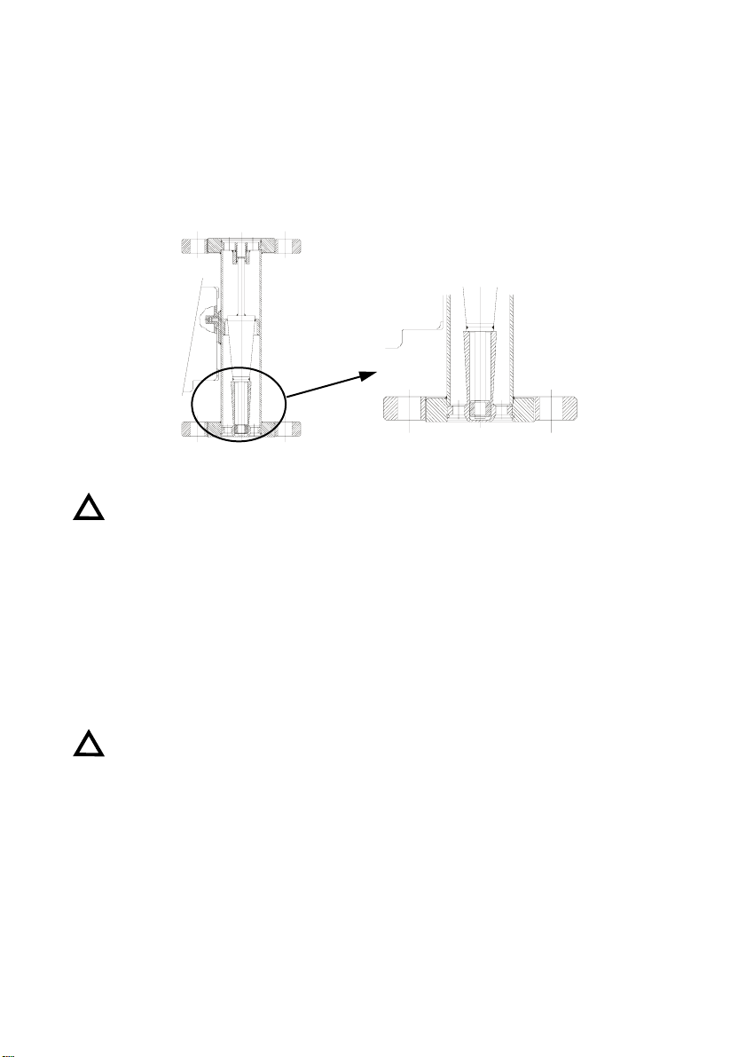
When measuring low pressure gas flow with AISI 316 floats, oscillation of the float often occurs,
which makes it very difficult to read the flow rates. In these cases it is recommended to install a
damper in the instrument.
The damper consists of a piston mounted in the interior of closed cylinder at one end. The
compression forces of the gas absorb the floats oscillations, maintaining it stable in the reading
point.
If you have this problem, consult us to install a damper in your flow meter.
!
LIQUID MEASUREMENT.
When measuring liquids the regulation valve should be installed as shown in Figure 4.
The by-pass valve should remain closed. The inlet valve (1) is opened slowly to low flow rate
position, then the meter outlet valve (2) is also opened slowly so as to get rid of the air and then
progressively fully opened.
The required flow is then regulated by using the inlet valve.
!
A FILTER PRIOR TO THE METER IS RECOMMENDED. If the fluid also contains magnetic
particles, which could adhere to the float and jam it, a magnetic filter must be placed at the meter
inlet.
The valves must be closed during work stoppages or at the end of the working day to
avoid sudden surges on starting up, which could damage or bend the float when
forcibly driven during fluid flow.
Close the valves during work stoppages or, at the end of the working day to stop sudden
surges when started up. If the float hits the stops sharply this could cause damage to the
meter.
8
Page 9
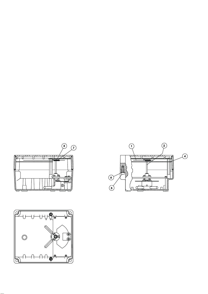
MECHANICAL MAINTENAN CE
Indicating housing
If operating anomalies are detected with the meter, the following points should be checked. If
necessary disassemble the front cover which is held by four M5 Allen screws (5) and plastic
washers (6) for the hermetic seal, at the back of the indicating housing.
1. THE INDICATOR NEEDLE (1) RUBS ON THE READING SCALE (4).
This normally happens if the meter has been hit or dropped. Simply straighten it out by bending it
slightly until it is separated by between 2-3 mm from the reading scale surface (4)
2. THE INDICATOR NEEDLE (1) DOESN’T READ 0 ON THE SCALE.
For this, the meter should be placed in its real working position on top of a NON-MAGNETIC
table. If when the float is moved the needle moves but does not return to 0, check that the needle
hub (3) is firmly attached to the pointer shaft (2). If it isn’t, secure the needle hub (3) onto the
conical tip (2) of the shaft by tapping it lightly and carefully.
This may have happened during haulage or through the meter being dropped, make the indicator
needle coincide with 0 using the frontal adjusting screw (7) on the indicator needle, screw to left or
right wherever convenient. Make sure that the shaft (2) is held fast so as not to be bent or
damaged
Check that there is no rubbing between the needle movement system and limit switch or
transmitter connecting cables .
This way the flow meter will be properly adjusted to give correct readings.
9
Page 10
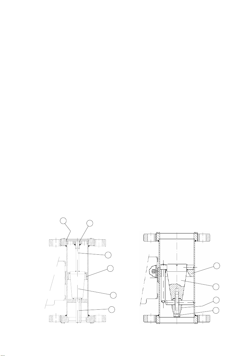
Metering Tube
1. JAMMED FLOAT
The possible cause in DN-15 to DN-80 floats (5) is that the top central guide rod (3) or the bottom
one (6) is bent by a water hammer. To solve this, extract the float (5) from the flow meter removing
the circlip (1) which locks the top float stop (2). Next remove the float stop (2). The float can now
be extracted. Align the guide rods and manually check that the movement is good without rubbing.
To re-assemble the float again in the flow meter, reverse the aforementioned process.
With the DN-100 to DN-150 floats (5), the cause can be that the lateral guide rod is bent or dirty.
To solve this, extract the float (5) from the flow meter removing the screw (8) which holds the float
end (7). Next remove the float end. The float can now be extracted from the top of the flow meter.
Straighten or clean the guide rod.
To re-assemble the float again in the flow meter, reverse the aforementioned process.
Apart from this, the float can jam for other reasons:
Accumulated metallic dirt due to the float magnetic field. In this case dismount the float (5)
following the aforementioned instructions, clean it and, at the meters inlet, install a magnetic filter
or a normal one depending on the size of the particles.
Adhered chemical dirt. Clean with suitable products or solvents and soft brushes, NEVER WITH
METALLIC UTENSILS.
Top float stop (2) bent by water hammer. If it is possible, straighten it and check alignment.
Otherwise change it for a new one.
2. LACK OF MAGNETIC FIELD
Disassemble the float (5) as indicated in point 1. Check to see if the float has suffered chemical
aggression and the permanent MAGNET has been affected. If this is the case, the float must be
changed and the flow meter will have to be re-calibrated.
10
1
2
3
4
5
6
4
5
7
8
Page 11
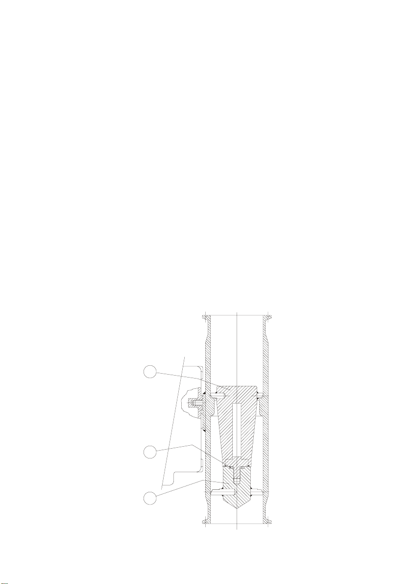
3. CALIBRATED ORIFICE (4)—CONICAL FLOAT (5)
Check their mechanical state for scratching, impact or chemical attack. If the float is in bad
condition it must be changed. If the calibrated orifice is damaged the metering tube and the float
must be changed. In both cases the flow meter has to be re-calibrated.
Float for sanitary use
Two special tools are necessary to disassemble the float (5) from the flow meter. They can be
supplied on demand by TECFLUID, S.A.
These tools fit into the lateral guides of the float (5) and of the end of the float (7).
Once the tools have been fitted into their respective guides, turn the float’s end as if it were a nut.
That way the float will be separated from the float end, and the float can be taken out of the top of
the meter and the float end from the bottom of it.
Cleaning of the inside of the flow meter and/or the float can be effected when this is disassembled.
Clean with suitable products and soft brushes, NEVER WITH METALLIC UTENSILS.
To re-assemble the float again in the flow meter, reverse the aforementioned process, making sure
that the O ring (6) is correctly placed between the float and the floats end. Tighten the float end
moderately onto the float.
If you are interested in acquiring the special TECFLUID tools please indicate for which nominal
diameter they are required.
5
6
7
11
Page 12

WARRANTY
Tecfluid S.A. GUARANTEES ALL ITS PRODUCTS FOR A PERIOD OF 24 MONTHS, after
consignment, against all defects in materials and workmanship.
This warranty does not cover failures which can be imputed to misuse, use in an application different to
that specified in the order, the result of service or modification by un-authorized persons, bad handling
or accident.
This warranty is limited to cover the repair or replacement defective parts which have not been
damaged by misuse.
This warranty is limited to the rep air of t he e quipme nt a nd all f urthe r and eventuall y foll owing dama ges
are not covered by this warranty.
Any consignment of equipment to our factory or distributor must be previously authorised. The
consignment should be done with the equipment well packed, clean of any liquids, grease or
hazardous materials. Tecfluid S.A. will not accept any responsibility for damage done during transport.
Together with the equipment, a note should be enclosed indicating the failure obs erved, the name,
address and telephone number of the sender.
TECFLUID S.A.
Narcís Monturiol, 33
E-08960 Sant Just Desvern
Tel. + 34 933 724 511 - Fax + 34 934 734 449
E-mail: [email protected]
Internet: www.tecfluid.com
The technical data in this pamphlet is subject to modification without notification, if the technical innovations in the product or
manufacturing processes so require.
 Loading...