

Page 1
1
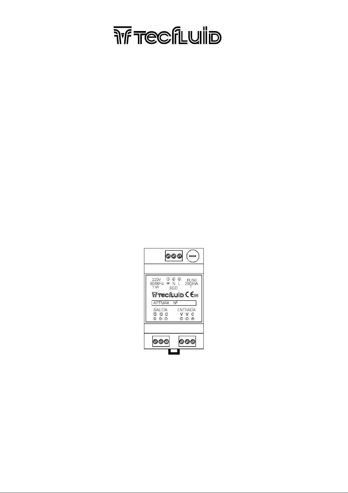
APTM44 AMPLIFIER USERS MANUAL
TABLE OF CONTENTS
1 WORKING PRINCIPLE
1.1 Limitations
1.2 Applications
............................................................................................................... 2
....................................................................................................................... 2
..................................................................................................................... 2
2 INSTALLATION
2.1 Power Supply Connection
2.2 Pick-up Input Connection
2.3 Pulse Output Connection
............................................................................................................................. 2
............................................................................................. 3
.............................................................................................. 3
.............................................................................................. 3
3 WORKING
...................................................................................................................................... 4
4 TECHNICAL CHARACTERISTICS
4.1 Environment
4.2 Mains supply
4.3 Pulse Output
4.4 Pulse Input
4.5 Dimensions
.................................................................................................................... 4
.................................................................................................................... 4
.................................................................................................................... 4
....................................................................................................................... 4
...................................................................................................................... 5
.............................................................................................. 4
Cod.:E-MI-2152004I / Rev.: 1
Page 2

2
1 WORKING PRINCIPLE
The amplifier for the TM-44 is designed to avoid problems of electrical interferences in
installations where the turbine is located at a big distance from the electronic control equipment.
The turbine pick-up generates very low level pulses (in the mV range). Given that the instrument
input must detect these low level pulses, it is very susceptible to electrical interferences, especially to
mains interferences. The probability of being affected by interferences increases with the length of the
cable between the pick-up and the instrument.
The APTM44 amplifier converts the pulses from the turbine pick-up into two TTL level signals
which are out of phase. This output signal is compatible with the pick-up input circuit of Tecfluid
instruments and it appreciably increases the rejection of interferences which can be picked up by a long
cable.
2.1 Limitations
The maximum frequency should be less than 1500 Hz.
2.3 Applications
a). The elimination of interferences in long cables between the turbine and the control
instrument.
b). Signal conditioning for instruments not provided with a pick-up input. One of the TTL outputs
can be used as an input for an industrial robot etc.
c). For connecting two or more pick-up input instruments to the same turbine.
3 INSTALLATION
The APTM44 is housed in an IP40 plastic case for mounting inside an electrical control panel.
The case has a clip for mounting on DIN 46 277 or DIN EN 50 022 rails.
Cod.:E-MI-2152004I / Rev.: 1
Page 3

3
The connection is by means of screw terminal blocks.
The APTM44 should be installed as close as possible to the turbine in order to reduce to a
minimum the length of the pick-up cable.
IMPORTANT : In order to comply with the electrical safety requirements as per IEC 1010-1, the
installation of the equipment must take into account the following:
-The equipment must be installed inside an electrical mounting cabinet to avoid the possibility
that the operator may touch a connection terminal.
-A mains switch must be provided to disconnect the equipment. This switch must be marked as
the disconnecting device for the equipment and be within easy reach of the operator.
4.1 Power Supply Connection
The power supply should be connected to terminals Nº 2 and 3.
4.3 Pick-up Input Connection
These cables should not pass close to AC mains cables, given that these can produce
interferences in the input and induce errors.
The input should be connected as follows:
APTM44 Terminal Nº Turbine Terminal Nº
4 Shield 1 Shield
5 live 2 live
6 live 3 live
The "live" cables are the ends of the pick-up coil.
4.5 Pulse Output Connection
There are two ways of connecting the pulse output, depending on the type of input available:
4.6.1 Output for a Pick-up Input
This output produces two TTL level outputs which are opposed in phase.
APTM44 Terminal Nº MC-01 (TM-44) Terminal Nº
7 Shield 1 Shield
8 live 2 or 3 live
9 live 3 or 2 live
4.6.3 Output for TTL Input
APTM44 Terminal Nº MT-02 (TTL) Terminal Nº
7 Shield 1 Shield
8 live 2 live
Cod.:E-MI-2152004I / Rev.: 1
Page 4

4
5 WORKING
The APTM44 needs no adjusting to adapt to the pick-up or control instrument.
In the event that there are pulse outputs with no flow in the turbine, what is most probable is that
the cables to the pick-up are too long or that they are too near mains cables.
7 TECHNICAL CHARACTERISTICS
8.1 Environment
The plastic case has protection as per IP 40 and the terminals as per IP 20.
The working temperature limits are 0 to 50
o
C
8.3 Mains supply
The standard mains voltage is 220 Vac 50/60 Hz. AC Mains voltages of 240 V, 110 V y
24 V 50/60 Hz. and 24 Vdc supply voltage are available on order.
The power consumption is less than 1 W.
The instrument is not supplied with a mains filter and in the exceptional cases that, due to high
levels of mains interference, a mains filter is needed, this must be installed externally. Due to the low
power consumption, almost any small mains filter will be adequate.
8.5 Pulse Output
The output pulse has a pulse width of 1 ms.
The TTL outputs are directly from a CMOS integrated circuit and have a load current of 1 mA
maximum.
8.7 Pulse Input
The input is intended for an inductive pick-up coil.
The maximum input frequency is about 1500 Hz.
Cod.:E-MI-2152004I / Rev.: 1
Page 5
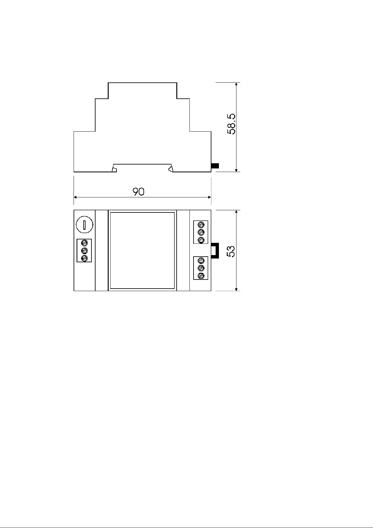
8.9 Dimensions
The weight of the instrument is about 200 g.
5
Cod.:E-MI-2152004I / Rev.: 1
Page 6

6
WARRANTY
Tecfluid S.A. GUARANTEES ALL ITS PRODUCTS FOR A PERIOD OF 24 MONTHS, after
consignment, against all defects in materials and workmanship.
This warranty does not cover failures which can be imputed to misuse, use in an application different to
that specified in the order, the result of service or modification by un-authorized persons, bad handling or
accident.
This warranty is limited to cover the repair or replacement defective parts which have not been damaged
by misuse.
This warranty is limited to the repair of the equipment and all further and eventually following damages
are not covered by this warranty.
Any consignment of equipment to our factory or distributor must be previously authorised. The
consignment should be done with the equipment well packed, clean of any liquids, grease or hazardous
materials. Tecfluid S.A. will not accept any responsibility for damage done during transport.
Together with the equipment, a note should be enclosed indicating the failure observed, the name,
address and telephone number of the sender.
TECFLUID S.A.
Narcís Monturiol, 33
Tel. + 34 933 724 511 - Fax + 34 934 734 449
E-08960 Sant Just Desvern
E-mail: [email protected]
Internet: www.tecfluid.com
Cod.:E-MI-2152004I / Rev.: 1
 Loading...