

Page 1
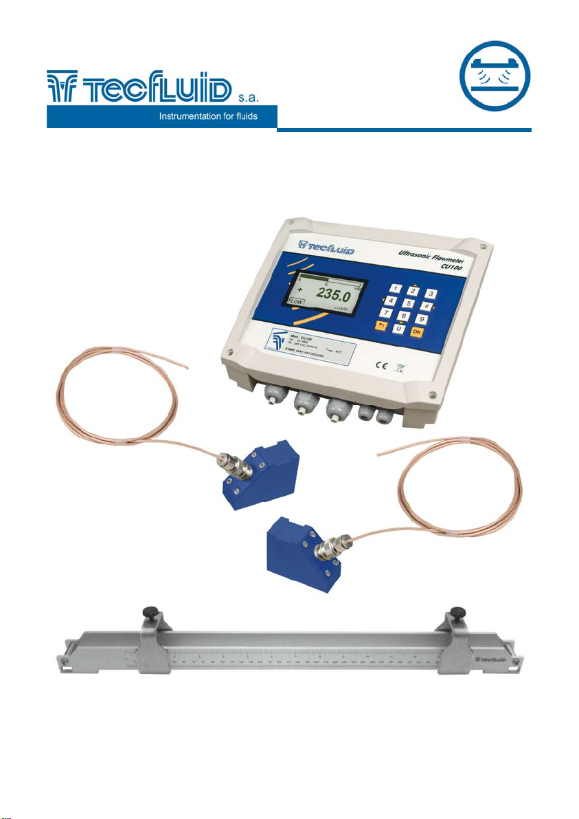
Ultrasonic
flowmeter
CU100
Instruction manual
R-MI-CU100 Rev.: 1 English version
Page 2

PREFACE
Thank you for choosing the flowmeter CU100 of Tecfluid S.A.
This instruction manual allows the installation and operation of the
ultrasonic flow meter CU100. It is recommended to read it before
using the equipment.
WARNINGS
This document shall not be copied or disclosed in whole or in
any part by any means, without the written permission of
Tecfluid S.A.
Tecfluid S.A. reserves the right to make changes as deemed
necessary at any time and without notice, in order to improve
the quality and safety, with no obligation to update this manual.
Make sure this manual goes to the end user.
Keep this manual in a place where you can find it when you
need it.
In case of loss, ask for a new manual or download it directly
from our website www.tecfluid.com Downloads section.
Any deviation from the procedures described in this instruction
manual, may cause user safety risks, damage of the unit or
cause errors in the equipment performance.
Do not modify the equipment without permission. Tecfluid S.A.
is not responsible for any problems caused by a change not
allowed. If you need to modify the equipment for any reason,
please contact us in advance.
2
Page 3

TABLE OF CONTENTS
1 INTRODUCTION ................................................................................... 5
2 INSTALLATION OF THE ELECTRONIC CONVERTER ...................... 5
2.1 Electrical connection ............................................................... 6
2.1.1 Power supply wiring .................................................. 7
2.1.2 Relay output wiring .................................................... 7
2.1.3 Analog output wiring .................................................. 8
2.1.4 Transducers wiring .................................................... 9
3 CONVERTER INTERFACE .................................................................... 10
4 MAIN MENU .......................................................................................... 11
4.1 Passwords to access the menus ............................................ 11
5 TRANSDUCERS INSTALLATION ........................................................ 13
5.1 Straight pipe run requirement ................................................. 13
5.2 Installation with the alignment guide ..................................... 16
5.2.1 Straps preparation ..................................................... 16
5.3 Fastening of the transducers .................................................. 16
5.4 Entering the installation parameters of the transducers ...... 17
5.5 Language .................................................................................. 17
5.6 Transducer ................................................................................ 17
5.7 Units .......................................................................................... 18
5.8 Pipe parameters ....................................................................... 18
5.8.1 Outer diameter ............................................................ 18
5.8.2 Pipe material ............................................................... 19
5.8.3 Pipe thickness ............................................................ 19
5.8.4 Lining material ............................................................ 19
5.8.5 Lining thickness ......................................................... 20
5.9 Liquid ......................................................................................... 20
5.10 Paths .......................................................................................... 21
5.11 Installation and distance between transducers .................... 22
5.12 Fixing the transducers ............................................................. 22
5.13 Signal strength ......................................................................... 24
5.14 Distance .................................................................................... 24
5.15 Programs ................................................................................... 24
3
Page 4

6 CONVERTER PROGRAMMING ........................................................... 25
6.1 Language .................................................................................. 25
6.2 Units .......................................................................................... 26
6.3 Decimals ................................................................................... 26
6.4 Flow rate ................................................................................... 27
6.4.1 Cut off ......................................................................... 27
6.4.2 Reversed flow rate ..................................................... 27
6.4.3 Damping ...................................................................... 27
6.4.4 Offset ........................................................................... 28
6.5 Outputs ..................................................................................... 28
6.5.1 Relay 1 and relay 2 ..................................................... 29
6.5.2 Analog output ............................................................. 29
6.5.3 Configuration of the 4-20 mA output ....................... 29
6.5.4 Programming of the 4-20 mA output ........................ 30
6.5.5 Current calibration of 4 and 20 mA .......................... 30
6.6 Default screen .......................................................................... 30
6.7 Totalizer .................................................................................... 30
6.8 Backlight ................................................................................... 32
6.9 Programs .................................................................................. 32
7 SOFTWARE VERSION ......................................................................... 32
8 SERIAL NUMBER ................................................................................. 32
9 DEFAULT SCREEN .............................................................................. 33
10 MAINTENANCE .................................................................................... 33
10.1 Fuse ........................................................................................... 33
11 ASSOCIATED SOFTWARE WINSMETER CU .................................... 34
11.1 USB cable connection and drivers installation ..................... 34
11.2 Port connection ......................................................................... 36
11.3 Access to installation and programming .............................. 36
11.4 Visualization ............................................................................. 38
11.5 Simulation ................................................................................. 39
12 TECHNICAL CHARACTERISTICS ...................................................... 40
13 DIMENSIONS ........................................................................................ 41
14 TROUBLESHOOTING .......................................................................... 43
ANNEX A Sound propagation velocity in some liquids ............................ 44
ANNEX B Sound propagation velocity in some solids ............................. 45
ANNEX C Flow rate table ............................................................................. 46
4
Page 5
INTRODUCTION
1 INTRODUCTION
The CU100 flowmeter is an electronic device that is based on ultrasonic signal
transmission through a pipe where a liquid is flowing. The working principle is called
transit time. It consists of placing two ultrasound transducers on a pipe and sending an
ultrasonic signal from the first to the second and then in reverse. The difference between
the transmission and the reception time is proportional to the flow velocity in the pipe. An
associated electronic circuit based on digital signal processing is responsible for
converting the time difference in flow.
The device provides the following features:
Non-invasive installation. The transducers are placed on the outside of the
pipe to measure the flow.
Current output proportional to the flow rate and user programmable.
Relay outputs programmable by the user.
Graphic display with intuitive menus.
No maintenance required.
2 INSTALLATION OF THE ELECTRONIC CONVERTER
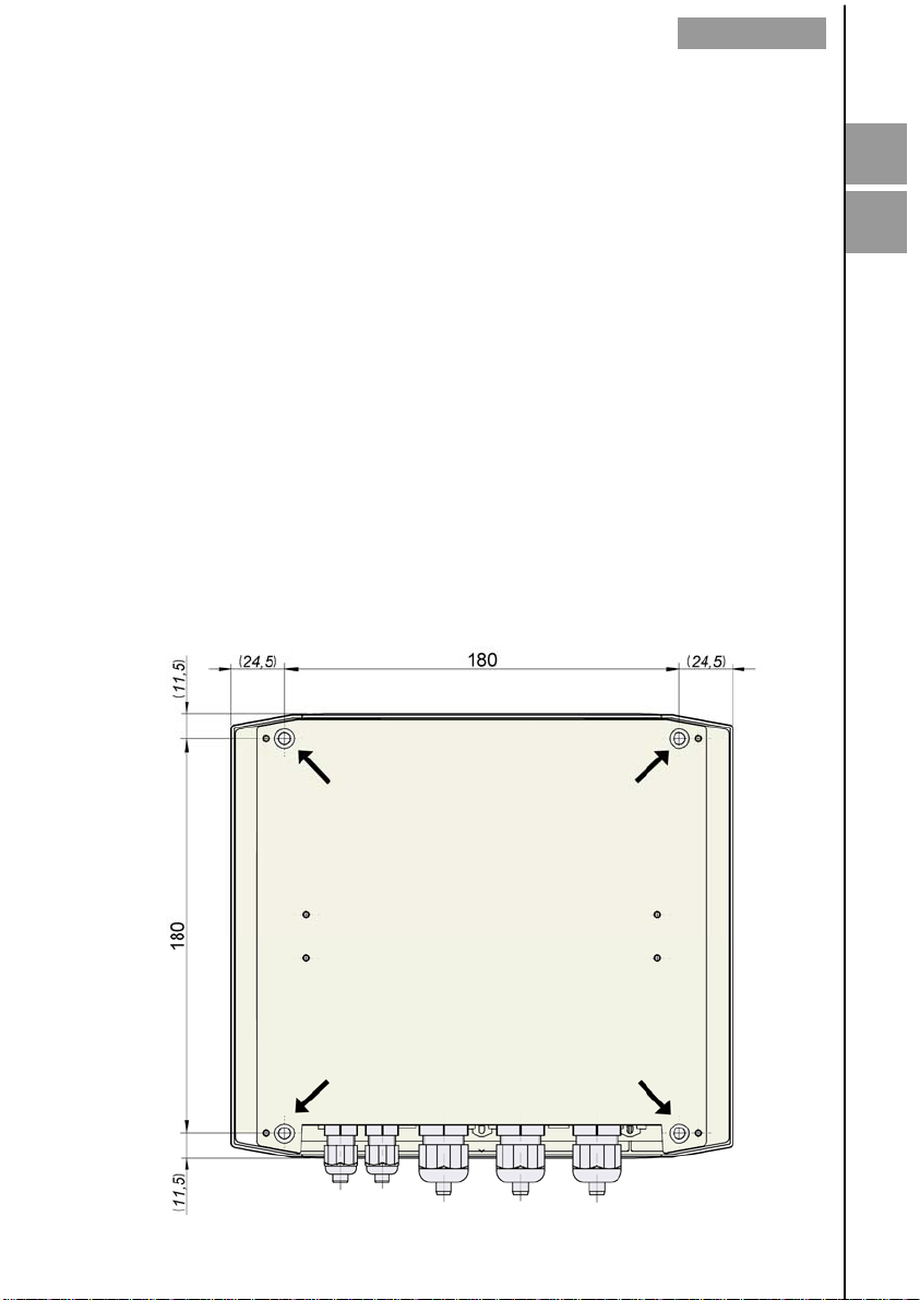
It is recommended to install the electronic converter on a wall near the point where the
flow rate needs to be measured, never on pipes .
To do this, remove the lid and use the 5 mm diameter holes indicated in the figure to fix
the converter to the wall.
1
2
5
Page 6
INSTALLATION OF THE ELECTRONIC CONVERTER
2.1 Electrical connection
For the electrical connection, the CU100 converter has four terminal strips. To help in the
wiring of the equipment, the description of the terminals is marked on the printed circuit
next to each terminal strip.
For the electrical installation it is recommended to use multiple conductor cables with
individual cable sections in the order of 0.25 to 0.5 mm
2
connect. It is better to maintain the cables with mains voltage (power supply) separated
from the cables with low level signals (4-20 mA, etc.).
Before starting the installation, check that the cable glands are the right size for the cables
to be used. This will guarantee the instrument will stay watertight. The cable glands used
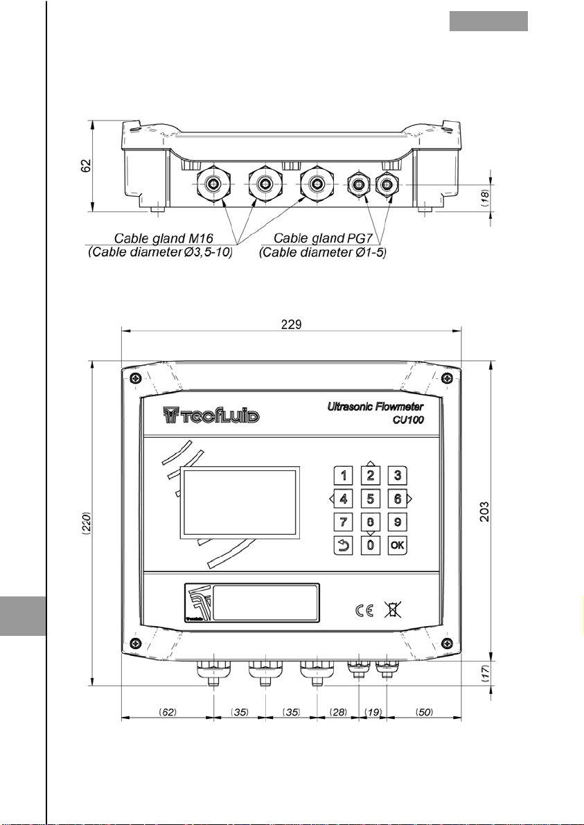
are for cables with outside diameters between 3.5 mm and 10 mm (see page 41 for more
details).
To connect the cables, peel the outside insulation to free the inner cables. It is
recommended to tin the ends of the wires to avoid loose ends. Pass the cables through
the cable glands and screw down in the corresponding positions of the terminal strip.
Once the wiring is finished make sure that the cables are well gripped by the cable glands
to maintain the degree of protection.
Incorrect installation of the cable gland or inadequate cable placement can cause
irreparable damage to the converter.
IMPORTANT NOTE: In order to comply with the electrical safety requirements as per EN61010-1 (IEC 1010-1), the installation of the equipment must take into account the
following:
A mains switch must be provided to disconnect the equipment. This switch must
be marked as the disconnecting device for the equipment and be within easy
reach of the operator.
The mains supply must have an earth line.
The housing must not be opened when the instrument has mains supply
connected.
2
in order to make it easier to
IMPORTANT NOTE: To ensure smooth operation of the equipment, it is recommended to
make the connection paying attention to the following points:
Do not change or modify the junction cable between the transducers and the
converter.
It is recommended to pass the transducer cables through a metallic conduit. The
two cables can go through the same conduit, but never together with other
cables.
For the output signals, use shielded cable when possible.
Keep the cables away from strong sources of noise.
6
Page 7
2.1.1 Power supply wiring
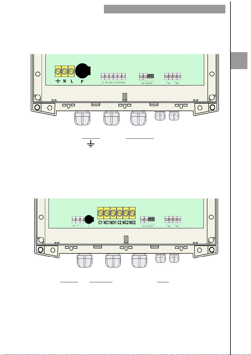
Before starting the installation of the instrument, check that the supply voltage available is
the same as marked on the label of the converter.
Terminal Power supply
Earth
N Neutral
L Phase
It is important to connect the mains earth to the instruments with AC power supply due to
the presence of a mains filter inside that requires this connection.
2.1.2 Relay output wiring
INSTALLATION OF THE ELECTRONIC CONVERTER
2
Terminal Description Relay
C1 Common Relay 1
NC1 Normally Closed Relay 1
NO1 Normally Open Relay 1
C2 Common Relay 2
NC2 Normally Closed Relay 2
NO2 Normally Open Relay 2
7
Page 8
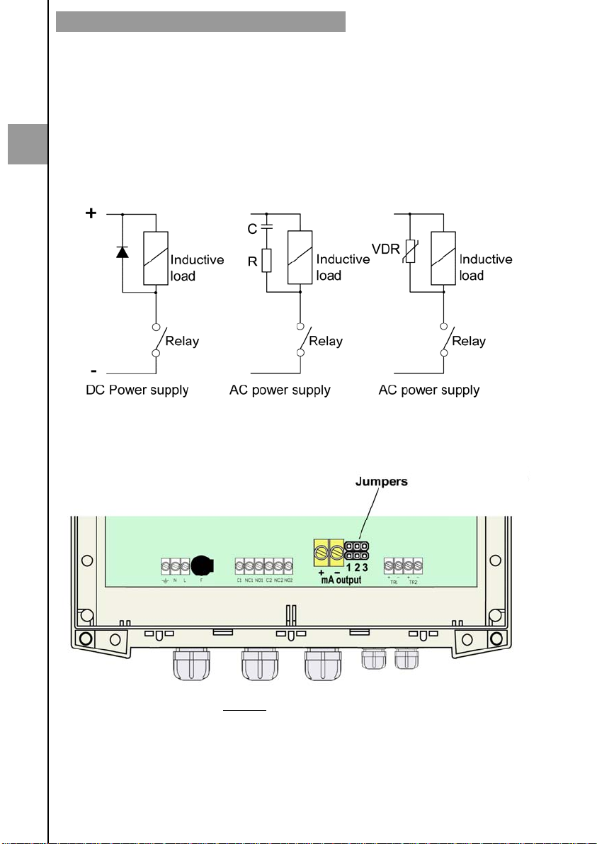
INSTALLATION OF THE ELECTRONIC CONVERTER
The relay outputs are SPDT relays with potential free contacts (see characteristics in
page 40).
The state of the relay contacts corresponds to the relay at rest.
The relay contacts are not protected in any way, and therefore they must be installed
externally as required in the application, taking into account the limitations of the
characteristics of such contacts. In the case of having inductive loads, and to extend the
working life of the contacts of the relays, it is recommended to use overvoltage protection
2
(VDR for AC and diodes for DC loads). In all cases a fuse or some type of short circuit
protection against short circuits, should always be provided according to the needs of the
intended load.
2.1.3 Analog output wiring
Passive mode: pins 2&3
Active mode: pins 1&2
Terminal
+ mA (positive)
- mA (negative)
8
Page 9
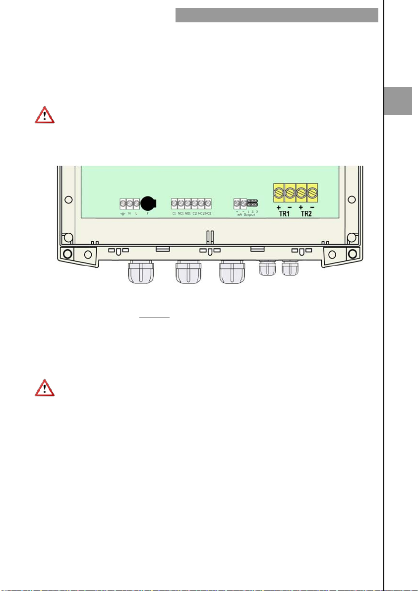
The mA output is galvanically isolated. It can be active (which means that the receiver
device connected to it should have a passive input) or passive (which means that the
receiver device must provide the power supply for the current loop). It is recommended to
use a receptor with an input resistance of less than 700 Ω to guarantee correct operation.
To configure the analog output type (active or passive) there are two jumpers placed just
behind the terminal strip. For the passive mode the jumpers must be situated between
pins 2 and 3 and for active mode the jumpers must be between pins 1 and 2.
NOTE: The analog output has protection against reversed polarity. Due to another
protection against over voltages, if a loop supply voltage of greater than 32 V is connected
the equipment may be damaged.
2.1.4 Transducers wiring
INSTALLATION OF THE ELECTRONIC CONVERTER
2
Terminal
TR1 + Live (positive)
TR1
TR2 + Live (positive)
TR2
The transducers are identified as TR1 and TR2. Be sure to connect the cable TR1 in the
TR1 terminals in the circuit board and the cable TR2 in the TR2 terminals. The exchange
of the transducers can result in a loss of precision of the values measured by the
instrument.
Transducer cables are supplied with plastic indicators 1 and 2 to be connected to the
transducers TR1 and TR2 respectively.
- Shield (negative)
- Shield (negative)
9
Page 10
INSTALLATION OF THE ELECTRONIC CONVERTER
3 CONVERTER INTERFACE
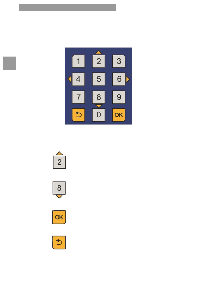
The CU100 converter has a graphic LCD and a keyboard with 12 push buttons.
The keyboard has ten numeric keys to introduce the values of installation and
programming. Two of these keys are used also as cursors, and finally there are two
function keys.
3
The following figure shows the functionality of the converter keys.
To switch between flow rate, totalizer
and fluid velocity screens.
Into the menu, to scroll to the next
higher item.
To switch between flow rate, totalizer
and fluid velocity screens.
Into the menu, to scroll to the next lower
item.
To validate the data.
To enter into installation and
programming modes of the converter.
To exit from an informative text.
To return to the previous menu. To exit
from a screen without validating data.
10
Page 11
4 MAIN MENU
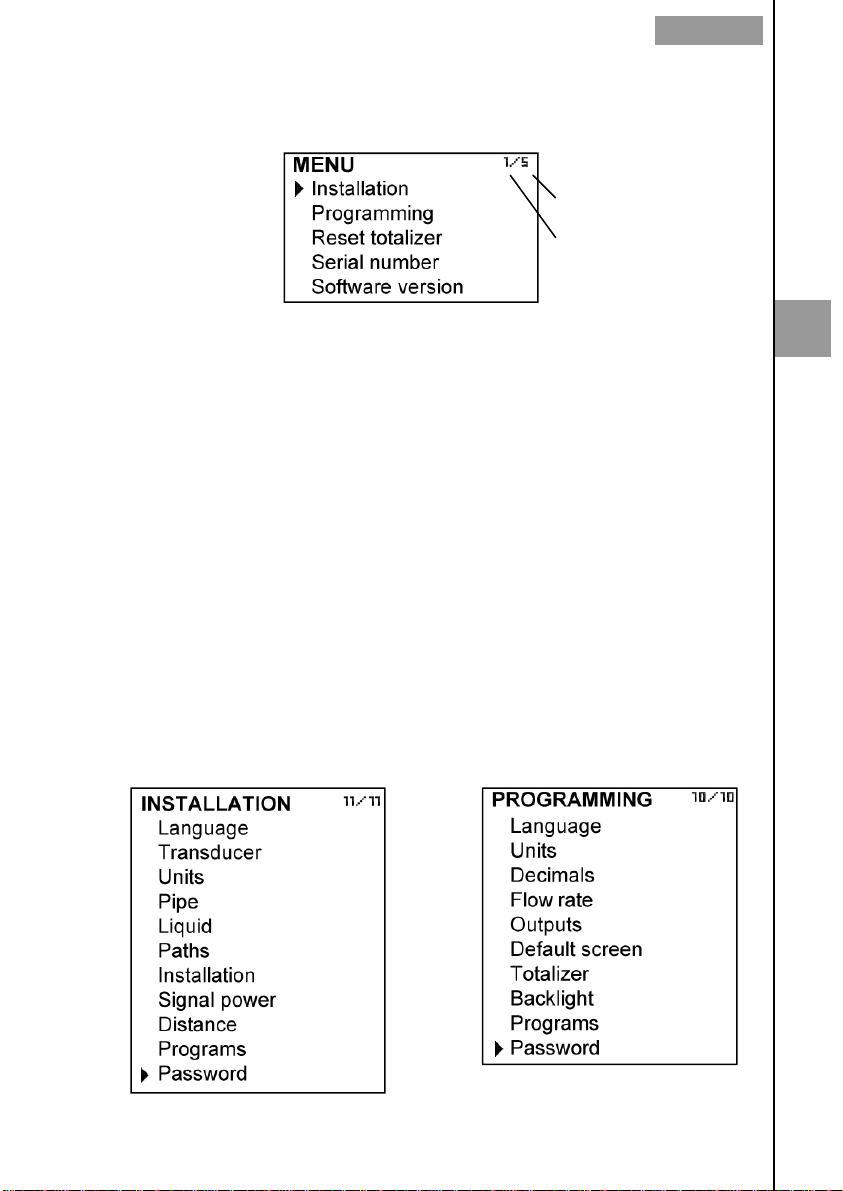
To access the main menu of the converter, press the key (OK). The following screen
appears:
Number of menu items
Selected item
MAIN MENU
The "Installation" option allows the installation of the transducers, as explained in Chapter
5 of this manual.
The "Programming" option allows to program all parameters of the converter, as
explained in Chapter 6 of this manual.
From the "Reset totalizer" option, the user can return the totalizer to zero. When exiting
the menu, the totalizer will begin to accumulate again.
The options "Software Version" and "Serial Number" are informative and are discussed in
Chapters 7 and 8 of this manual.
4.1 Passwords to access the menus
To access the installation and programming menus, a password must be entered. At first
access, the default password is 0123.
The password for the installation menu may be different from the password for the
program menu. If you want to change any of these passwords, you must enter the
corresponding menu and once inside, access the submenu "Password".
To change the access password of
the installation menu, select
"Installation" on the main menu and
then "Password".
To change the access password of
the programming menu, select
"Programming" in the main menu
and then "Password".
4
11
Page 12
4
MAIN MENU
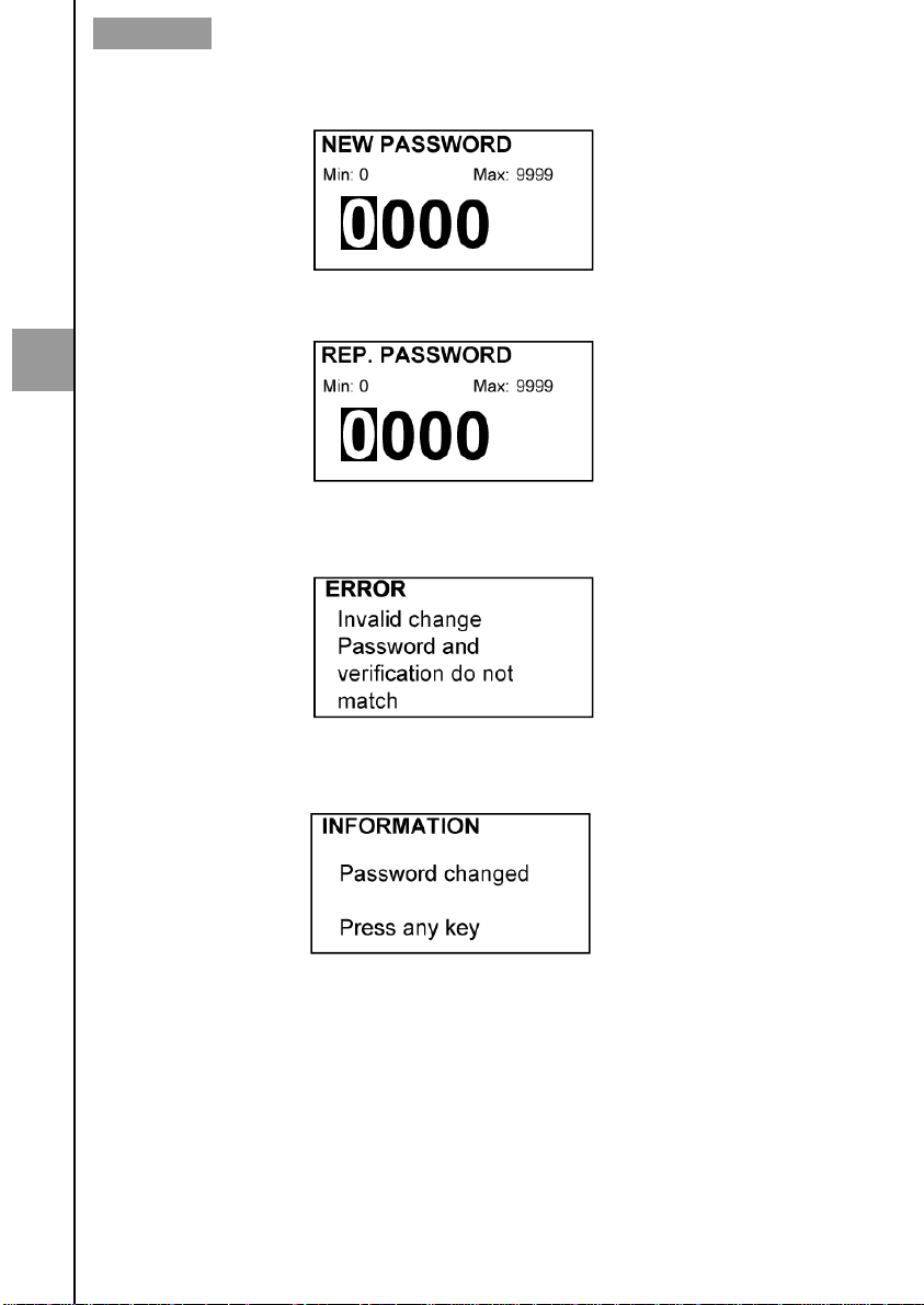
When the "Password" option is selected, a screen to enter the new password appears.
Once entered, the new password is asked again to avoid possible inadvertent error.
If the re-entered password does not match the first one, the following error message
appears and the process should be carried out again.
If both passwords match, the following message is displayed:
12
Page 13
TRANSDUCERS INSTALLATION
5 TRANSDUCERS INSTALLATION
Make sure that the surface of the pipe where the transducers will be installed is clean and
free of oxides or other dirt.
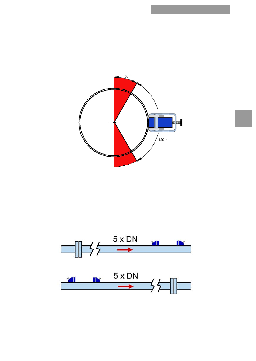
If possible, always install the transducers on a rising pipe, to ensure that it is always full of
liquid.
If the installation of the transducers is in a horizontal section, they should not be placed in
the top of the pipe, but in the area indicated in the figure below:
5.1 Straight pipe run requirement
In order to obtain the maximum reading stability and accuracy, the point where the
transducers will be installed must meet some requirements regarding the straight pipe
sections before and after this point.
If the element that can disturb the flow profile is a fitting such as a flange, the straight pipe
section before and after the transducers should be minimum 5 x DN.
5
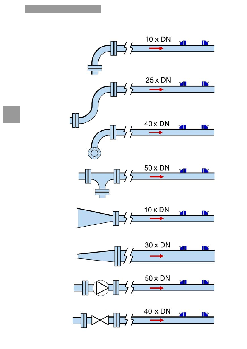
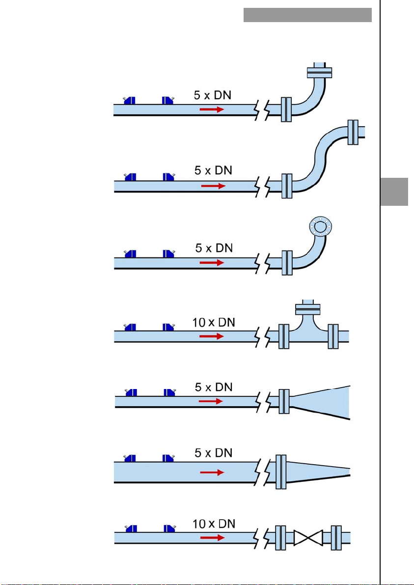
Some plant elements such as pumps, valves, etc., can create turbulences that distort the
flow profile resulting in incorrect measurements. In this case, the distances of straight pipe
without disturbing elements before and after the transducers can be higher, as shown in
the following pages:
13
Page 14
TRANSDUCERS INSTALLATION
element before
the transducers
90º double elbow
5
90º double elbow
in different planes
Disturbing
90º elbow
in one plane
Tee
Minimum distance between the
first transducer and the element
Reducer
Diffuser
Pump
Valve
14
Page 15
TRANSDUCERS INSTALLATION
Disturbing
element after
the transducers
90º Elbow
90º double elbow
in one plane
90º double elbow
in different planes
Minimum distance between the
second transducer and the ele-
5
Tee
Diffuser
Reducer
Valve
15
Page 16
TRANSDUCERS INSTALLATION
5.2 Installation with the alignment guide
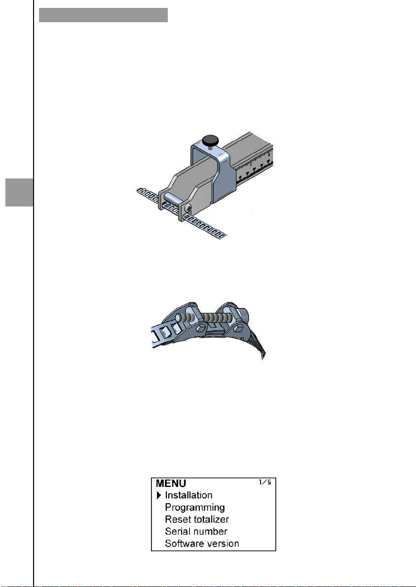
It is convenient to use the alignment guide (normally supplied for pipes from DN80 to
DN350), to guarantee that the transducers are perfectly aligned.
In case that the guide is not required or it is not supplied, the transducers can be installed
directly with the supplied straps (see paragraph 5.12 page 22).
5.2.1 Straps preparation
Pass the free end of the strap through the two slots of one end of the guide.
5
Place the strap encircling the pipe, positioning the free end over the hooks and below the
screw. Snap the hooks on the tightest position possible. Tighten the connection with a
screwdriver until the guide is fixed rigidly, with no possible movement due to vibrations.
Proceed in the same way for the second strap.
5.3 Fastening of the transducers
In order to fix the transducers it is necessary to calculate de optimum separation distance
between them. This distance depends on some parameters of the pipe and the liquid that
flows through it. The calculation of the separation between the transducers needs to enter
the following parameters.
Turn on the electronic converter. It is not necessary that the transducers are installed.
Press the (OK) key in order to enter the main menu.
With the keys (2) and (8), select “Installation”, and then validate with the key (OK).
16
Page 17
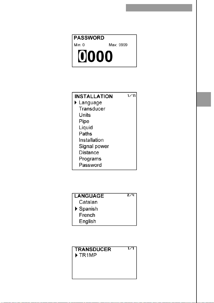
In order to access to the transducers installation menu, a password must be entered. When
accessing the first time, the default password is 0123. For more details about the password,
see paragraph 4.1, page 11.
Once the password is entered, and after pressing the key (OK), the first shown screen
allows to choose between the different options of the installation menu.
5.4 Entering the installation parameters
TRANSDUCERS INSTALLATION
5
5.5 Language
You can choose the language in which all the menus will be seen.
5.6 Transducer
You can choose the transducer model used in the installation.
17
Page 18
TRANSDUCERS INSTALLATION
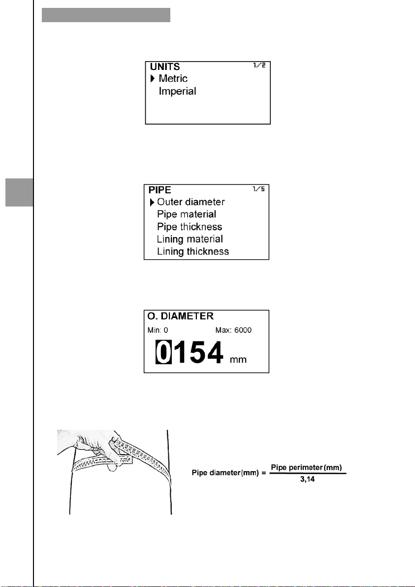
5.7 Units
User can choose between metric and imperial units.
5.8 Pipe parameters
It is necessary to know some data such as materials, thicknesses, etc., so that the
flowmeter can perform the necessary calculations to obtain the flow rate accurately.
5
First, the outer diameter of the pipe must be entered.
5.8.1 Outer diameter
The outer diameter value must always be entered in millimetres.
If this parameter is not known, it can be calculated by measuring the circumference or
perimeter of the pipe.
18
Page 19
5.8.2 Pipe material
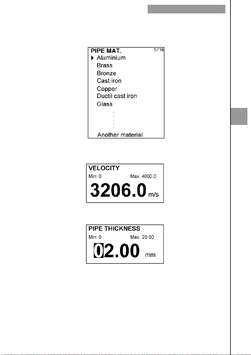
For the programming of the CU100 ultrasonic flowmeter, a list with several common pipe
materials is available. For each material the flowmeter has the necessary data to perform a
good measurement.
In the event that the pipe material is not on the list, you must select “Another material”, in the
last position in the list. In this case, the sound propagation velocity of the material must be
entered.
TRANSDUCERS INSTALLATION
5
5.8.3 Pipe thickness
It is usually indicated on the pipe.
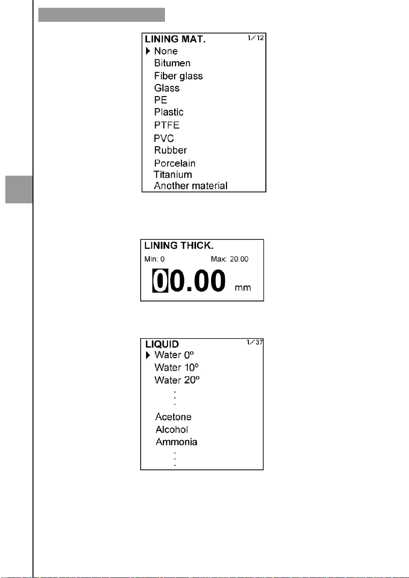
5.8.4 Lining material
If the pipe has an internal lining, in this screen the lining material can be selected. In the
same way as in paragraph 5.8.2, if the material is not in the list, “Another material” must be
selected and the sound propagation velocity of the material must be entered.
In the event that the pipe does not have any internal lining, select “None”.
19
Page 20
TRANSDUCERS INSTALLATION
5
5.8.5 Lining thickness
If the pipe has an internal lining, its thickness should be entered, in the same way as in the
pipe thickness.
5.9 Liquid
The liquid that flows through the pipe should be selected.
If the liquid is not in the list, “Another liquid” must be selected. In this case, it is necessary to
enter the sound propagation velocity of the liquid.
20
Page 21
5.10 Paths
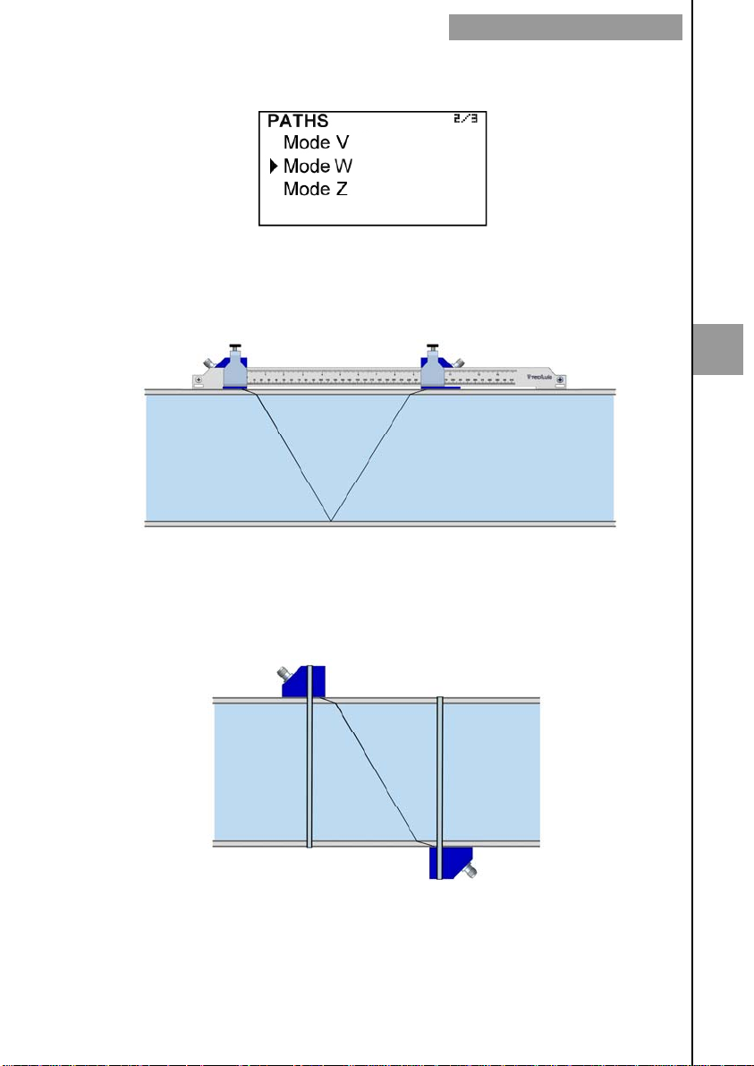
The number of paths is given by the transducer installation method.
For pipe diameters up to 350 mm, V mode is recommended. This mode ensures that the
propagation path of the ultrasonic wave is long enough so that the instrument can
successfully perform the measurement. V mode consists of placing the transducers
aligned on the pipe. The propagated signal is reflected in the central point on the opposite
side of the pipe.
TRANSDUCERS INSTALLATION
5
V mode
For pipe diameters bigger than 350 mm, Z mode is recommended, which consists of
placing the transducers on opposite sides of the pipe. The signal is propagated directly
from one transducer to the other.
Z mode
Depending on the pipe material and the process fluid, the selection of transducer
placement mode (V or Z) according to pipe size may be different than above indicated.
21
Page 22
TRANSDUCERS INSTALLATION
5.11 Installation and distance between the transducers
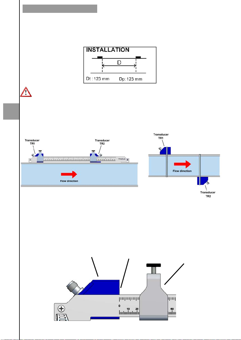
This screen shows the theoretical distance (Dt) at which the transducers should be placed
to work in the best conditions. The practical distance (Dp) is explained in the paragraph
5.14.
To place the transducers it is essential to apply a layer of ultrasound gel at its base. This
gel is supplied with the equipment.
5.12 Fixing the transducers
5
The transducers should be placed so that the liquid flows from TR1 to TR2, in order that
when the liquid flows in the usual direction, the displayed flow rate has a positive sign.
V mode
It is recommended to fix initially only one of the transducers since in general there are
small differences between the theoretical and the optimal distance. The fine adjustment of
the position of the second transducer is done by using the option "Signal Strength" of the
menu (see paragraph 5.13 page 24).
In case the installation is made by means of the alignment guide, it is recommended to
place the transducer TR1 with the gel at the end of the guide so that its inner side
matches the zero point of the ruler.
Transducer
Inner side
22
Z mode
Fastening “U”
Page 23
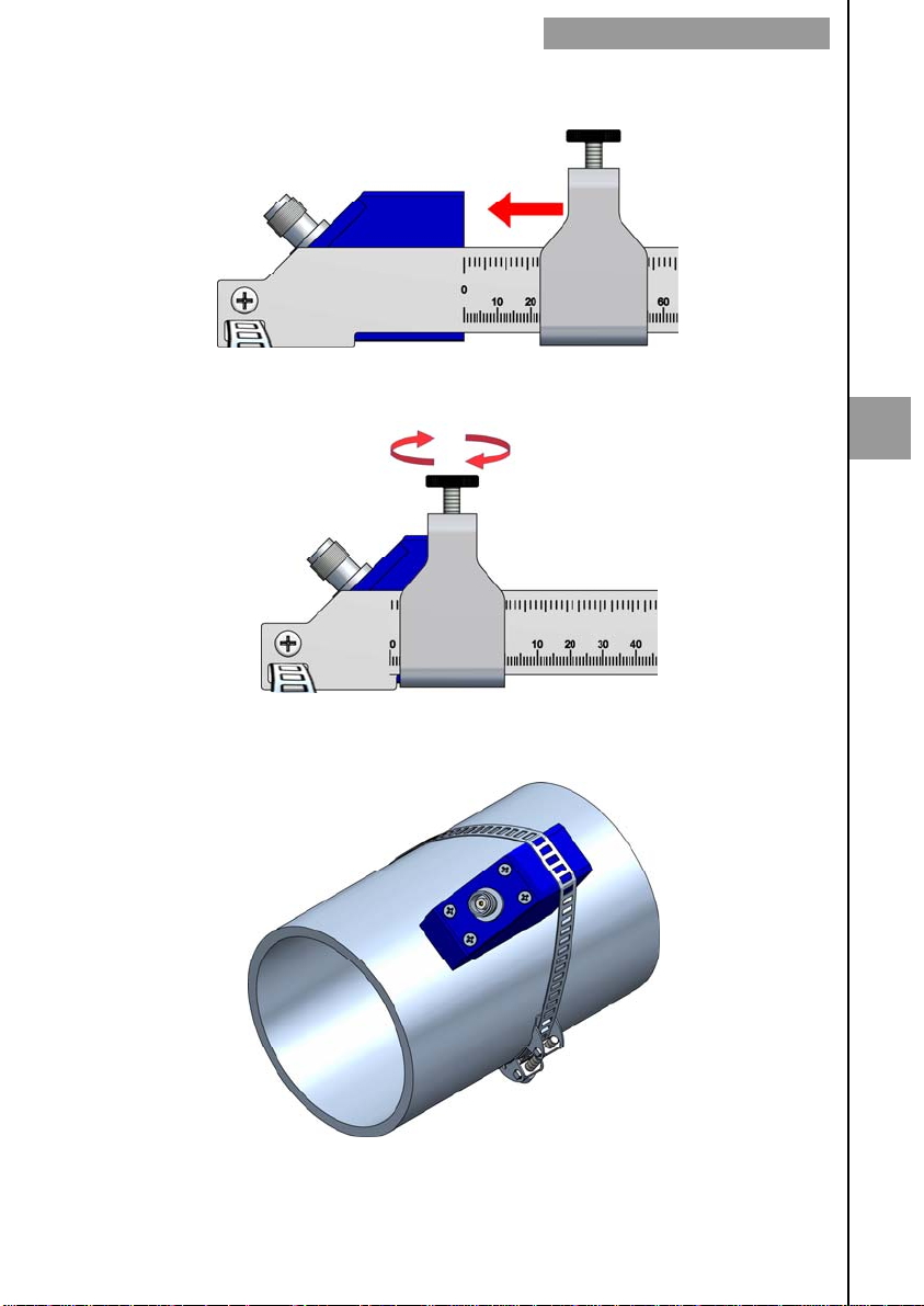
After placing the transducer, move the fastening "U" to it until the knurled screw matches
the transducer top notch.
Once in this position, tighten the screw until the transducer is pressed against the pipe.
TRANSDUCERS INSTALLATION
5
If the alignment guide is not available, place the strap around the pipe and tighten it so
that it holds the transducer.
Place the transducer cables by screwing the connectors, and taking into account that the
cable TR1 must be connected to transducer TR1 and the cable TR2 to the transducer
TR2.
23
Page 24
TRANSDUCERS INSTALLATION
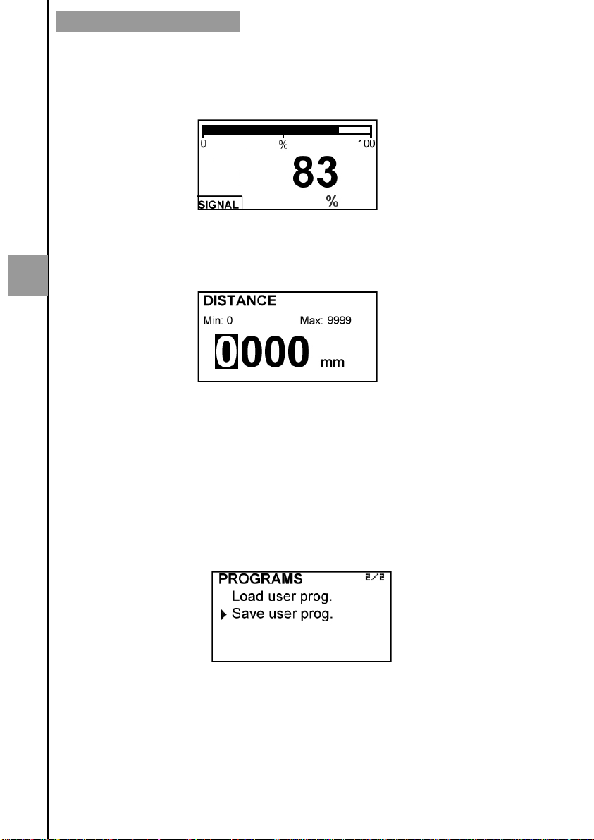
5.13 Signal strength
This screen allows to perform a fine adjustment of the position of the second transducer.
To do so, the second transducer must be moved to find the point where the signal level
indicated on the display is maximum.
Once this point is found, fix the second transducer in the same way as done with the first
one in the paragraph 5.12.
5.14 Distance
5
If the transducers have been placed by means of the fine adjustment of signal strength
(paragraph 5.13), it is necessary to enter the practical distance at which the transducers
have been placed. This distance will be shown on the installation screen (see paragraph
5.11) as Dp.
If the fine adjustment has not been done it is not necessary to go into this screen. Simply
fix the second transducer as indicated in paragraph 5.12.
Once this step is done, exit the installation menu by pressing (Return) to go to operation
screen.
5.15 Programs
It allows to save a device programming, and retrieve it.
If at any time you want all the transducer installation data to be stored in memory as
backup, it can be done by selecting "Save user prog. ".
To restore these data, just select "Load user prog. ".
24
Page 25
CONVERTER PROGRAMMING
6 CONVERTER PROGRAMMING
By programming the converter the visualization and the outputs of the instrument can be
configured.
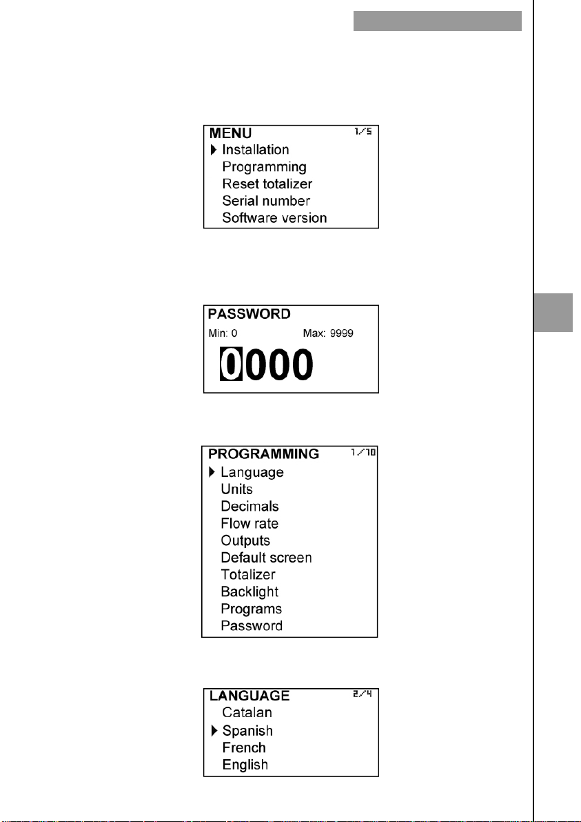
Turn on the converter and press (OK) to enter the main menu. The following screen
appears.
With the keys (2) and (8), select Programming, and then validate with the key (OK).
To access the programming of the converter, you must enter the password. At first
access, the default password is 0123. For more details about the password, see
paragraph 4.1, page 11.
Once the password is entered, the first screen allows to choose between the different
programming options.
6
6.1 Language
You can choose the language in which all the menus will be displayed.
25
Page 26
CONVERTER PROGRAMMING
6.2 Units
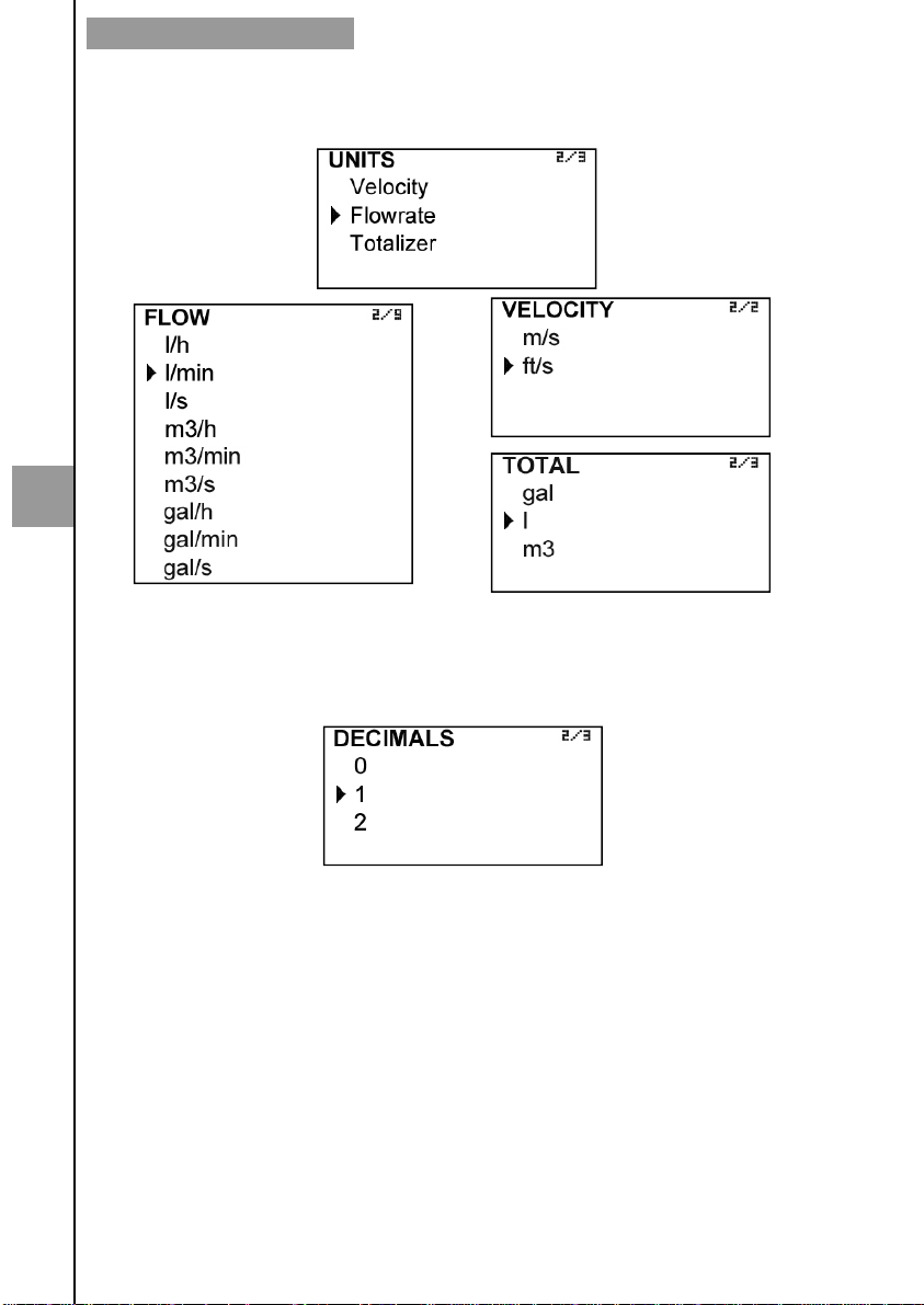
In this screen the units for the liquid velocity, the flow rate and the totalizer can be chosen
independently.
6
Note: Unit gal refers to US gallons.
6.3 Decimals
In this screen the number of decimals for the flow rate indication can be selected.
To select the number of decimals it must be taken into account that the instrument has 5
digits for flow rate indication. If two decimals have been selected, these will be seen whilst
the flow rate is not higher than 999.99. Above this value the indication will automatically
change to one decimal, and when the flow rate is higher than 9999.9 the indication will be
done without decimals.
If one decimal is selected, the flow rate indication will have a maximum of one decimal.
If indication without decimals is selected, the flow rate will always be shown without
decimals.
For the selection of the flow rate units and the number of decimals it must be taken into
account that an indication with an excess of decimals may give the sensation of instability
of the reading. As a general rule it can be considered that the reading should not have
more than a total of 5 digits (integer + decimals).
26
Page 27
6.4 Flow rate
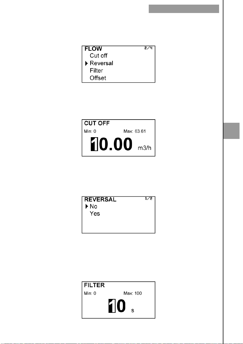
This screen displays a submenu to modify different aspects related to flow reading, such
as cut off, flow reversal, filtering and offset.
6.4.1 Cut off
A cut off flow rate can be programmed, that means, the flow rate below which the flow
rate indication will be zero. This can avoid reading errors in the lower zone of the scale.
The maximum allowed value for the cut off is the equivalent to a liquid velocity of 1 m/s.
6.4.2 Reverse flow rate
The CU100 is a bi-directional flowmeter. The flow rate changes its sign automatically
when the flow is reversed. If after the flowmeter has been installed it is necessary to
reverse the flow rate sign, in this screen it can be done selecting the option “REVERSAL–
Yes”.
CONVERTER PROGRAMMING
6
6.4.3 Damping
The CU100 flowmeter has an adaptive filter (damping) to provide stable flow rate and
analog output readings in the presence of continuous flow rate fluctuations.
The configuration of this filter can be very useful in the cases where the flow rate readings
have some instability (due to air bubbles, solids in suspension, etc…).
27
Page 28
6
CONVERTER PROGRAMMING
Only the flow rate indication of the display and the analog output are affected by the filter.
The relay output and the totalizer act according to the instant flow rate. Selecting a filter
with a longer or shorter integration time will provide more or less stable readings and will
also affect the response time to small variations of flow rate.
The integration time is selected in seconds, with a minimum value of 0 and a maximum
value of 100 seconds. For example, with an integration time of 15 seconds, the display
will indicate the flow rate reading of the average flow rate over the last 15 seconds from the
last update of the display. This does not mean that the display is refreshing its data every
15 seconds. The display shows a new value several times per second, indicating an
average of the flow rate values of the last 15 seconds.
When there is a sudden variation of the flow rate then the filter should react as fast as
possible to give a correct reading of the new value. For this, the filter controls the deviation
of the instant flow rate with respect to a reference for each reading. If this deviation
exceeds the established limits, the filter will stop acting, indicating the instant value, and
will start again the filtering process.
6.4.4 Offset
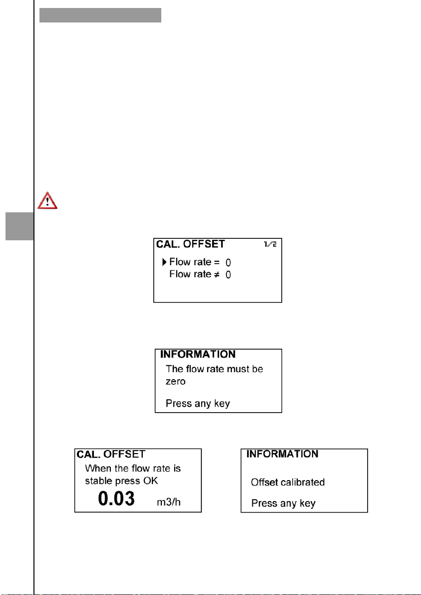
In order to obtain a perfect linearization of the instrument, it is recommended to make an
adjustment of the zero offset each time an installation is performed.
When the option Offset is selected, the following screen is shown:
If the first option to make the correction is chosen, the flow rate must be zero, that is, the
liquid inside the pipe where the transducers are installed should be completely stopped.
When the read flow rate is stable, press the key OK and the instrument will save the
value.
If in the installation is not possible to stop the flow rate, an offset adjustment can be done
if the flow rate is stable.
To do this, press the option “Flow rate ≠ 0 and the following screen will be shown:
28
Page 29
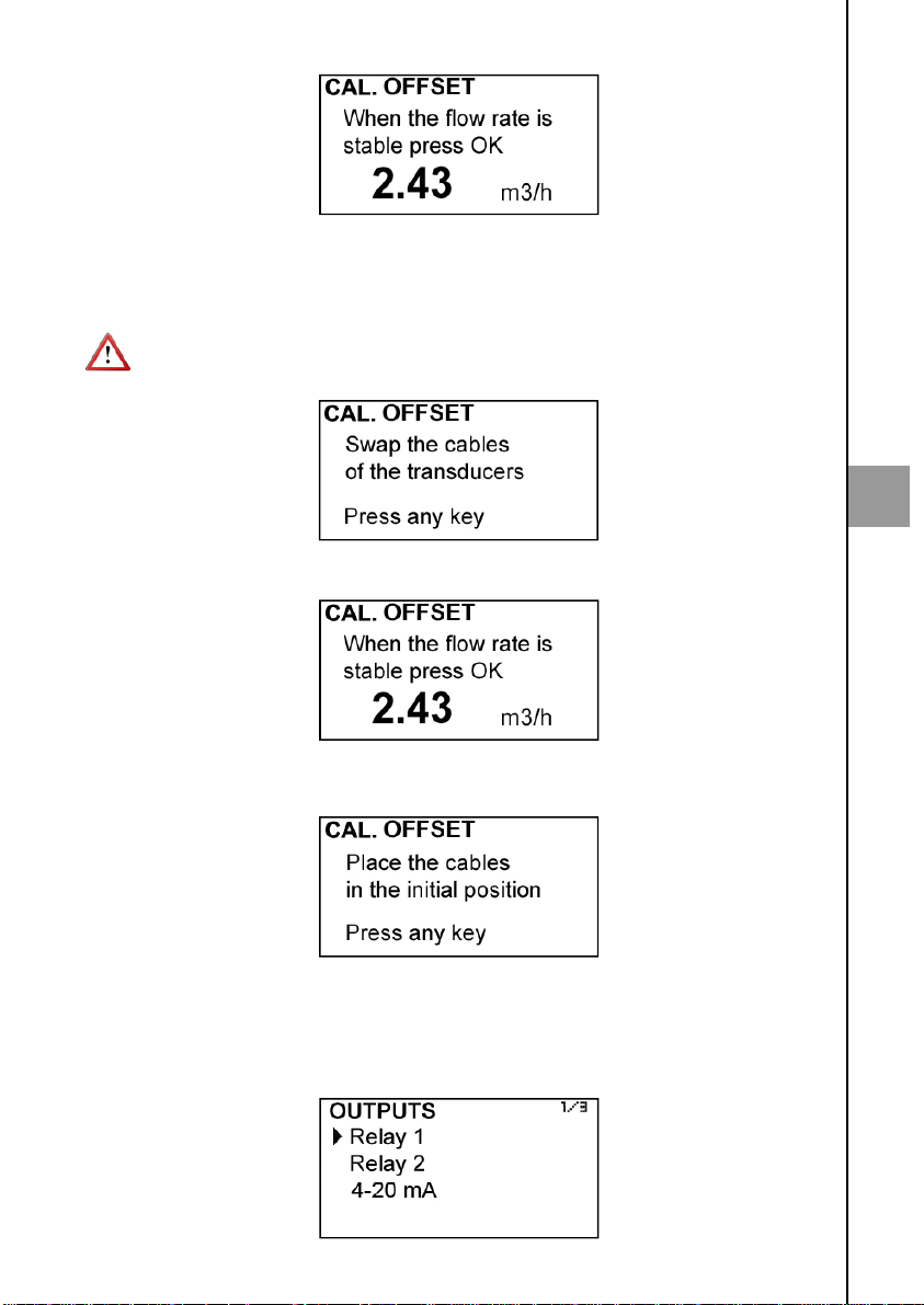
When the read flow rate is stable, press the key OK and the instrument will save the
value.
The following step is to swap the cables of the transducers: the cable TR1 for the
transducer TR1 has to be connected to the transducer TR2 and vice versa.
Do not move the transducers from its position. Only unscrew the two connectors and
swap the cables as described.
Once a key is pressed, the following screen is shown:
6
After pressing OK, the cables must be placed in its original position (cable TR1 to
transducer TR1 and cable TR2 to transducer TR2).
Once a key is pressed, the offset will be adjusted.
6.5 Outputs
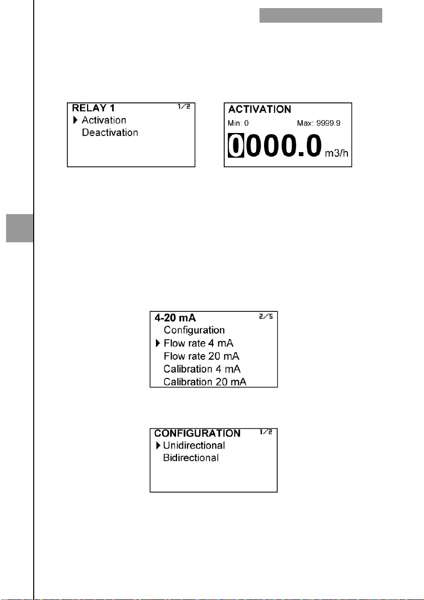
This screen allows to program the three outputs of the instrument: Relay 1, Relay 2 and
analog output (4-20 mA).
29
Page 30
6.5.1 Relay 1 and relay 2
When selecting one of these screens we have access to program the flow rate at which
the relays will change its state and to the level of hysteresis. By level of hysteresis we
understand the difference between connection and disconnection of the output. To avoid
that an alarm output is continuously moving from activate to deactivate state, we must
program the points of connection and disconnection.
Example
If the activation point is programmed to 100 m3/h and the deactivation point is
programmed to 90 m3/h, when the flow rate is zero the output will be off. When the flow
rate reaches a value of 100 m3/h the output will go on and it will not go off until the level
falls below 90 m3/h.
6
If we program an activation point of 90 m3/h and a deactivation point of 100 m3/h, when
the level is zero the output will be on. When the flow rate reaches a value of 100 m3/h the
output will go off and it will not go on until the flow rate falls below 90 m3/h.
6.5.2 Analog output
The flow rate corresponding to 4 mA and 20 mA, and the calibration for these two values
can be programmed.
CONVERTER PROGRAMMING
6.5.3 Configuration
It allows to choose between unidirectional and bidirectional.
If “Unidirectional” is chosen, the analog output will have a value proportional to the flow
rate when positive, and it will provide always 4 mA when negative.
If “Bidirectional” is chosen, the analog output will have a value proportional to the flow rate
whether it is positive or negative.
30
Page 31
CONVERTER PROGRAMMING
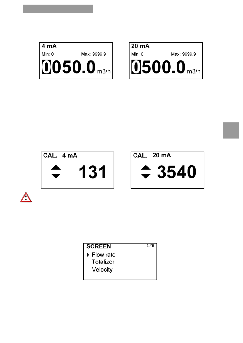
6.5.4 Programming of the 4-20 mA output
Flow rate values equivalent to each current are entered directly.
Programming a flow rate value for 20 mA higher than the one for 4 mA, the loop current
changes from 4 to 20 mA as the flow increases.
Otherwise, programming a flow rate value for 20 mA lower than the one for 4 mA, the
current loop will change from 20 to 4 mA as the flow increases.
6.5.5 Current calibration for 4 and 20 mA
The converter CU100 is delivered with the current output already calibrated. If you want to
correct a derive of the 4 or 20 mA current values because they don’t coincide with the
ammeter used, it can be done by pressing the keys (2) and (8) to increase or decrease
the current respectively in each case. The values shown on the screen are reference
levels. When one of this data is confirmed, the CU100 will take the current value shown
on the ammeter as a reference.
6
Before doing a current calibration, be sure that the ammeter used for that is showing the
real measure.
6.6 Default screen
Flow rate, totalizer or liquid velocity screens can be programmed as a default. Thus, the
converter presents this screen when a power failure occurs or when returning from the
installation or programming menu.
6.7 Totalizer
In this screen you can configure the totalizer operation mode depending on the flow
direction. Thus, the value indicated by the totalizer will always be true regardless of the
application where the instrument is installed.
31
Page 32
6
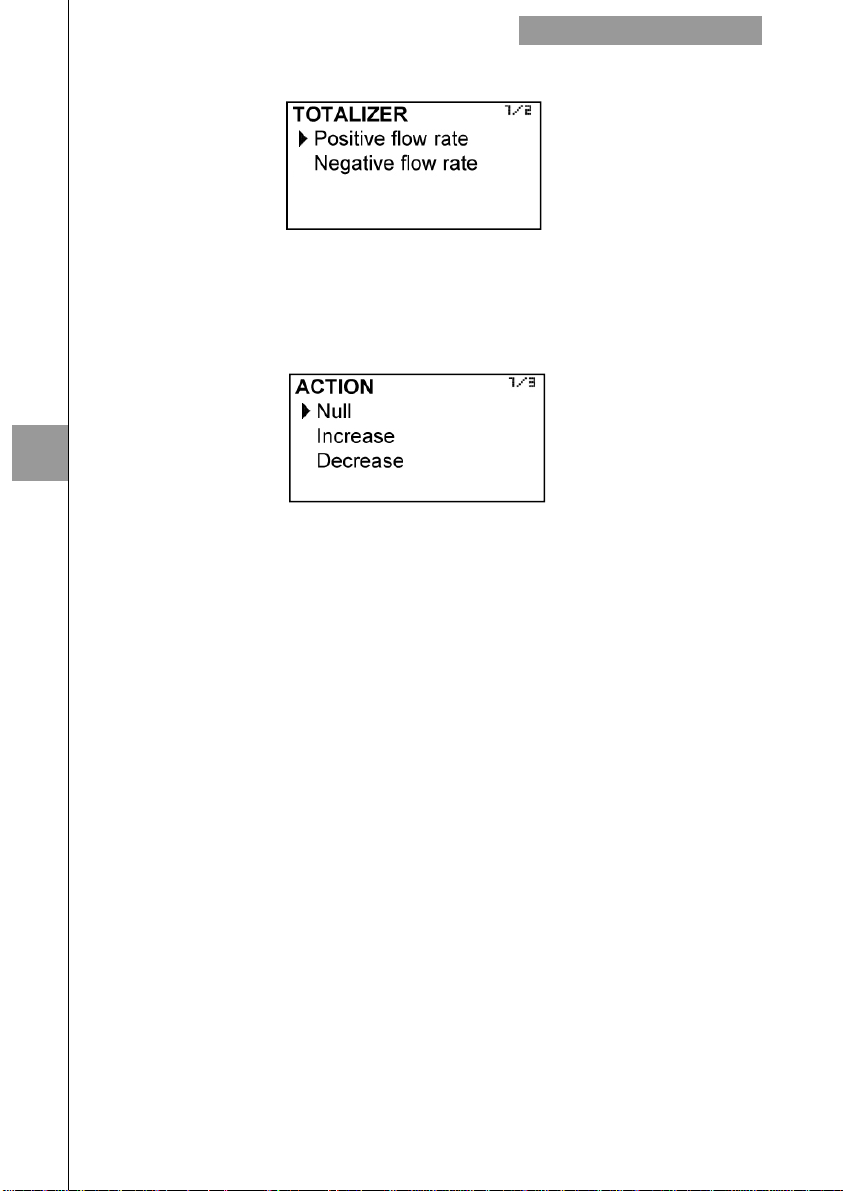
The first screen after selecting “Totalizer” is the following:
In this screen you can choose the flow direction for which you want to configure the action
that the totalizer will do.
Positive flow is defined as the one that appears unsigned on the default screen, and
negative flow the one that appears with a — sign on the default screen.
Once the flow rate direction is chosen, a screen with the different actions is shown:
If "Null" is selected, the totalizer remains unchanged. If "Increase" is selected, the totalizer
will add the amount of fluid passing through the flowmeter, and if you select "Decrease",
the totalizer will subtract that amount.
Examples:
a) Installation in which for a time the product flows through the pipe and after that a
cleaning process in reverse is performed. The programming will be:
Positive flow rate action: Increase
Negative flow rate action: Null
b) Installation in which for a time the product flows through the pipe to a tank, and
after that a quantity of the product comes back in the opposite direction. The
programming will be:
Positive flow rate action: Increase
Negative flow rate action: Decrease
The totalizer will indicate the volume of product that there is in the tank.
b) Installation in which for a time a first product flows through the pipe, and after that
a second product flows in the opposite direction. The programming will be:
Positive flow rate action: Increase
Negative flow rate action: Increase
The totalizer will indicate the volume corresponding to the sum of the two
products.
CONVERTER PROGRAMMING
32
Page 33
CONVERTER PROGRAMMING
6.8 Backlight
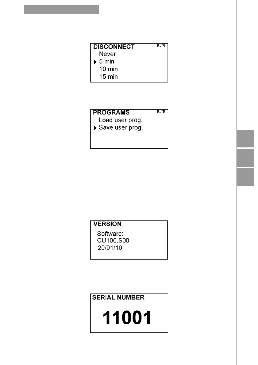
This screen allows to select how long it will takes the backlight to turn off from the moment
you release a key.
6.9 Programs
It allows to save the device programming, retrieve it or load a default configuration.
6
If at any time you want all the transducer installation data to be stored in memory as
backup, it can be done by selecting "Save user prog.".
To restore these data, just select "Load user prog. ".
7 SOFTWARE VERSION
From the main menu, if “Software version” is selected, the screen will show this data and
the corresponding date.
8 SERIAL NUMBER
In this section the converter serial number is shown.
7
8
33
Page 34
9 DEFAULT SCREEN
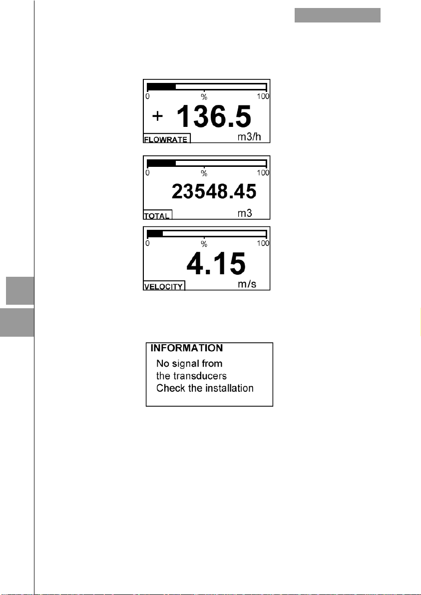
When exiting the menu, the display shows the default screen. To scroll between the three
operating screens, press the key (2) or (8).
DEFAULT SCREEN
9
10
If the device detects no signal at the transducers, because the attenuation is very high, or
due to a bad connection or broken cable, the operating display appears as an informative
screen indicating this situation
10 MAINTENANCE
No special maintenance is required .
For cleaning, a humid cloth can be used, and if necessary with a little neutral soap.
Solvents or other aggressive liquids which could damage the housing material should not
be used.
10.1 Fuse
In the event that the fuse blows, this should be replaced with a slow blow “T” fuse, size
Ø5 x 20 mm and value 250 mA.
.
34
Page 35
ASSOCIATED SOFTWARE WINSMETER CU
ASSOCIATED SOFTWARE WINSMETER CU
11
Most of the steps in the preceding paragraphs can be done by means of the device
associated software Winsmeter CU, which allows working in a more comfortable and
intuitive way.
Such software can be downloaded from the following link of the Tecfluid S.A. website.
www.tecfluid.com/downloads/winsmeterCU.zip.
11.1 USB cable connection and drivers installation
Extract the files from the winsmeterCU.zip to a new system folder.
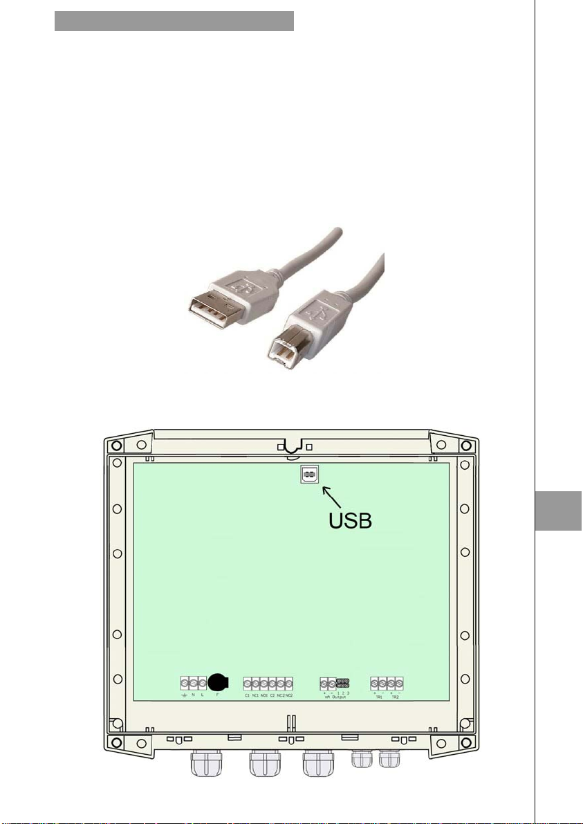
In order to connect the converter to a computer an USB cable is required. This cable is type
A at one end and type B at the other, and it is readily available on the market.
In the picture you can see the ends of the cables.
The first step to do the connection is to open the lid of the electronic converter.
35
11
Page 36
To open the lid, remove the four screws. The USB connector is located on the opposite side
of the cable entry glands.
Connect the USB cable at one end to the converter and at the other to the computer where
the software is installed.
Turn on the electronic converter.
Windows XP:
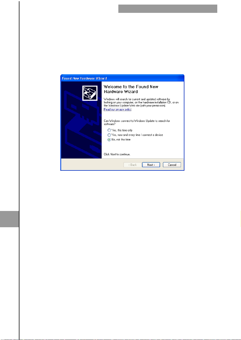
“Found New Hardware Wizard” appears, with the following question:
Can Windows connect to Windows Update to search for software?
ASSOCIATED SOFTWARE WINSMETER CU
11
If you have Internet access, answer “Yes, this time only”.
If you do not have Internet access, answer “No, not this time”.
If you answered “yes”, drivers will be installed automatically. Otherwise, finish the wizard
and then run the file "Drivers_Winsmeter_Setup.exe". The will guide you until the drivers
are installed.
Windows 7
If you have Internet access, a message reporting that the drivers have been installed will
appear.
If you do not have Internet access, a message reporting that the drivers can not be
installed will appear. In this case, run the file "Drivers_Winsmeter_Setup.exe". The
program will guide you through the installation process until the drivers are installed.
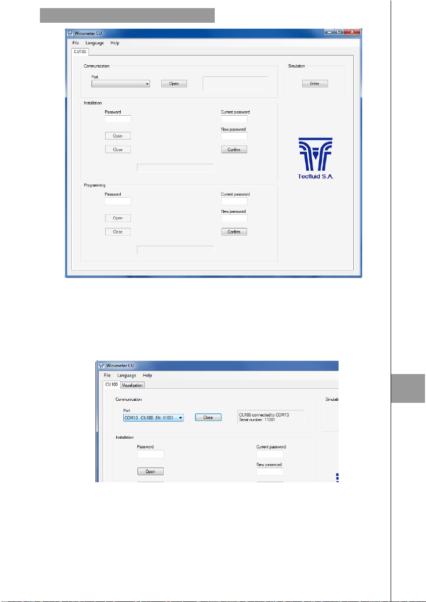
Once the computer has the drivers installed, run the WinsmeterCU.exe. The following
screen appears.
36
Page 37
ASSOCIATED SOFTWARE WINSMETER CU
11.2 Port connection
In the "Port" section, choose the appropriate port for the converter. This will appear with the
name of the port followed by CU100 and its serial number. Then click "Open".
Once the port is open, the button "Open" in the "Installation" section activates.
11.3 Access to installation and programming
In order to access the tab "Install", you must enter a password.
The default password is install, and it can be changed using the boxes on the right of the
"Installation" section.
Likewise, to access the tab "Programming" it is necessary to enter the password which by
default is program. This can be changed using the boxes on the right of the "Programming"
section.
37
11
Page 38
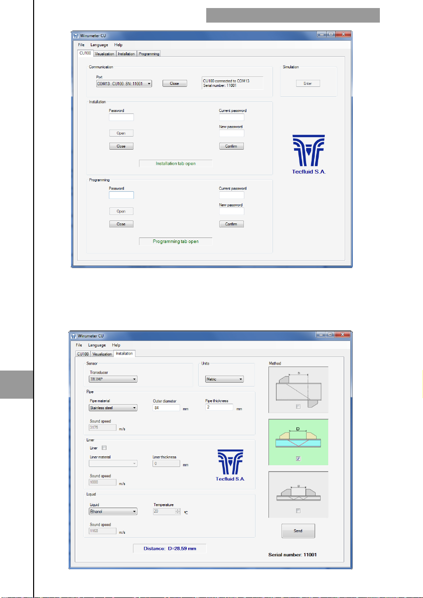
Once the password is written, press "Enter" or the corresponding "Open", and the installation
or programming tab will open as appropriate. At the bottom of each section displays
"Installation tab open" or "Programming tab open."
To enter the Installation window, just click the appropriate tab.
ASSOCIATED SOFTWARE WINSMETER CU
11
38
Page 39
ASSOCIATED SOFTWARE WINSMETER CU
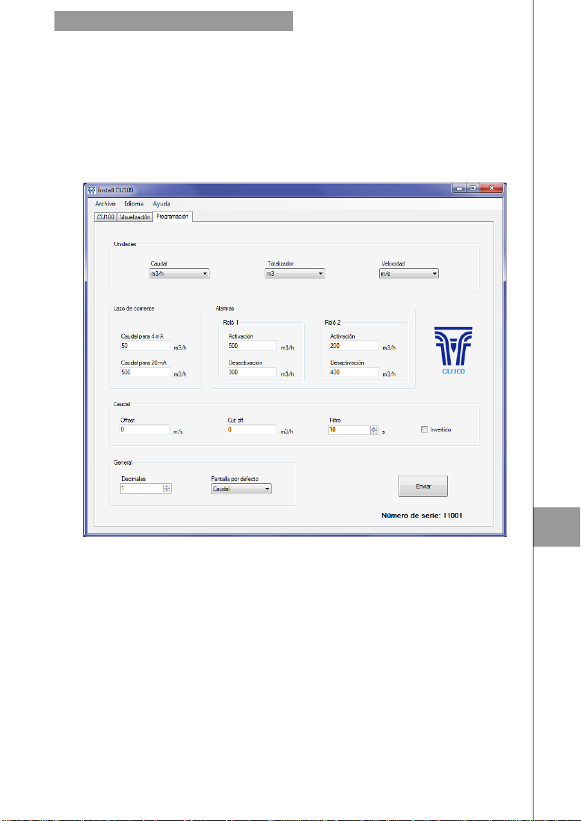
Changing settings on this screen, you get the distance between the transducers on the
bottom.
To transfer data to the CU100 converter, press the “Send” button. The message "Saving
program" will appear for two seconds in the converter screen. The installation data will be
stored in the memory of the converter.
Likewise, to enter into the programming window, just click the appropriate tab.
Changing the parameters of this screen, you can program the different functions of the
equipment.
As in the previous paragraph, to pass data to the CU100 converter, press the “Send” button.
The message "Saving program" will appear for two seconds in the converter screen. The
programming data will be stored in the memory of the converter.
11.4 Visualization
When the communication with the computer port is established (see section 11.2), the tab
"Visualization" opens. This tab lets you view real-time flow rate, totalizer and velocity values,
as well as the current value of the analog output and the state of the relay outputs.
39
11
Page 40
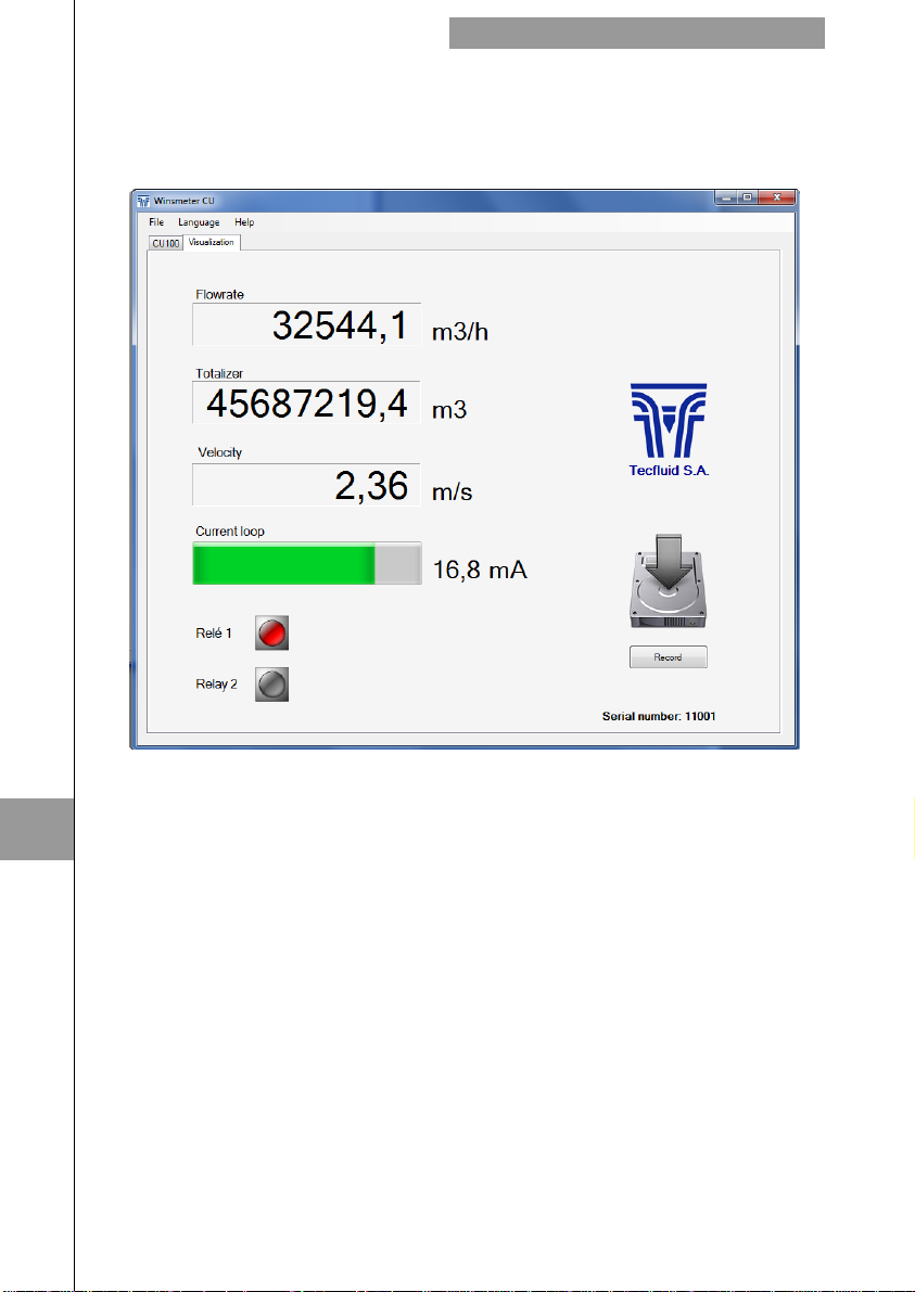
It is an intuitive tool to verify that the instrument has been installed and programmed
correctly.
By means of the "Record" button, you can store data in different computer files, which can
then be processed by other software.
ASSOCIATED SOFTWARE WINSMETER CU
11
11.5 Simulation
If the converter CU100 is not available, the software can be used in simulation mode.
To do this, press the button "Enter" in the simulation section on the initial screen (see figure
on page 36).
Tabs "Installation" and "Programming" will open.
You will be able to calculate the distance between the transducers and change the data,
although they may not be sent to the converter.
40
Page 41
TECHNICAL CHARACTERISTICS
TECHNICAL CHARACTERISTICS
12
Accuracy
± 1,5% of reading ± 0,02 m/s
Repeatability
± 0,25% of reading ± 0,01 m/s
Velocity range
0,2 ...12 m/s
Temperature
Process temperature: -20 ºC … 80 ºC
Ambient temperature range: -20 ... +60 ºC
Power supply
85 ... 265 VAC 50, 60 Hz .
Power consumption: ≤ 5 VA
Analog output
4-20 mA. Active or passive. galvanically isolated from the power supply.
Relay outputs
Two changeover contacts, SPDT, potential free
Contact characteristics:
Maximum voltage : 250 VAC
Maximum current : 8 A
Maximum power : 500 VA
Totalizer
N. of digits: 8 (2 decimals)**
Digit size: 8 mm
Reset: by means of keyboard
Flow rate and velocity indication
Nº of digits: 5 (up to 2 decimals configurable)**
Digit size: 11 mm
** When the available digits are full and the integers overflow a decimal is automatically
lost.
General characteristics
Materials:
Transducers : Anodized aluminium and PEEK
Housing : ABS
Ingress protection (transducers and housing): IP65
Maximum transducer cable length: 50 m
12
Conforms to Low voltage Directive 2006/95/EC
Conforms to Electromagnetic compatibility Directive 2004/108/EC
41
Page 42
DIMENSIONS
13
DIMENSIONS
13
42
Page 43
DIMENSIONS
43
13
Page 44
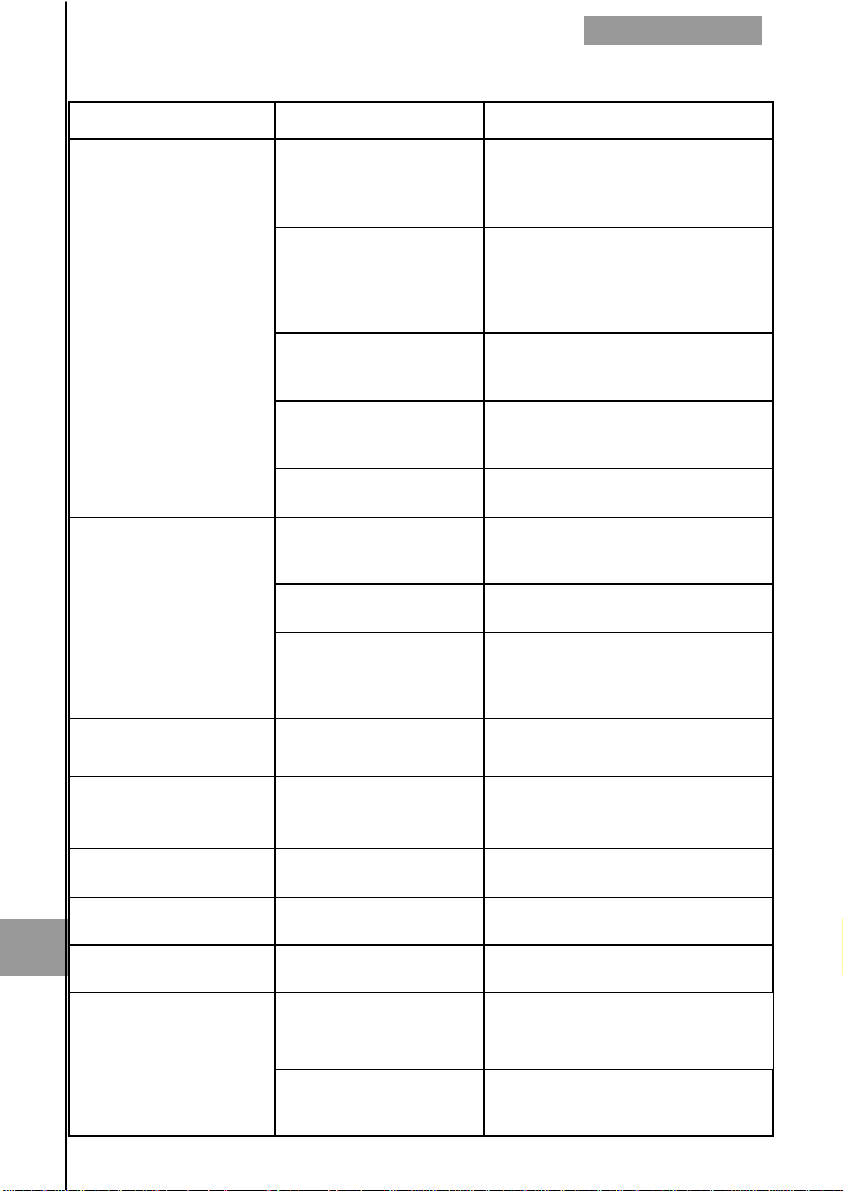
TROUBLESHOOTING
14
Problem Probable cause Solution
TROUBLESHOOTING
14
The pipe is not completely
full.
The transducers are not at
The display shows an error
informative message
instead of the default
screen
The flow rate is unstable
The instrument displays a
value when there is not
flow
The displayed flow rate is
higher than expected
Display is blank Blown fuse.
The analog output
provides always 4 mA or
The analog output gives
always 0 mA
the correct distance.
There is not gel in the
transducers.
The pipe surface is not
adequate.
Cables are broken or
disconnected.
The product contains solid
particles in suspension.
The product contains air.
There are excessive
turbulences.
The offset is not adjusted.
The pipe is not completely
full.
Current output range not
properly programmed.
Cable disconnected. Check the cable connection.
Make sure that the pipe is completely
full, for example, installing the
flowmeter in a vertical pipe with
upwards flow.
Enter the installation menu and verify
that all parameters are correct. Check
that the transducers are at the
theoretical distance.
Put acoustic adaptation gel on the
base of each transducer.
Dirty or rusty surfaces can difficult the
transmission of ultrasonic waves.
Clean the pipe.
Check the cables between the
converter and the transducers.
Verify that the flowmeter is suitable for
this application.
Verify that the flowmeter is suitable for
this application.
Verify that the transducer installation
has been made according to the
recommended straight pipe
requeriments (paragraph 5.1 page13).
Perform an offset adjustment
(paragraph 6.4.4 page 28).
Make sure that the pipe is completely
full, installing the flowmeter in a in a
vertical pipe with upwards flow.
Change the fuse.(paragraph 10.1
page 33).
Program the range properly
(paragraph 6.5.4 page 30).
The totalizer does not
change its value
The flow rate is negative
(with respect to the fluid
direction).
The totalizer action is
programmed to do it.
44
Program the positive flow rate
direction according to the flow
direction (paragraph 6.4.2 page 27).
Change the totalizer programming
(paragraph 6.7 page 30).
Page 45
ANNEX A
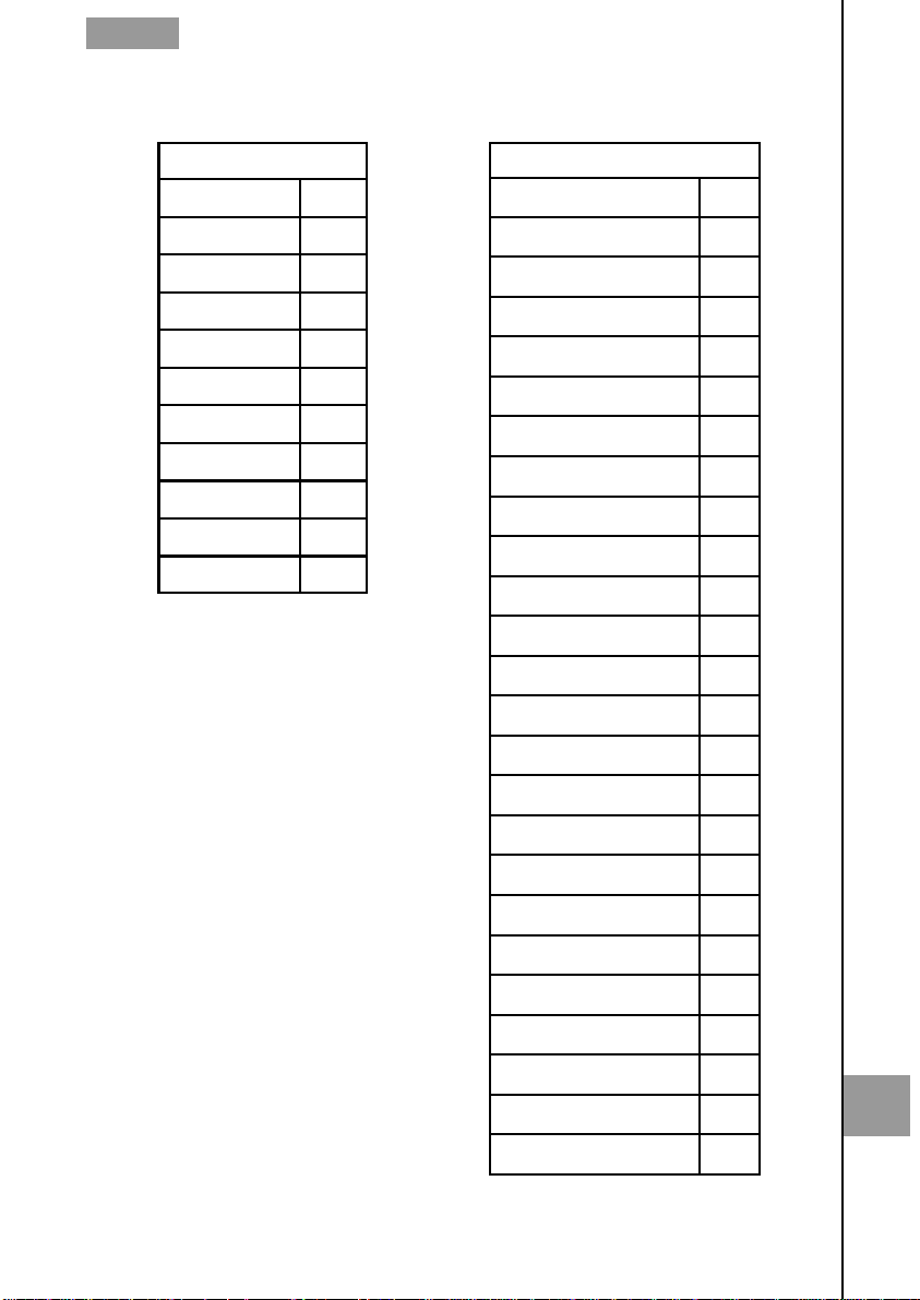
Annex A. Sound propagation velocity in some liquids (in m/s).
Water
0 ºC 1403
10 ºC 1447
20 ºC 1482
30 ºC 1507
40 ºC 1526
50 ºC 1541
60 ºC 1552
70 ºC 1555
80 ºC 1555
90 ºC 1550
100 ºC 1543
Liquids
Acetone 1190
Alcohol 1207
Ammonia 1386
Aniline 1649
Beer 1482
Benzene 1320
Chloroform 950
Diesel 1230
Distilled water 1498
Ethanol 1168
Ether 985
Ethyl acetate 1164
Ethylene glycol 1660
Gasoline 1250
Glycerine 1923
Glycol 1658
Heavy water 1390
Kerosene 1324
Methanol 1119
Milk 1482
Olive oil 1431
Petroleum 1290
Seawater 1521
Toluene 1275
Turpentine 1280
45
A
Page 46
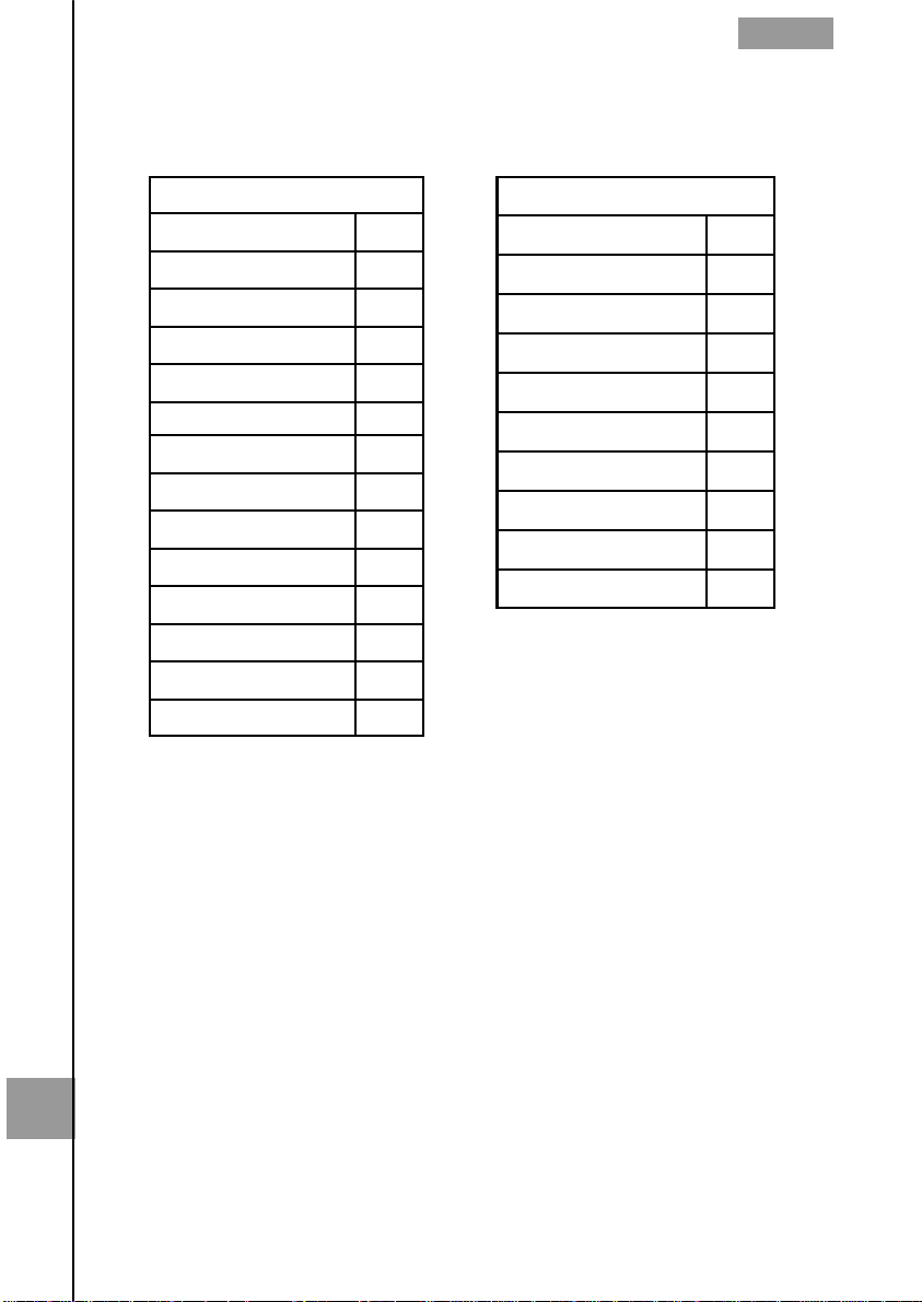
Annex B. Sound propagation velocity in some solids (in m/s).
ANNEX B
Pipe material
Aluminium 3080
Brass 2150
Bronze 2270
Cast iron 2550
Copper 2260
Ductile cast iron 2650
Glass 3300
Lead 2170
PE 1950
Plastic 2100
PP 2600
PVC 2395
Stainless steel 3175
Steel 3206
Bitumen 2500
Fiberglass 3430
Glass 3300
PE 1950
Plastic 2100
Porcelain 2540
PTFE 1400
PVC 2395
Rubber 1900
Titanium 3100
Lining material
B
46
Page 47
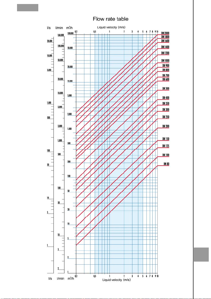
ANNEX C
47
C
Page 48

WARRANTY
Tecfluid S.A. guarantees all the products for a period of 24 months from their sale, against all faulty
materials, manufacturing or performance. This warranty does not cover failures which might be
imputed to misuse, use in an application different to that specified in the order, the result of service
or modification carried out by personnel not authorized by Tecfluid S.A., wrong handling or
accident.
This warranty is limited to cover the replacement or repair of the defective parts which have not
damaged due to misuse, being excluded all responsibility due to any other damage or the effects
of wear caused by the normal use of the devices.
Any consignment of devices for repair must observe a procedure which can be consulted in the
website www.tecfluid.com, “After-Sales” section.
All materials sent to our factory must be correctly packaged, clean and completely exempt of any
liquid, grease or toxic substances.
The devices sent for repair must enclose the corresponding form, which can be filled in via website
from the same “After-Sales” section.
Warranty for repaired or replaced components applies 6 months from repair or replacement date.
Anyway, the warranty period will last at least until the initial supply warranty period is over.
TRANSPORTATION
All consignments from the Buyer to the Seller´s installations for their credit, repair or replacement
must always be done at freight cost paid unless previous agreement.
The Seller will not accept any responsibility for possible damages caused on the devices during
transportation.
48
 Loading...