

Page 1
Programmable
instrumentation
for fluids
Totalizing Counter
CIP II
Instructions Manual
R-MI-CIP II Rev.: 0 English version
Page 2
1. INTRODUCTION
The pulse counter CIP II is designed to work with Tecfluid’s volumetric counters (Covol) and
turbines.
The circuit is based on a microprocessor that, in function of the pulses per unit of volume
programmed, totalizes the volume that flows through the meter and shows this value on the
display. The CIP II has two volume totalizers, one that can be reset (partial) and the other that
cannot be reset (total).
This instrument is battery powered and doesn’t require any wiring. This makes its installation
very easy.
2. OPERATION
To adapt the counter to the meter, the pulses per unit factor specified on the meter must be
programmed. To do this, the plastic front cover must be removed by unscrewing the four
screws on the corners. After that, the push buttons will be accessible.
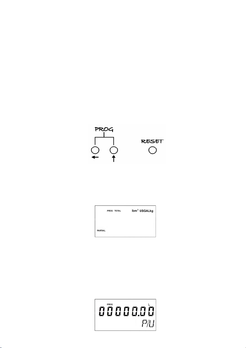
There are three push buttons with the following functions:
2.1 Programming
By pushing the two push buttons PROG at the same time for at least two seconds, the
display will change to the first stage of the programming mode.
2.1.1 Measuring Units
In this screen the measuring units should be programmed.
There are seven options of units: pounds (lb), cubic metres (m3), U.S. Gallons (USGAL),
litres (L), kilograms (kg), grams (g), and without specific units selected (all units off). The
selected unit will be flashing on the display (except when no specific units are selected).
Use the push button marked with the arrow pointing upwards to change from one unit to
the next. By pushing the two push buttons PROG at the same time (do not keep the push
buttons pushed) the selected unit will be saved in memory and the next programming
screen for the pulses per unit will appear. If the RESET push button is pressed then the
the next programming screen for the pulses per unit will appear but the selected unit will
not be saved in memory and the previous measuring unit will be retained.
2
Page 3
2.1.2 Pulses per Unit
In this mode there are 7 digits (five whole numbers and two decimals). The value that
must be introduced is the pulses per unit factor given on the label of the Covol or Turbine.
If the totalising unit selected is litres then introduce directly the value on the flowmeter
label. If you wish to totalise in m
3
then the pulses per litre of the flowmeter must be
multiplied by 1000. For example, if the turbine has a pulse per litre value of 21,02 then
21020,00 should be entered in the configuration. If the selected unit is U.S. Gallons then
the pulses/litre factor must be multiplied by 3.785. A turbine with 21.02 pulses/litre would
give a value of 79.56 pulses/USGAL. To totalise in any other unit, the pulses per litre
marked on the flowmeter must be multiplied by the conversion factor of litres/unit.
To introduce the required values, pushing the push button marked with the arrow pointing
upwards, the blinking digit will increase. Once the desired value of the digit is achieved, by
pressing the push button marked with the arrow pointing left, the blinking digit will be the
next digit to be modified. On the seventh digit, by pressing this push-button the blinking
digit will be the first digit on the display.
When the value of the pulses per unit is correct, by pushing the two push buttons PROG
at the same time for at least 2 seconds, this value will be automatically saved in the
memory and the instrument will return to normal working mode. Again, if the RESET push
button is pressed then the instrument will return to normal working mode without making any
changes in the pulses per unit factor.
NOTE: During the process of programming, the counter increases its power
consumption. In order to optimise the batter y life time, if during 30 seconds no push
buttons are pushed, the counter will return to the normal working mode. In this case
the data in the memory will not be changed.
Magnet
2.2 RESET
The partial totalizer can be reset in two ways:
By pushing the RESET push button during two seconds the counter will be set to zero.
It is possible to reset the counter without removing the plastic front cover by holding a
magnet horizontally just below the arrow pointing upwards during two seconds.
3
Page 4

2.3 COUNTER OVERFLOW
If one of the counters overflow, this condition is indicated at the right of the partial
totalizer. If neither of the counters has overflowed then this part of the display is blank.
When either of the counters overflows then the display will show “A/B”, where “A” is the
number of times that the partial counter has overflowed and “B” is the number of times the
total counter has overflowed. The digit that indicates the number of times the counter has
overflowed can be effectively placed in front of the digits of the counter to give an extra
digit. If a counter overflows more than 9 times then the digit will be shown as “X”.
If the partial counter overflows and the total counter has not, and then the partial counter
is reset, the display will then go blank again. The overflow indication of the partial counter
is reset when this counter is reset.
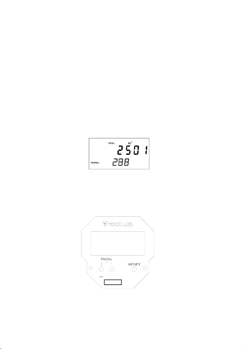
In the above screen the total counter is shown as having overflowed once (this would be
equivalent to a count of 10002501) and the partial counter as having overflowed eight
times (this would be equivalent to a count of 810288).
3. ELECTRICAL CONNECTION
No electrical connections are required for the local indication models. Just screw the
connector at the back of the counter onto the connector base of the flowmeter, previously
checking that the sealing gland is correctly situated in the bottom of the connector base.
The counters are supplied already configured for the type of flowmeter to be used
(COVOL or turbine).
For the remote wall mounting models, the connections should be made as follows:
The earth terminal of the CIP II connector should not be connected.
TM44 turbine flowmeter
Flowmeter terminal N. Connection CIP II terminal N.
1 Shield 1
2 Live Coil 2
3 Live Coil 3
COVOL Flowmeter
Flowmeter terminal N. Connection CIP II terminal N.
1 Reed 1
2 Reed 2
4. MAINTENANCE
The battery has a life time of about 5 years. To change the battery, the plastic front cover
must be removed. Then the battery, that is situated below the push buttons, can be
replaced.
After replacing the battery, it is not necessary to reprogram the pulses per litre factor of
the meter.
CR2450 batteries are easily found in the shops. If you prefer, we can change it in our
factory.
4
Page 5

5. MEASUREMENT ERROR CORRECTIONS
o
The calibration of the mechanical flow meters is made with water at 20
calibration for a liquid of density 1 kg/l and viscosity of 1 mPa·s. If the flow meter is used with
a liquid of other characteristics from the above specified or for reasons of turbulences in the
flow, measurement errors can be induced.
To correct these types of errors we can modify the pulses per litre factor programmed in the
instrument.
Example 1 - Shortage of volume
If we have a flow meter body which specifies i/l = 1.985, and when we check the volume of a
batch, we find that instead of having 100 litres as programmed, we only have 105 litres (5%
more) and we must apply the following correction:
i/l = Original Pulses per litre Factor = 1.985
V = Expected Volume = 100
Vr = Real Volume = 105
i/l n = New Pulses per litre Factor = ? (1.887)
6. CHANGE OF UNITS OF MEASUREMENT
In some cases we need to change the measurement units, for example, instead of working in
litres we need to work in kilograms. In this case we will need to know the density of the liquid
(ρ).
To change from litres to kg we must divide the pulse per litre factor by the density of the liquid
to obtain the new factor for programming the CIP II. For example, if the liquid has a density of
0.9 kg/litre, the meter gives us 200 pulses per litre and we must count in kg, we will program
the CIP II using 222.222 as the new pulses per litre factor to be able to count directly in kg.
Fk = Pulses per litre factor to count in kg
F = Original pulses per litre factor
ρ = Density of the liquid in kg/litre
F
k
C to obtain a
F
=
ρ
7. MODELS
CIP II __ __
L Local mounting on the flow meter (IP65)
M Remote wall mounting (IP65)
C COVOL input
T Turbine input
5
Page 6

8. TECHNICAL CHARACTERISTICS
8.1. Power supply
CR-2450 lithium battery
Nominal voltage: 3V
Capacity: 560 mAh
Power consumption: 8 µA
8.2. Totalizer Counter
N. of digits: 7
Size of the digit: 8 mm
Reset: Cannot be reset
8.3. Partial Counter
N. of digits: 5
Size of the digit: 6 mm
Reset: By means of push button or magnet.
8.4. General characteristics
Ingress protection: IP65
Ambient temperature range: 0 … +60 ºC
8.5. Input terminals for CIP II for local mounting
Terminal n.
1 Common Ground
2 Live Live
3 — Live
Input characteristics
8.5.1. COVOL
COVOL Turbine
This input is designed for a potential free contact between terminals 1 & 2 of the
connector. Terminal 1 is connected to the common of the instrument. This input
has a 1 M pull-up resistor connected to terminal 1 and to the 3,3 V power supply.
The input has a hysteresis with the switching points situated at about 1 V & 2,1 V.
If an open collector transistor is to be used as the switching element instead of a
COVOL, then the aforementioned parameters must be taken into account.
Due to the presence of a filter to avoid the effects of contact bounce, the maximum
pulse frequency for the COVOL input is 300 Hz.
The minimum input frequency is 0.06 Hz
+3.3V
1 M
2
1
6
Page 7
8.5.2 .Turbine
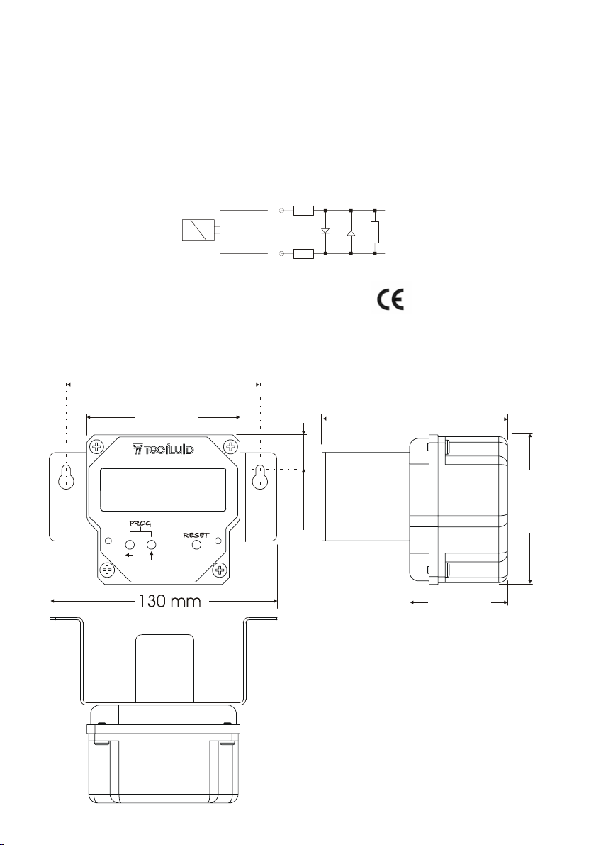
The turbine input is designed for connecting to the coil of a magnetic pick-up.
The input impedance is 1,2 K. This input is protected to limit the maximum
applied voltage to the circuit. This protection consists of two diodes in parallel and
two 100 Ohm resistors.
The maximum voltage that can be applied to the input is 10 Vpp. Voltages higher
that this can cause damage to the equipment.
The maximum input frequency is 5000 Hz
The minimum input voltage is 7 mVpp
100
2
Pick-up
Complies with the Directive EMC 89/336/EEC
9. DIMENSIONS FOR CIP II M
3
100
113 mm
1K
86 mm
20 mm
104 mm
84 mm
52 mm
7
Page 8
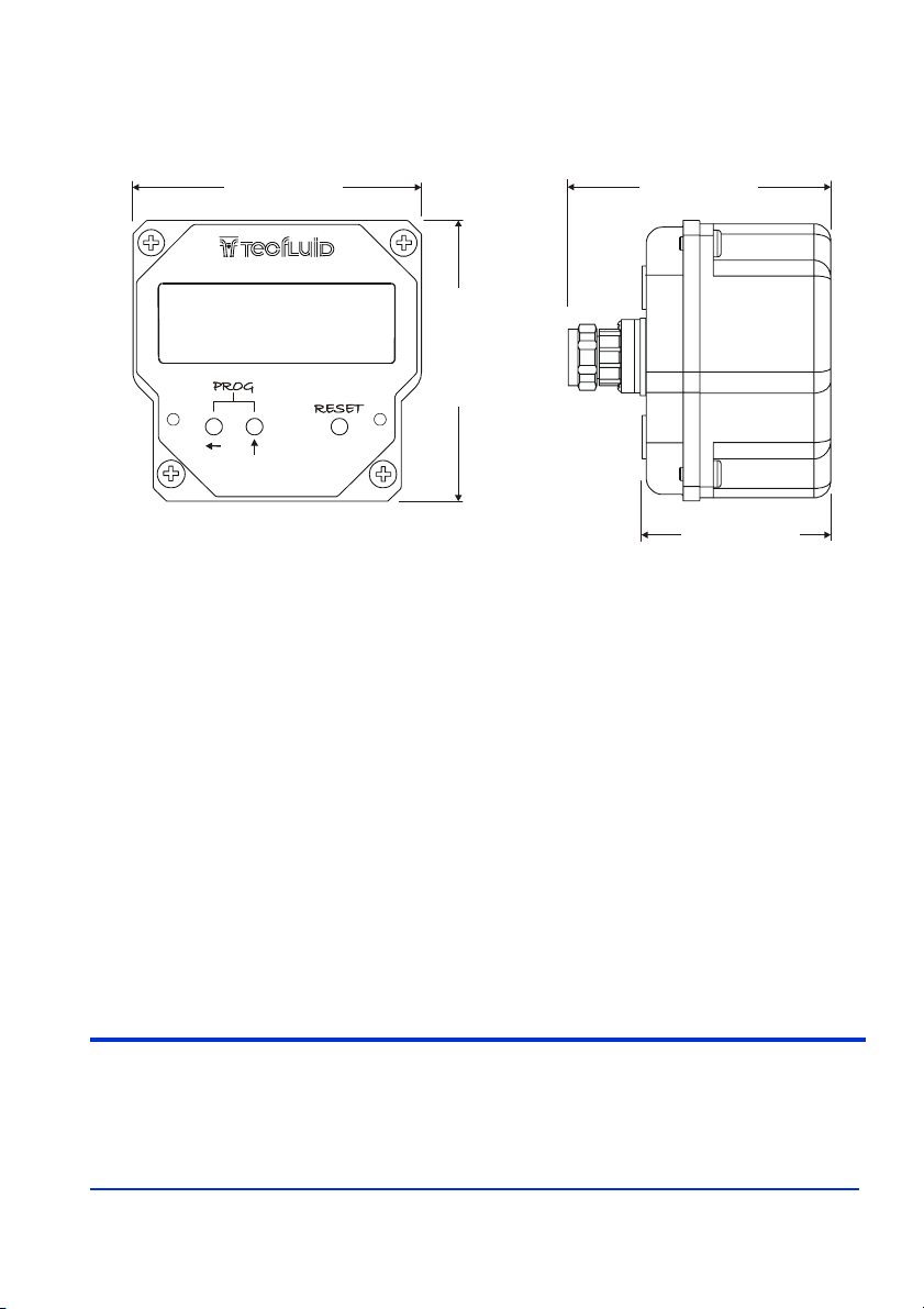
10. Dimensions for CIP II L
m
86 m
78 mm
84 mm
53 mm
WARRANTY
Tecfluid S.A. GUARANTEES ALL ITS PRODUCTS FOR A PERIOD OF 24 MONTHS, after
consignment, against all defects in materials and workmanship.
This warranty does not cover failures which can be imputed to misuse, use in an application different
to that specified in the order, the result of service or modification by un-authorized persons, bad
handling or accident.
This warranty is limited to cover the repair or replacement defective parts which have not been
damaged by misuse.
This warranty is limited to the repair of the equipment and all further and eventually following
damages are not covered by this warranty.
Any consignment of equipment to our factory or distributor must be previously authorised. The
consignment should be done with the equipment well packed, clean of any liquids, grease or
hazardous materials. Tecfluid S.A. will not accept any responsibility for damage done during
transport.
Together with the equipment, a note should be enclosed indicating the failure observed, the name,
address and telephone number of the sender.
TECFLUID, S.A.
Narcís Monturiol, 33
E-08960 Sant Just Desvern
Tel. + 34 933 724 511 - Fax + 34 934 734 449
E-mail: [email protected]
Internet: www.tecfluid.com
The technical data in this document is subject to modification without notification, if the technical innovations in the product or
manufacturing processes so require.
 Loading...